Downloads |
 Feedback Feedback
|
Table Of Contents
QoS: Tunnel Marking for L2TPv3 Tunnels
Prerequisites for QoS: Tunnel Marking for L2TPv3 Tunnels
Restrictions for QoS: Tunnel Marking for L2TPv3 Tunnels
Information About QoS: Tunnel Marking for L2TPv3 Tunnels
L2TPv3 Tunnel Marking Overview
Defining Class and Policy Maps for L2TPv3 Tunnel Marking Using the MQC
Configuring L2TPv3 Tunnel Marking
Benefits of L2TPv3 Tunnel Marking
How to Configure QoS: Tunnel Marking for L2TPv3 Tunnels
L2TPv3 Tunnel Marking and Traffic Policing
Attaching the Policy Map to an Interface or a VC
Configuration Examples for QoS: Tunnel Marking L2TPv3 Tunnels
Configuring Tunnel Marking on L2TPv3 Tunnels: Example
Verifying the Tunnel Marking on L2TPv3 Tunnels Configuration: Example
QoS: Tunnel Marking for L2TPv3 Tunnels
First Published: May 7, 2004Last Updated: February 28, 2006The QoS: Tunnel Marking for Layer 2 Tunnel Protocol Version 3 (L2TPv3) Tunnels feature introduces the capability to define and control the quality of service (QoS) for incoming customer traffic on the provider edge (PE) router in a service provider network.
History for the QoS: Tunnel Marking for L2TPv3 Tunnels Feature
12.0(28)S
This feature was introduced.
12.2(28)SB
This feature was integrated into Cisco IOS Release 12.2(28)SB.
Finding Support Information for Platforms and Cisco IOS Software Images
Use Cisco Feature Navigator to find information about platform support and Cisco IOS software image support. Access Cisco Feature Navigator at http://www.cisco.com/go/fn. You must have an account on Cisco.com. If you do not have an account or have forgotten your username or password, click Cancel at the login dialog box and follow the instructions that appear.
Contents
•
Prerequisites for QoS: Tunnel Marking for L2TPv3 Tunnels
•
•
•
•
Prerequisites for QoS: Tunnel Marking for L2TPv3 Tunnels
•
For information on CEF switching, consult the "Cisco Express Forwarding" section of the Cisco IOS Switching Services Configuration Guide.
•
Restrictions for QoS: Tunnel Marking for L2TPv3 Tunnels
•
•
•
1.
2.
3.
Note
Information About QoS: Tunnel Marking for L2TPv3 Tunnels
•
•
•
•
L2TPv3 Tunnel Marking Overview
The QoS: Tunnel Marking for L2TPv3 Tunnels feature allows you to define and control QoS for incoming customer traffic on the PE router in a service provider (SP) network. This feature lets you set (mark) either the IP precedence value or the differentiated services code point (DSCP) in the header of an L2TPv3 tunneled packet. L2TPv3 tunnel marking can be implemented by using a QoS marking command, such as set ip {dscp | precedence} [tunnel], and it can also be implemented in QoS traffic policing. This feature simplifies administrative overhead previously required to control customer bandwidth by allowing you to mark the L2TPv3 tunnel header on the incoming interface on the PE routers.
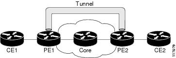
Figure 1 shows traffic being received from CE1 through PE1's incoming interface on which tunnel marking occurs. The traffic is encapsulated (tunneled) and the tunnel header is marked on PE1. The marked packets travel (tunnel) through the core and are decapsulated automatically on PE2's exit interface. This feature is designed to simplify classifying CE traffic and is configured only in the service provider network. This process is transparent to the customer sites. CE1 and CE2 simply exist as a single network.
Figure 1 Sample Tunnel Marking Topology
Defining Class and Policy Maps for L2TPv3 Tunnel Marking Using the MQC
To configure the tunnel marking for L2TPv3 tunnels, you must define a traffic class, configure a policy map, and then attach that policy map to the appropriate interface. These three tasks can be accomplished by using the MQC.
For information on the MQC, defining class and policy maps, consult the Modular Quality of Service Command-Line Interface section of the Cisco IOS Quality of Service Solutions Configuration Guide.
Configuring L2TPv3 Tunnel Marking
L2TPv3 tunnel marking is configured with the set ip precedence tunnel or set ip dscp tunnel command on PE routers that carry incoming traffic from customer sites. L2TPv3 tunnel marking allows you to mark the header of a L2TPv3 tunnel by setting a DSCP value from 0 to 63 or an IP precedence value from 0 to 7 to control L2TPv3 tunnel traffic bandwidth and priority.
L2TPv3 traffic can also be marked under traffic policing with the set-dscp-tunnel-transmit and the set-prec-tunnel-transmit commands. The tunnel marking value is from 0 to 63 for the set-dscp-tunnel-transmit command and from 0 to 7 for the set-prec-tunnel-transmit command. Under traffic policing, tunnel marking can be applied with "conform" and "exceed" action statements, allowing you to automatically apply a different value for traffic that does not conform to the expected traffic rate.
After the tunnel header is marked, L2TPv3 traffic is carried through the tunnel and across the service provider network. This traffic is decapsulated on the interface of the PE router that carries the outgoing traffic to the other customer site. The configuration of L2TPv3 tunnel marking is transparent to customer sites. All internal configuration is preserved.
It is important to distinguish between the set ip precedence and set ip dscp commands and the set ip precedence tunnel and set ip dscp tunnel commands.
•
•
Benefits of L2TPv3 Tunnel Marking
L2TPv3 Tunnel Marking Simplifies Customer Bandwidth Control at the Service Provider Site
L2TPv3 tunnel marking provides a simple mechanism to control the bandwidth of customer L2TPv3 traffic. This feature is configured entirely within the service provider network and only on interfaces that carry incoming traffic on the PE routers.
L2TPv3 Tunnel Marking Requires No Changes to Customer Configurations
The configuration of this feature is transparent to the customer sites and requires no configuration changes and has no impact on customer configurations.
L2TPv3 Definition
L2TPv3 is an Internet Engineering Task Force (IETF) Layer 2 Tunneling Protocol Extensions (l2tpext) working group draft that provides several enhancements to L2TP for the capability to tunnel any Layer 2 payload over L2TP. Specifically, L2TPv3 defines the L2TP protocol for tunneling Layer 2 payloads over an IP core network using Layer 2 virtual private networks (VPNs).
For information about L2TPv3, refer to the Layer 2 Tunnel Protocol Version 3 Cisco IOS Release 12.0(25)S feature module.
How to Configure QoS: Tunnel Marking for L2TPv3 Tunnels
The QoS: Tunnel Marking for L2TPv3 Tunnels feature introduces the capability for a service provider to define and control customer traffic bandwidth and priority on the interfaces of PE routers that carry incoming traffic. This section contains the following procedures.
•
•
•
•
Configuring a Class Map
To configure a class map, perform the following task.
SUMMARY STEPS
1.
2.
3.
4.
5.
DETAILED STEPS
Step 1
enable
Example:Router> enable
Enables privileged EXEC mode.
•
Step 2
configure terminal
Example:Router# configure terminal
Enters global configuration mode.
Step 3
class-map [match-all | match-any] class-map-name
Example:Router(config)# class-map MATCH_FRDE
Specifies the name of the class map to be created and enters class-map configuration mode.
The class map defines the criteria to use to differentiate the traffic. For example, you can use the class map to differentiate voice traffic from data traffic, based on a series of match criteria defined using the match command.
•
Note
Step 4
match l2tpv3-match-criteria
Example:Router(config-cmap)# match fr-de
Enables packet matching based on the specified class. You can enter one of three following match commands to define L2TPv3 match criteria tunnel marking:
•
•
•
Note
Step 5
exit
Example:Router(config-cmap)# exit
(Optional) Exits class-map configuration mode and enters global configuration mode.
Creating a Policy Map
To create a policy map and configure it to set either the precedence or the DSCP value in the header of a L2TPv3 tunneled packet, perform the following tasks.
L2TPv3 Tunnel Marking and Traffic Policing
Traffic policing allows you to control the maximum rate of traffic sent or received on an interface and to partition a network into multiple priority levels or class of service (CoS). If you use traffic policing in your network, you can also implement the L2TPv3 tunnel marking feature with the set-dscp-tunnel-transmit or set-prec-tunnel-transmit traffic policing commands in policy-map class configuration mode. Under traffic policing, tunnel marking can be applied with "conform" and "exceed" action statements, allowing you to apply a different value automatically for traffic that does not conform to the expected traffic rate.
L2TPv3 Tunnel Marking Values
The range of the tunnel marking values for the set ip dscp tunnel and set-dscp-tunnel-transmit commands is from 0 to 63; and the range of values for the set ip precedence tunnel and set-prec-tunnel-transmit commands is from 0 to 7.
Restrictions
It is possible to configure L2TPv3 tunnel marking and the ip tos command at the same time. However, MQC (L2TPv3) tunnel marking has higher priority over IP ToS commands, meaning that tunnel marking will always rewrite the IP header of the tunnel packet, overwriting the values set by ip tos commands. The order of enforcement is as follows when these commands are used simultaneously:
1.
2.
3.
Note
SUMMARY STEPS
1.
2.
3.
4.
5.
or
set ip precedence tunnel precedence-value
or
police bps [burst-normal] [burst-max] conform-action action exceed-action action [violate-action action]
6.
7.
DETAILED STEPS
Step 1
enable
Example:Router> enable
Enables privileged EXEC mode.
•
Step 2
configure terminal
Example:Router# configure terminal
Enters global configuration mode.
Step 3
policy-map policy-map-name
Example:Router(config)# policy-map TUNNEL_MARKING
Creates or modifies a policy map that can be attached to one or more interfaces to specify a service policy, and enters policy-map configuration mode.
•
Step 4
class {class-name | class-default}
Example:Router(config-pmap)# class MATCH_FRDE
Specifies the name of the class whose policy you want to create or change or specifies the default class (commonly known as the class-default class) before you configure its policy. Also enters policy-map class mode.
•
Step 5
set ip dscp tunnel dscp-value
Example:Router(config-pmap-c)# set ip dscp tunnel 3
Sets or marks the differentiated services code point (DSCP) value in the tunnel header of a Layer 2 Tunnel Protocol Version 3 (L2TPv3) tunneled packet on the ingress interface. The tunnel marking value is a number from 0 to 63 when configuring DSCP.
•
or
set ip precedence tunnel precedence-value
Example:Router(config-pmap-c)# set ip precedence tunnel 3
Sets or marks the IP precedence value in the tunnel header of a Layer 2 Tunnel Protocol Version 3 (L2TPv3) tunneled packet on the ingress interface. The tunnel marking value is a number from 0 to 7 when configuring IP precedence.
•
or
police bps [burst-normal] [burst-max] conform-action action exceed-action action [violate-action action]
Example:Router(config-pmap-c)# police 8000 conform-action set-dscp-tunnel-transmit 4
exceed-action set-dscp-tunnel-transmit 0
or
Router(config-pmap-c)# police 8000
conform-action set-prec-tunnel-transmit 4
exceed-action set-prec-tunnel-transmit 0
Configures traffic policing on the basis of the bits per second (bps) specified and the actions specified.
If you use traffic policing in your network, you can implement the L2TPv3 tunnel marking feature with the set-dscp-tunnel-transmit or set-prec-tunnel-transmit traffic policing commands instead of the set ip dscp tunnel or the set ip precedence tunnel commands shown in Step 5.
The tunnel marking value for the traffic policing commands is from 0 to 63 when using set-dscp-tunnel-transmit and from 0 to 7 when using set-prec-tunnel-transmit.
•
•
Note
Step 6
exit
Example:Router(config-pmap-c)# exit
(Optional) Exits policy-map class configuration mode and enters policy-map configuration mode.
Step 7
exit
Example:Router(config-pmap)# exit
(Optional) Exits policy-map configuration mode and enters global configuration mode.
Attaching the Policy Map to an Interface or a VC
To attach the policy map to an interface or a virtual circuit (VC), perform the following task.
Restrictions
Policy maps can be attached to main interfaces, subinterfaces, or ATM permanent virtual circuits (PVCs). Policy maps are attached to interfaces by using the service-policy command and specifying either the input or output keyword s to indicate the direction of the interface. This feature is supported only on ingress interfaces with the input keyword and should not be configured on egress interfaces with the output keyword.
SUMMARY STEPS
1.
2.
3.
4.
5.
6.
DETAILED STEPS
Verifying the Configuration
To verify that the feature is configured as intended and that either the IP precedence or DSCP value is set as expected, complete the following steps.
SUMMARY STEPS
1.
2.
and/or
3.
4.
DETAILED STEPS
Troubleshooting Tips
The commands in the "Verifying the Configuration" section allow you to verify that you achieved the intended configuration and that the feature is functioning correctly. If, after using the show commands listed above, you find that the configuration is not correct or the feature is not functioning as expected, perform these operations.
If the configuration is not the one you intended, complete the following procedures:
•
•
•
Configuration Examples for QoS: Tunnel Marking L2TPv3 Tunnels
This section provides the following configuration examples:
•
•
Configuring Tunnel Marking on L2TPv3 Tunnels: Example
The following is an example of a L2TPv3 tunnel marking configuration. In this sample, a class map called "MATCH_FRDE" has been configured to match traffic based on the Frame Relay DE bit.
Router> enableRouter# configure terminalRouter(config)# class-map MATCH_FRDERouter(config-cmap)# match fr-deRouter(config-cmap)# exitIn this part of the example configuration, a policy map called "TUNNEL_MARKING" has been created and the set ip dscp tunnel command has been configured in the policy map. You could use the set ip precedence tunnel command instead of the set ip dscp tunnel command if you do not use DSCP in your network.
Router(config)# policy-map TUNNEL_MARKING
Router(config-pmap)# class MATCH_FRDE
Router(config-pmap-c)# set ip dscp tunnel 3
Router(config-pmap-c)# end
Note
In this part of the example configuration, the policy map called "TUNNEL_MARKING" has been created and traffic policing has also been configured by using the police command and specifying the appropriate policing actions. The set-dscp-tunnel-transmit command can be used instead of the set-prec-tunnel-transmit if you use DSCP in your network.
Router(config)# policy-map TUNNEL_MARKING
Router(config-pmap)# class class-default
Router(config-pmap-c)# police 8000 conform-action set-prec-tunnel-transmit 4 exceed-action
set-prec-tunnel-transmit 0
Router(config-pmap-c)# endIn the final part of the example configuration, the policy map is attached to serial interface 0 in the inbound (input) direction by specifying the input keyword of the service-policy command.
Router(config)# interface serial 0Router(config-if)# service-policy input TUNNEL_MARKINGRouter(config-if)# endVerifying the Tunnel Marking on L2TPv3 Tunnels Configuration: Example
This section contains sample output from the show policy-map interface command and the show policy-map command. The output from these commands can be used to verify and monitor the feature configuration in your network.
The following is sample output from the show policy-map interface command. In this sample output, the character string "ip dscp tunnel 3" indicates that the tunnel marking on L2TPv3 feature has been configured to set the DSCP in the header of an L2TPv3 tunneled packet.
Router# show policy-map interfaceSeria0Service-policy input: tunnelClass-map: frde (match-all)0 packets, 0 bytes30 second offered rate 0 bps, drop rate 0 bpsMatch: fr-deQoS Setip dscp tunnel 3Packets marked 0Class-map: class-default (match-any)13736 packets, 1714682 bytes30 second offered rate 0 bps, drop rate 0 bpsMatch: any13736 packets, 1714682 bytes30 second rate 0 bpsThe following is sample output from the show policy-map command. In this sample output, the character string "ip precedence tunnel 4" indicates that the tunnel marking on L2TPv3 feature has been configured to set the IP precedence in the header of an L2TPv3 tunneled packet.
Router# show policy-mapPolicy Map TUNNEL_MARKINGClass MATCH_FRDEset ip precedence tunnel 4Additional References
The following sections provide references related to the QoS: Tunnel Marking for L2TPv3 Tunnels feature.
Related Documents
QoS commands: complete command syntax, command modes, command history, defaults, usage guidelines, and examples
Cisco IOS Quality of Service Solutions Command Reference, Release 12.3T
MQC
"Configuring the Modular Quality of Service Command-Line Interface" chapter in Cisco IOS Quality of Service Solutions Configuration Guide
L2TPv3
Layer 2 Tunnel Protocol Version 3 Cisco IOS Release 12.0(25)S feature module
DSCP
"Implementing DiffServ for End-to-End Quality of Service Overview" chapter in Cisco IOS Quality of Service Configuration Guide
Standards
MIBs
None
To locate and download MIBs for selected platforms, Cisco IOS releases, and feature sets, use Cisco MIB Locator found at the following URL:
RFCs
Technical Assistance
Command Reference
This section documents new and modified commands. All other commands used with this feature are documented in the Cisco IOS Release 12.3 command reference publications.
New Commands
Modified Commands
match atm clp
To specify the ATM cell loss priority (CLP) bit as a match criterion in a class map, use the match atm clp command in class-map configuration mode. To remove a previously specified ATM CLP bit as a match criterion, use the no form of this command.
match atm clp
no match atm clp
Syntax Description
This command has no keywords or arguments.
Defaults
No default behavior
Command Modes
Class-map configuration
Command History
12.0(28)S
This command was introduced.
12.2(28)SB
This command was integrated into Cisco IOS Release 12.2(28)SB.
Examples
In the following example, a class map called "MATCH_ATM_CLP" has been created to match traffic based on the ATM CLP bit:
Router(config)# class-map MATCH_ATM_CLPRouter(config-cmap)# match atm clpRouter(config-cmap)# endRelated Commands
match cos
To match a packet based on a Layer 2 class of service (CoS) marking, use the match cos command in class-map configuration mode. To remove a specific Layer 2 CoS/Inter-Switch Link (ISL) marking, use the no form of this command.
match cos cos-value [cos-value [cos-value [cos-value]]]
no match cos cos-value [cos-value [cos-value [cos-value]]]
Syntax Description
cos-value
Specific IEEE 802.1Q/ISL CoS value. The cos-value is from 0 to 7; up to four CoS values can be specified in one match cos statement.
Defaults
No match criteria are specified.
Command Modes
Class-map configuration
Command History
12.1(5)T
This command was introduced.
12.2(28)SB
This command was integrated into Cisco IOS Release 12.2(28)SB.
Examples
In the following example, the CoS-values of 1, 2, and 3 are successful match criteria for the interface that contains the classification policy called cos:
Router(config)# class-map cos
Router(config-cmap)# match cos 1 2 3
In the following example, classes called voice and video-n-data are created to classify traffic based on the CoS values. QoS treatment is then given to the appropriate packets (in this case, the QoS treatment is priority 64 and bandwidth 512) in the CoS-based-treatment policy map.
Router(config)# class-map voiceRouter(config-cmap)# match cos 7Router(config)# class-map video-n-dataRouter(config-cmap)# match cos 5Router(config)# policy-map cos-based-treatmentRouter(config-pmap)# class voiceRouter(config-pmap-c)# priority 64Router(config-pmap-c)# exitRouter(config-pmap)# class video-n-dataRouter(config-pmap-c)# bandwidth 512Router(config-pmap-c)# exitRouter(config-pmap)# exitRouter(config)# interface fastethernet0/0.1Router(config-if)# service-policy output cos-based-treatmentThe service policy configured in this section is attached to all packets leaving Fast Ethernet interface 0/0.1. The service policy can be attached to any interface that supports service policies.
Related Commands
match fr-de
To match packets with the Frame Relay discard eligibility (DE) bit set, use the match fr-de command in class-map configuration mode. To remove the match criteria, use the no form of this command.
match fr-de
no match fr-de
Syntax Description
This command has no arguments or keywords.
Command Default
Packets are not matched with the DE bit set.
Command Modes
Class-map configuration
Command History
Examples
The following example creates a class called match-fr-de and matches packets with the Frame Relay DE bit set.
Router(config)# class-map match-fr-deRouter(config-cmap)# match fr-deRouter(config)# exitRelated Commands
set fr-de
Changes the DE bit setting in the address field of a Frame Relay frame to 1 for all traffic leaving an interface.
set ip dscp tunnel
To set the differentiated services code point (DSCP) value in the tunnel header of a Layer 2 Tunnel Protocol Version 3 (L2TPv3) tunneled packet for tunnel marking, use the set ip dscp tunnel command in policy-map class configuration mode. To disable this functionality, use the no form of this command.
set ip dscp tunnel dscp-value
no set ip dscp tunnel dscp-value
Syntax Description
Defaults
The DSCP value is not set.
Command Modes
Policy-map class configuration
Command History
12.0(28)S
This command was introduced.
12.2(28)SB
This command was integrated into Cisco IOS Release 12.2(28)SB.
Usage Guidelines
It is possible to configure L2TPv3 tunnel marking and the ip tos command at the same time. However, Modular Quality of Service (QoS) Command-Line Interface (CLI) (MQC) (L2TPv3) tunnel marking has higher priority over IP ToS commands, meaning that tunnel marking always rewrites the IP header of the tunnel packet and overwrites the values set by ip tos commands. The order of enforcement is as follows when these commands are used simultaneously:
1.
2.
3.
This is designed behavior. We recommend that you configure only L2TPv3 tunnel marking and reconfigure any peers configured with the ip tos command to use L2TPv3 tunnel marking.
Examples
The following example shows the set ip dscp tunnel command used in a tunnel marking for L2TPv3 tunnels configuration. In this example, a class map called "class-cl" has been configured to match traffic based on the Frame Relay discard eligible (DE) bit. Also, policy map called "policy1" has been created within which the set ip dscp tunnel command has been configured.
Router> enableRouter# configure terminalRouter(config)# class-map class-c1Router(config-cmap)# match fr-deRouter(config-cmap)# exitRouter(config)# policy-map policy1
Router(config-pmap)# class tunnel
Router(config-pmap-c)# set ip dscp tunnel 5
Router(config-pmap-c)# end
Note
Related Commands
ip tos
Specifies the ToS level for IP traffic.
set ip precedence tunnel
Sets the precedence value in the header of an L2TPv3 tunneled packet.
set ip precedence tunnel
To set the precedence value in the header of a Layer 2 Tunnel Protocol Version 3 (L2TPv3) tunneled packet for tunnel marking, use the set ip precedence tunnel command in policy-map class configuration mode. To disable this functionality, use the no form of this command.
set ip precedence tunnel precedence-value
no set ip precedence tunnel precedence-value
Syntax Description
Defaults
The precedence value is not set.
Command Modes
Policy-map class configuration
Command History
12.0(28)S
This command was introduced.
12.2(28)SB
This command was integrated into Cisco IOS Release 12.2(28)SB.
Usage Guidelines
It is possible to configure L2TPv3 tunnel marking and the ip tos command at the same time. However, Modular Quality of Service (QoS) Command-Line Interface (CLI) (MQC) (L2TPv3) tunnel marking has higher priority over IP ToS commands, meaning that tunnel marking always rewrites the IP header of the tunnel packet and overwrites the values set by ip tos commands. The order of enforcement is as follows when these commands are used simultaneously:
1.
2.
3.
This is designed behavior. We recommend that you configure only L2TPv3 tunnel marking and reconfigure any peers configured with the ip tos command to use L2TPv3 tunnel marking.
Examples
The following example shows the set ip precedence tunnel command used in a tunnel marking for L2TPv3 tunnels configuration. In this example, a class map called "class-cl" has been configured to match traffic based on the Frame Relay discard eligible (DE) bit. Also, policy map called "policy1" has been created within which the set ip precedence tunnel command has been configured.
Router> enableRouter# configure terminalRouter(config)# class-map MATCH_FRDERouter(config-cmap)# match fr-deRouter(config-cmap)# exitRouter(config)# policy-map policy1
Router(config-pmap)# class tunnel
Router(config-pmap-c)# set ip precedence tunnel 7Router(config-pmap-c)# end
Note
Related Commands
ip tos
Specifies the ToS level for IP traffic in the TN3270 server.
set ip dscp tunnel
Sets the DSCP value in the header of an L2TPv3 tunneled packet.
police
To configure traffic policing, use the police command in policy-map class configuration mode or policy-map class police configuration mode. To remove traffic policing from the configuration, use the no form of this command.
police bps [burst-normal] [burst-max] conform-action action exceed-action action [violate-action action]
no police bps [burst-normal] [burst-max] conform-action action exceed-action action [violate-action action]
Syntax Description
Defaults
Disabled
Command Modes
Policy-map class configuration (when specifying a single action to be applied to a marked packet)
Policy-map class police configuration (when specifying multiple actions to be applied to a marked packet)
Command History
Usage Guidelines
Use the police command to mark a packet with different quality of service (QoS) values based on conformance to the service-level agreement.
Traffic policing will not be executed for traffic that passes through an interface.
Specifying Multiple Actions
The police command allows you to specify multiple policing actions. When specifying multiple policing actions when configuring the police command, note the following points:
•
•
Using the Police Command with the Traffic Policing Feature
The police command can be used with the Traffic Policing feature. The Traffic Policing feature works with a token bucket algorithm. Two types of token bucket algorithms are in Cisco IOS Release 12.1(5)T: a single-token bucket algorithm and a two-token bucket algorithm. A single-token bucket system is used when the violate-action option is not specified, and a two-token bucket system is used when the violate-action option is specified.
The token bucket algorithm for the police command that was introduced in Cisco IOS Release 12.0(5)XE is different from the token bucket algorithm for the police command introduced in Cisco IOS Release 12.1(5)T. For information on the token bucket algorithm introduced in Release 12.0(5)XE, refer to the Traffic Policing document for Release 12.0(5)XE. This document is available on the New Features for 12.0(5)XE feature documentation index (under Modular QoS CLI-related feature modules) at www.cisco.com.
The following are explanations of how the token bucket algorithms introduced in Cisco IOS Release 12.1(5)T work.
Token Bucket Algorithm with One Token Bucket
The one token bucket algorithm is used when the violate-action option is not specified in the police command command-line interface (CLI).
The conform bucket is initially set to the full size (the full size is the number of bytes specified as the normal burst size).
When a packet of a given size (for example, "B" bytes) arrives at specific time (time "T") the following actions occur:
•
(time between packets <which is equal to T - T1> * policer rate)/8 bytes
•
•
Token Bucket Algorithm with Two Token Buckets
The two-token bucket algorithm is used when the violate-action option is specified in the police command CLI.
The conform bucket is initially full (the full size is the number of bytes specified as the normal burst size).
The exceed bucket is initially full (the full exceed bucket size is the number of bytes specified in the maximum burst size).
The tokens for both the conform and exceed token buckets are updated based on the token arrival rate, or committed information rate (CIR).
When a packet of given size (for example, "B" bytes) arrives at specific time (time "T") the following actions occur:
•
The token arrival rate is calculated as follows:
(time between packets <which is equal to T-T1> * policer rate)/8 bytes
•
•
•
Examples
Token Bucket Algorithm with One Token Bucket Example
The token bucket algorithm for the police command that was introduced in Cisco IOS Release 12.0(5)XE is different from the token bucket algorithms introduced in Cisco IOS Release 12.1(5)T. The following example is for the token bucket algorithm with one token bucket introduced in Cisco IOS Release 12.1(5)T.
If the violate-action option is not specified when you configure a policy with the police command in Cisco IOS Release 12.1(5)T onward, the token bucket algorithm uses one token bucket. If the violate-action option is specified, the token bucket algorithm uses two token buckets. In the following example, the violate-action option is not specified, so the token bucket algorithm only uses one token bucket.
The following configuration shows users how to define a traffic class (using the class-map command) and associate the match criteria from the traffic class with the traffic policing configuration, which is configured in the service policy (using the policy-map command). The service-policy command is then used to attach this service policy to the interface.
In this particular example, traffic policing is configured with the average rate at 8000 bits per second and the normal burst size at 1000 bytes for all packets leaving Fast Ethernet interface 0/0:
Router(config)# class-map access-matchRouter(config-cmap)# match access-group 1Router(config-cmap)# exitRouter(config)# policy-map police-settingRouter(config-pmap)# class access-matchRouter(config-pmap-c)# police 8000 1000 conform-action transmit exceed-action dropRouter(config-pmap-c)# exitRouter(config-pmap)# exitRouter(config)# interface fastethernet 0/0Router(config-if)# service-policy output police-settingThe treatment of a series of packets leaving Fast Ethernet interface 0/0 depends on the size of the packet and the number of bytes remaining in the conform bucket. These packets are policed based on the following rules:
•
(time between packets <which is equal to T - T1> * policer rate)/8 bytes
•
•
In this example, the initial token buckets starts full at 1000 bytes. If a 450-byte packet arrives, the packet conforms because enough bytes are available in the conform token bucket. The conform action (send) is taken by the packet and 450 bytes are removed from the conform token bucket (leaving 550 bytes).
If the next packet arrives 0.25 seconds later, 250 bytes are added to the token bucket ((0.25 * 8000)/8), leaving 800 bytes in the token bucket. If the next packet is 900 bytes, the packet exceeds and the exceed action (drop) is taken. No bytes are taken from the token bucket.
Token Bucket Algorithm with Two Token Buckets Example
If the violate-action option is specified when you configure a policy with the police command in Cisco IOS Release 12.1(5)T onward, the token bucket algorithm uses two token buckets. The following example uses the token bucket algorithm with two token buckets.
The following configuration shows users how to define a traffic class (using the class-map command) and associate the match criteria from the traffic class with the traffic policing configuration, which is configured in the service policy (using the policy-map command). The service-policy command is then used to attach this service policy to the interface.
In this particular example, traffic policing is configured with the average rate at 8000 bits per second, the normal burst size at 1000 bytes, and the excess burst size at 1000 bytes for all packets leaving Fast Ethernet interface 0/0.
Router(config)# class-map access-matchRouter(config-cmap)# match access-group 1Router(config-cmap)# exitRouter(config)# policy-map police-settingRouter(config-pmap)# class access-matchRouter(config-pmap-c)# police 8000 1000 1000 conform-action transmit exceed-action set-qos-transmit 1 violate-action dropRouter(config-pmap-c)# exitRouter(config-pmap)# exitRouter(config)# interface fastethernet 0/0Router(config-if)# service-policy output police-settingThe treatment of a series of packets leaving Fast Ethernet interface 0/0 depends on the size of the packet and the number of bytes remaining in the conform and exceed token buckets. The series of packets are policed based on the following rules:
•
(time between packets <which is equal to T - T1> * policer rate)/8 bytes
•
•
•
In this example, the initial token buckets starts full at 1000 bytes. If a 450-byte packet arrives, the packet conforms because enough bytes are available in the conform token bucket. The conform action (send) is taken by the packet and 450 bytes are removed from the conform token bucket (leaving 550 bytes).
If the next packet arrives 0.25 seconds later, 250 bytes are added to the conform token bucket
((0.25 * 8000)/8), leaving 800 bytes in the conform token bucket. If the next packet is 900 bytes, the packet does not conform because only 800 bytes are available in the conform token bucket.The exceed token bucket, which starts full at 1000 bytes (as specified by the excess burst size) is then checked for available bytes. Because enough bytes are available in the exceed token bucket, the exceed action (set the QoS transmit value of 1) is taken and 900 bytes are taken from the exceed bucket (leaving 100 bytes in the exceed token bucket.
If the next packet arrives 0.40 seconds later, 400 bytes are added to the token buckets ((.40 * 8000)/8). Therefore, the conform token bucket now has 1000 bytes (the maximum number of tokens available in the conform bucket) and 200 bytes overflow the conform token bucket (because it only 200 bytes were needed to fill the conform token bucket to capacity). These overflow bytes are placed in the exceed token bucket, giving the exceed token bucket 300 bytes.
If the arriving packet is 1000 bytes, the packet conforms because enough bytes are available in the conform token bucket. The conform action (transmit) is taken by the packet, and 1000 bytes are removed from the conform token bucket (leaving 0 bytes).
If the next packet arrives 0.20 seconds later, 200 bytes are added to the token bucket ((.20 * 8000)/8). Therefore, the conform bucket now has 200 bytes. If the arriving packet is 400 bytes, the packet does not conform because only 200 bytes are available in the conform bucket. Similarly, the packet does not exceed because only 300 bytes are available in the exceed bucket. Therefore, the packet violates and the violate action (drop) is taken.
Conforming to the MPLS EXP Value Example
The following example shows that if packets conform to the rate limit, the MPLS EXP field is set to 5. If packets exceed the rate limit, the MPLS EXP field is set to 3.
Router(config)# policy-map input-IP-dscpRouter(config-pmap)# class dscp24Router(config-pmap-c)# police 8000 1500 1000Router(config-pmap-c)# conform-action set-mpls-experimental-imposition-transmit 5Router(config-pmap-c)# exceed-action set-mpls-experimental-imposition-transmit 3Router(config-pmap-c)# violate-action dropRelated Commands
police (two rates)
To configure traffic policing using two rates, the committed information rate (CIR) and the peak information rate (PIR), use the police command in policy-map configuration mode. To remove two-rate traffic policing from the configuration, use the no form of this command.
police cir cir [bc conform-burst] pir pir [be peak-burst] [conform-action action [exceed-action action [violate-action action]]]
no police cir cir [bc conform-burst] pir pir [be peak-burst] [conform-action action [exceed-action action [violate-action action]]]
Syntax Description
Defaults
Disabled
Command Modes
Policy-map configuration
Command History
Usage Guidelines
Two-rate traffic policing uses two token buckets—Tc and Tp—for policing traffic at two independent rates. Note the following points about the two token buckets:
•
•
Updating Token Buckets
The following scenario illustrates how the token buckets are updated:
A packet of B bytes arrives at time t. The last packet arrived at time t1. The CIR and the PIR token buckets at time t are represented by Tc(t) and Tp(t), respectively. Using these values and in this scenario, the token buckets are updated as follows:
Tc(t) = min(CIR * (t-t1) + Tc(t1), Bc)
Tp(t) = min(PIR * (t-t1) + Tp(t1), Be)
Marking Traffic
The two-rate policer marks packets as either conforming, exceeding, or violating a specified rate. The following points (using a packet of B bytes) illustrate how a packet is marked:
•
•
Otherwise, the packet is marked as conforming to the specified rate, and both token buckets—Tc(t) and Tp(t)—are updated as follows:
Tp(t) = Tp(t) - B
Tc(t) = Tc(t) - B
For example, if the CIR is 100 kbps, the PIR is 200 kbps, and a data stream with a rate of 250 kbps arrives at the two-rate policer, the packet would be marked as follows:
•
•
•
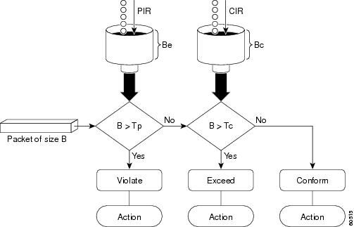
Marking Packets and Assigning Actions Flowchart
The flowchart in Figure 2 illustrates how the two-rate policer marks packets and assigns a corresponding action (that is, violate, exceed, or conform) to the packet.
Figure 2 Marking Packets and Assigning Actions with the Two-Rate Policer
Examples
In the following example, two-rate traffic policing is configured on a class to limit traffic to an average committed rate of 500 kbps and a peak rate of 1 Mbps:
Router(config)# class-map policeRouter(config-cmap)# match access-group 101Router(config-cmap)# policy-map policy1Router(config-pmap)# class policeRouter(config-pmap-c)# police cir 500000 bc 10000 pir 1000000 be 10000 conform-action transmit exceed-action set-prec-transmit 2 violate-action dropRouter(config-pmap-c)# exitRouter(config-pmap)# exitRouter(config)# interface serial3/0Router(config-if)# service-policy output policy1Router(config-if)# endRouter# show policy-map policy1Policy Map policy1Class policepolice cir 500000 conform-burst 10000 pir 1000000 peak-burst 10000 conform-action transmit exceed-action set-prec-transmit 2 violate-action dropTraffic marked as conforming to the average committed rate (500 kbps) will be sent as is. Traffic marked as exceeding 500 kbps, but not exceeding 1 Mbps, will be marked with IP Precedence 2 and then sent. All traffic marked as exceeding 1 Mbps will be dropped. The burst parameters are set to 10000 bytes.
In the following example, 1.25 Mbps of traffic is sent ("offered") to a policer class:
Router# show policy-map interface serial3/0Serial3/0Service-policy output: policy1Class-map: police (match all)148803 packets, 36605538 bytes30 second offered rate 1249000 bps, drop rate 249000 bpsMatch: access-group 101police:cir 500000 bps, conform-burst 10000, pir 1000000, peak-burst 100000conformed 59538 packets, 14646348 bytes; action: transmitexceeded 59538 packets, 14646348 bytes; action: set-prec-transmit 2violated 29731 packets, 7313826 bytes; action: dropconformed 499000 bps, exceed 500000 bps violate 249000 bpsClass-map: class-default (match-any)19 packets, 1990 bytes30 seconds offered rate 0 bps, drop rate 0 bpsMatch: anyThe two-rate policer marks 500 kbps of traffic as conforming, 500 kbps of traffic as exceeding, and 250 kbps of traffic as violating the specified rate. Packets marked as conforming to the rate will be sent as is, and packets marked as exceeding the rate will be marked with IP Precedence 2 and then sent. Packets marked as violating the rate are dropped.
Related Commands
show policy-map
To display the configuration of all classes for a specified service policy map or all classes for all existing policy maps, use the show policy-map command in EXEC mode.
show policy-map [policy-map]
Syntax Description
policy-map
(Optional) Name of the service policy map whose complete configuration is to be displayed.
Command Default
All existing policy map configurations are displayed.
Command Modes
EXEC
Command History
Usage Guidelines
The show policy-map command displays the configuration of a service policy map created using the policy-map command. You can use the show policy-map command to display all class configurations comprising any existing service policy map, whether or not that service policy map has been attached to an interface.
Examples
The following is sample output from the show policy-map command. This sample output displays the contents of a policy map called "policy1." In policy 1, traffic policing on the basis of a committed information rate (CIR) of 20 percent has been configured, and the bc and be have been specified in milliseconds. As part of the traffic policing configuration, optional conform, exceed, and violate actions have been specified.
Router# show policy-map policy1Policy Map policy1Class class1police cir percent 20 bc 300 ms pir percent 40 be 400 msconform-action transmitexceed-action dropviolate-action dropTable 1 describes the significant fields shown in the display.
Related Commands
show policy-map interface
To display the packet statistics of all classes that are configured for all service policies either on the specified interface or subinterface or on a specific permanent virtual circuit (PVC) on the interface, use the show policy-map interface command in privileged EXEC mode.
show policy-map interface [type access-control] interface-name [vc [vpi/] vci] [dlci dlci]
[input | output]ATM Shared Port Adapter
show policy-map interface atm slot/subslot/port[.subinterface]
Syntax Description
Defaults
The absence of both the forward slash (/) and a vpi value defaults the vpi value to 0. If this value is omitted, information for all virtual circuits (VCs) on the specified ATM interface or subinterface is displayed.
ATM Shared Port Adapter
When used with the ATM shared port adapter, this command has no default behavior or values.
Command Modes
Privileged EXEC
ATM Shared Port Adapter
When used with the ATM shared port adapter, EXEC or privileged EXEC.
Command History
Usage Guidelines
The show policy-map interface command displays the packet statistics for classes on the specified interface or the specified PVC only if a service policy has been attached to the interface or the PVC.
You can use the interface-name argument to display output for a PVC only for enhanced ATM port adapters (PA-A3) that support per-VC queueing.
The counters displayed after the show policy-map interface command is entered are updated only if congestion is present on the interface.
The show policy-map interface command displays policy information about Frame Relay PVCs only if Frame Relay Traffic Shaping (FRTS) is enabled on the interface.
The show policy-map interface command displays ECN marking information only if ECN is enabled on the interface.
To determine if shaping is active with HQF, check the queue depth field of the "(queue depth/total drops/no-buffer drops)" line in the show policy-map interface command output.
Examples
This section provides sample output from typical show policy-map interface commands. Depending upon the interface in use and the options enabled, the output you see may vary slightly from the ones shown below.
Example of Weighted Fair Queueing (WFQ) on Serial Interface
The following sample output of the show policy-map interface command displays the statistics for the serial 3/1 interface, to which a service policy called mypolicy (configured as shown below) is attached. Weighted fair queueing (WFQ) has been enabled on this interface. See Table 2 for an explanation of the significant fields that commonly appear in the command output.
policy-map mypolicyclass voicepriority 128class goldbandwidth 100class silverbandwidth 80random-detectRouter# show policy-map interface serial3/1 outputSerial3/1Service-policy output: mypolicyClass-map: voice (match-all)0 packets, 0 bytes5 minute offered rate 0 bps, drop rate 0 bpsMatch: ip precedence 5Weighted Fair QueueingStrict PriorityOutput Queue: Conversation 264Bandwidth 128 (kbps) Burst 3200 (Bytes)(pkts matched/bytes matched) 0/0(total drops/bytes drops) 0/0Class-map: gold (match-all)0 packets, 0 bytes5 minute offered rate 0 bps, drop rate 0 bpsMatch: ip precedence 2Weighted Fair QueueingOutput Queue: Conversation 265Bandwidth 100 (kbps) Max Threshold 64 (packets)(pkts matched/bytes matched) 0/0(depth/total drops/no-buffer drops) 0/0/0Class-map: silver (match-all)0 packets, 0 bytes5 minute offered rate 0 bps, drop rate 0 bpsMatch: ip precedence 1Weighted Fair QueueingOutput Queue: Conversation 266Bandwidth 80 (kbps)(pkts matched/bytes matched) 0/0(depth/total drops/no-buffer drops) 0/0/0exponential weight: 9mean queue depth: 0class Transmitted Random drop Tail drop Minimum Maximum Markpkts/bytes pkts/bytes pkts/bytes thresh thresh prob0 0/0 0/0 0/0 20 40 1/101 0/0 0/0 0/0 22 40 1/102 0/0 0/0 0/0 24 40 1/103 0/0 0/0 0/0 26 40 1/104 0/0 0/0 0/0 28 40 1/105 0/0 0/0 0/0 30 40 1/106 0/0 0/0 0/0 32 40 1/107 0/0 0/0 0/0 34 40 1/10rsvp 0/0 0/0 0/0 36 40 1/10Class-map: class-default (match-any)0 packets, 0 bytes5 minute offered rate 0 bps, drop rate 0 bpsMatch: anyExample of Traffic Shaping on Serial Interface
The following sample output from the show policy-map interface command displays the statistics for the serial 3/2 interface, to which a service policy called p1 (configured as shown below) is attached. Traffic shaping has been enabled on this interface. See Table 2 for an explanation of the significant fields that commonly appear in the command output.
policy-map p1class c1shape average 320000Router# show policy-map interface serial3/2 outputSerial3/2Service-policy output: p1Class-map: c1 (match-all)0 packets, 0 bytes5 minute offered rate 0 bps, drop rate 0 bpsMatch: ip precedence 0Traffic ShapingTarget Byte Sustain Excess Interval Increment AdaptRate Limit bits/int bits/int (ms) (bytes) Active320000 2000 8000 8000 25 1000 -Queue Packets Bytes Packets Bytes ShapingDepth Delayed Delayed Active0 0 0 0 0 noClass-map: class-default (match-any)0 packets, 0 bytes5 minute offered rate 0 bps, drop rate 0 bpsMatch: anyTable 2 describes significant fields commonly shown in the displays. The fields in the table are grouped according to the relevant QoS feature.
Table 2 show policy-map interface Field Descriptions 1
Service-policy output
Name of the output service policy applied to the specified interface or VC.
Class-map
Class of traffic being displayed. Output is displayed for each configured class in the policy. The choice for implementing class matches (for example, match-all or match-any) can also appear next to the traffic class.
packets and bytes
Number of packets (also shown in bytes) identified as belonging to the class of traffic being displayed.
offered rate
Rate, in kbps, of packets coming in to the class.
Note
drop rate
Rate, in kbps, at which packets are dropped from the class. The drop rate is calculated by subtracting the number of successfully transmitted packets from the offered rate.
Note
Match
Match criteria specified for the class of traffic. Choices include criteria such as IP precedence, IP differentiated services code point (DSCP) value, Multiprotocol Label Switching (MPLS) experimental (EXP) value, access groups, and QoS groups. For more information about the variety of match criteria options available, refer to the chapter "Configuring the Modular Quality of Service Command-Line Interface" in the Cisco IOS Quality of Service Solutions Configuration Guide.
Output Queue
The weighted fair queueing (WFQ) conversation to which this class of traffic is allocated.
Bandwidth
Bandwidth, in either kbps or percentage, configured for this class and the burst size.
pkts matched/bytes matched
Number of packets (also shown in bytes) matching this class that were placed in the queue. This number reflects the total number of matching packets queued at any time. Packets matching this class are queued only when congestion exists. If packets match the class but are never queued because the network was not congested, those packets are not included in this total. However, if process switching is in use, the number of packets is always incremented even if the network is not congested.
depth/total drops/no-buffer drops
Number of packets discarded for this class. No-buffer indicates that no memory buffer exists to service the packet.
exponential weight
Exponent used in the average queue size calculation for a WRED parameter group.
mean queue depth
Average queue depth based on the actual queue depth on the interface and the exponential weighting constant. It is a fluctuating average. The minimum and maximum thresholds are compared against this value to determine drop decisions.
class
IP precedence level.
Transmitted pkts/bytes
Number of packets (also shown in bytes) passed through WRED and not dropped by WRED.
Note
Random drop pkts/bytes
Number of packets (also shown in bytes) randomly dropped when the mean queue depth is between the minimum threshold value and the maximum threshold value for the specified IP precedence level.
Tail drop pkts/bytes
Number of packets dropped when the mean queue depth is greater than the maximum threshold value for the specified IP precedence level.
Minimum thresh
Minimum threshold. Minimum WRED threshold in number of packets.
Maximum thresh
Maximum threshold. Maximum WRED threshold in number of packets.
Mark prob
Mark probability. Fraction of packets dropped when the average queue depth is at the maximum threshold.
Target Rate
Rate used for shaping traffic.
Byte Limit
Maximum number of bytes that can be transmitted per interval. Calculated as follows:
((Bc+Be) /8) x 1
Sustain bits/int
Committed burst (Bc) rate.
Excess bits/int
Excess burst (Be) rate.
Interval (ms)
Time interval value in milliseconds (ms).
Increment (bytes)
Number of credits (in bytes) received in the token bucket of the traffic shaper during each time interval.
Queue Depth
Current queue depth of the traffic shaper.
Packets
Total number of packets that have entered the traffic shaper system.
Bytes
Total number of bytes that have entered the traffic shaper system.
Packets Delayed
Total number of packets delayed in the queue of the traffic shaper before being transmitted.
Bytes Delayed
Total number of bytes delayed in the queue of the traffic shaper before being transmitted.
Shaping Active
Indicates whether the traffic shaper is active. For example, if a traffic shaper is active, and the traffic being sent exceeds the traffic shaping rate, a "yes" appears in this field.
1 A number in parentheses may appear next to the service-policy output name, class-map name, and match criteria information. The number is for Cisco internal use only and can be disregarded.
Example of Precedence-Based Aggregate WRED on ATM Shared Port Adapter
The following sample output of the show policy-map interface command displays the statistics for the ATM shared port adapter interface 4/1/0.10, to which a service policy called prec-aggr-wred (configured as shown below) is attached. Because aggregate WRED has been enabled on this interface, the class through Mark Prob statistics are aggregated by subclasses. See Table 3 for an explanation of the significant fields that commonly appear in the command output.
Router(config)# policy-map prec-aggr-wredRouter(config-pmap)# class class-defaultRouter(config-pmap-c)# random-detect aggregateRouter(config-pmap-c)# random-detect precedence values 0 1 2 3 minimum thresh 10 maximum-thresh 100 mark-prob 10Router(config-pmap-c)# random-detect precedence values 4 5 minimum-thresh 40 maximum-thresh 400 mark-prob 10Router(config-pmap-c)# random-detect precedence values 6 minimum-thresh 60 maximum-thresh 600 mark-prob 10Router(config-pmap-c)# random-detect precedence values 7 minimum-thresh 70 maximum-thresh 700 mark-prob 10Router(config-pmap-c)# interface ATM4/1/0.10 point-to-pointRouter(config-subif)# ip address 10.0.0.2 255.255.255.0Router(config-subif)# pvc 10/110Router(config-subif)# service-policy output prec-aggr-wred
Router# show policy-map interface a4/1/0.10ATM4/1/0.10: VC 10/110 -Service-policy output: prec-aggr-wredClass-map: class-default (match-any)0 packets, 0 bytes5 minute offered rate 0 bps, drop rate 0 bpsMatch: anyExp-weight-constant: 9 (1/512)Mean queue depth: 0class Transmitted Random drop Tail drop Minimum Maximum Markpkts/bytes pkts/bytes pkts/bytes thresh thresh prob0 1 2 3 0/0 0/0 0/0 10 100 1/104 5 0/0 0/0 0/0 40 400 1/106 0/0 0/0 0/0 60 600 1/107 0/0 0/0 0/0 70 700 1/10Example of DSCP-Based Aggregate WRED on ATM Shared Port Adapter
The following sample output of the show policy-map interface command displays the statistics for the ATM shared port adapter interface 4/1/0.11, to which a service policy called dscp-aggr-wred (configured as shown below) is attached. Because aggregate WRED has been enabled on this interface, the class through Mark Prob statistics are aggregated by subclasses. See Table 3 for an explanation of the significant fields that commonly appear in the command output.
Router(config)# policy-map dscp-aggr-wredRouter(config-pmap)# class class-defaultRouter(config-pmap-c)# random-detect dscp-based aggregate minimum-thresh 1 maximum-thresh 10 mark-prob 10Router(config-pmap-c)# random-detect dscp values 0 1 2 3 4 5 6 7 minimum-thresh 10 maximum-thresh 20 mark-prob 10Router(config-pmap-c)# random-detect dscp values 8 9 10 11 minimum-thresh 10 maximum-thresh 40 mark-prob 10Router(config)# interface ATM4/1/0.11 point-to-pointRouter(config-subif)# ip address 10.0.0.2 255.255.255.0Router(config-subif)# pvc 11/101Router(config-subif)# service-policy output dscp-aggr-wred
Router# show policy-map interface a4/1/0.11ATM4/1/0.11: VC 11/101 -Service-policy output: dscp-aggr-wredClass-map: class-default (match-any)0 packets, 0 bytes5 minute offered rate 0 bps, drop rate 0 bpsMatch: anyExp-weight-constant: 0 (1/1)Mean queue depth: 0class Transmitted Random drop Tail drop Minimum Maximum Markpkts/bytes pkts/bytes pkts/bytes thresh thresh probdefault 0/0 0/0 0/0 1 10 1/100 1 2 34 5 6 7 0/0 0/0 0/0 10 20 1/108 9 10 11 0/0 0/0 0/0 10 40 1/10Table 3 describes the significant fields shown in the display when aggregate WRED is configured for an ATM shared port adapter.
Frame Relay Voice-Adaptive Traffic-Shaping show policy interface Command Example
The following sample output shows that Frame Relay voice-adaptive traffic shaping is currently active and has 29 seconds left on the deactivation timer. With traffic shaping active and the deactivation time set, this means that the current sending rate on DLCI 201 is minCIR, but if no voice packets are detected for 29 seconds, the sending rate will increase to CIR.
Router# show policy interface Serial3/1.1Serial3/1.1:DLCI 201 -Service-policy output:MQC-SHAPE-LLQ1Class-map:class-default (match-any)1434 packets, 148751 bytes30 second offered rate 14000 bps, drop rate 0 bpsMatch:anyTraffic ShapingTarget/Average Byte Sustain Excess Interval IncrementRate Limit bits/int bits/int (ms) (bytes)63000/63000 1890 7560 7560 120 945Adapt Queue Packets Bytes Packets Bytes ShapingActive Depth Delayed Delayed ActiveBECN 0 1434 162991 26 2704 yesVoice Adaptive Shaping active, time left 29 secsTable 4 describes the significant fields shown in the display. Significant fields that are not described in Table 4 are described in Table 2, "show policy-map interface Field Descriptions."
Two-Rate Traffic Policing show policy-map interface Command Example
The following is sample output from the show policy-map interface command when two-rate traffic policing has been configured. In the example below, 1.25 Mbps of traffic is sent ("offered") to a policer class.
Router# show policy-map interface serial3/0Serial3/0Service-policy output: policy1Class-map: police (match all)148803 packets, 36605538 bytes30 second offered rate 1249000 bps, drop rate 249000 bpsMatch: access-group 101police:cir 500000 bps, conform-burst 10000, pir 1000000, peak-burst 100000conformed 59538 packets, 14646348 bytes; action: transmitexceeded 59538 packets, 14646348 bytes; action: set-prec-transmit 2violated 29731 packets, 7313826 bytes; action: dropconformed 499000 bps, exceed 500000 bps violate 249000 bpsClass-map: class-default (match-any)19 packets, 1990 bytes30 seconds offered rate 0 bps, drop rate 0 bpsMatch: anyThe two-rate traffic policer marks 500 kbps of traffic as conforming, 500 kbps of traffic as exceeding, and 250 kbps of traffic as violating the specified rate. Packets marked as conforming will be sent as is, and packets marked as exceeding will be marked with IP Precedence 2 and then sent. Packets marked as violating the specified rate are dropped.
Table 5 describes the significant fields shown in the display.
Multiple Traffic Policing Actions show policy-map interface Command Example
The following is sample output from the show policy-map command when the Policer Enhancement — Multiple Actions feature has been configured. The sample output from the show policy-map interface command displays the statistics for the serial 3/2 interface, to which a service policy called "police" (configured as shown below) is attached.
policy-map policeclass class-defaultpolice cir 1000000 pir 2000000conform-action transmitexceed-action set-prec-transmit 4exceed-action set-frde-transmitviolate-action set-prec-transmit 2violate-action set-frde-transmitRouter# show policy-map interface serial3/2Serial3/2: DLCI 100 -Service-policy output: policeClass-map: class-default (match-any)172984 packets, 42553700 bytes5 minute offered rate 960000 bps, drop rate 277000 bpsMatch: anypolice:cir 1000000 bps, bc 31250 bytes, pir 2000000 bps, be 31250 bytesconformed 59679 packets, 14680670 bytes; actions:transmitexceeded 59549 packets, 14649054 bytes; actions:set-prec-transmit 4set-frde-transmitviolated 53758 packets, 13224468 bytes; actions:set-prec-transmit 2set-frde-transmitconformed 340000 bps, exceed 341000 bps, violate 314000 bpsThe sample output from show policy-map interface command shows the following:
•
•
•
Note
Table 6 describes the significant fields shown in the display.
Explicit Congestion Notification show policy-map interface Command Example
The following is sample output from the show policy-map interface command when the WRED — Explicit Congestion Notification (ECN) feature has been configured. The words "explicit congestion notification" included in the output indicate that ECN has been enabled.
Router# show policy-map interface Serial4/1Serial4/1Service-policy output:policy_ecnClass-map:prec1 (match-all)1000 packets, 125000 bytes30 second offered rate 14000 bps, drop rate 5000 bpsMatch:ip precedence 1Weighted Fair QueueingOutput Queue:Conversation 42Bandwidth 20 (%)Bandwidth 100 (kbps)(pkts matched/bytes matched) 989/123625(depth/total drops/no-buffer drops) 0/455/0exponential weight:9explicit congestion notificationmean queue depth:0class Transmitted Random drop Tail drop Minimum Maximum Markpkts/bytes pkts/bytes pkts/bytes threshold threshold probability0 0/0 0/0 0/0 20 40 1/101 545/68125 0/0 0/0 22 40 1/102 0/0 0/0 0/0 24 40 1/103 0/0 0/0 0/0 26 40 1/104 0/0 0/0 0/0 28 40 1/105 0/0 0/0 0/0 30 40 1/106 0/0 0/0 0/0 32 40 1/107 0/0 0/0 0/0 34 40 1/10rsvp 0/0 0/0 0/0 36 40 1/10class ECN Markpkts/bytes0 0/01 43/53752 0/03 0/04 0/05 0/06 0/07 0/0rsvp 0/0Table 7 describes the significant fields shown in the display.
Class-Based RTP and TCP Header Compression show policy-map interface Command Example
The following sample output from the show policy-map interface command shows the RTP header compression has been configured for a class called "prec2" in the policy map called "p1".
The show policy-map interface command output displays the type of header compression configured (RTP), the interface to which the policy map called "p1" is attached (Serial 4/1), the total number of packets, the number of packets compressed, the number of packets saved, the number of packets sent, and the rate at which the packets were compressed (in bits per second (bps)).
In this example, User Datagram Protocol (UDP)/RTP header compressions have been configured, and the compression statistics are included at the end of the display.
Router# show policy-map interface Serial4/1Serial4/1Service-policy output:p1Class-map:class-default (match-any)1005 packets, 64320 bytes30 second offered rate 16000 bps, drop rate 0 bpsMatch:anycompress:header ip rtpUDP/RTP Compression:Sent:1000 total, 999 compressed,41957 bytes saved, 17983 bytes sent3.33 efficiency improvement factor99% hit ratio, five minute miss rate 0 misses/sec, 0 maxrate 5000 bpsTable 8 describes the significant fields shown in the display.
Table 8 show policy-map interface Field Descriptions—Configured for Class-Based RTP and TCP Header Compression1
Service-policy output
Name of the output service policy applied to the specified interface or VC.
Class-map
Class of traffic being displayed. Output is displayed for each configured class in the policy. The choice for implementing class matches (for example, match-all or match-any) can also appear next to the traffic class.
packets, bytes
Number of packets (also shown in bytes) identified as belonging to the class of traffic being displayed.
offered rate
Rate, in kbps, of packets coming in to the class.
Note
UDP/RTP Compression
Indicates that RTP header compression has been configured for the class.
Sent total
Count of every packet sent, both compressed packets and full-header packets.
Sent compressed
Count of number of compressed packets sent.
bytes saved
Total number of bytes saved (that is, bytes not needing to be sent).
bytes sent
Total number of bytes sent for both compressed and full-header packets.
efficiency improvement factor
The percentage of increased bandwidth efficiency as a result of header compression. For example, with RTP streams, the efficiency improvement factor can be as much as 2.9 (or 290 percent).
hit ratio
Used mainly for troubleshooting purposes, this is the percentage of packets found in the context database. In most instances, this percentage should be high.
five minute miss rate
The number of new traffic flows found in the last five minutes.
misses/sec
maxThe average number of new traffic flows found per second, and the highest rate of new traffic flows to date.
rate
The actual traffic rate (in bits per second) after the packets are compressed.
1 A number in parentheses may appear next to the service-policy output name and the class-map name. The number is for Cisco internal use only and can be disregarded.
Modular QoS CLI (MQC) Unconditional Packet Discard show policy-map interface Command Example
The following sample output from the show policy-map interface command displays the statistics for the Serial2/0 interface, to which a policy map called "policy1" is attached. The discarding action has been specified for all the packets belonging to a class called "c1." In this example, 32000 bps of traffic is sent ("offered") to the class and all of them are dropped. Therefore, the drop rate shows 32000 bps.
Router# show policy-map interface Serial2/0Serial2/0Service-policy output: policy1Class-map: c1 (match-all)10184 packets, 1056436 bytes5 minute offered rate 32000 bps, drop rate 32000 bpsMatch: ip precedence 0dropTable 9 describes the significant fields shown in the display.
Table 9 show policy-map interface Field Descriptions—Configured for MQC Unconditional Packet Discard1
Service-policy output
Name of the output service policy applied to the specified interface or VC.
Class-map
Class of traffic being displayed. Output is displayed for each configured class in the policy. The choice for implementing class matches (for example, match-all or match-any) can also appear next to the traffic class.
packets, bytes
Number of packets (also shown in bytes) identified as belonging to the class of traffic being displayed.
offered rate
Rate, in kbps, of packets coming in to the class.
Note
drop rate
Rate, in kbps, at which packets are dropped from the class. The drop rate is calculated by subtracting the number of successfully transmitted packets from the offered rate.
Note
Match
Match criteria specified for the class of traffic. Choices include criteria such as the Layer 3 packet length, IP precedence, IP DSCP value, MPLS experimental value, access groups, and QoS groups. For more information about the variety of match criteria options available, refer to the chapter "Configuring the Modular Quality of Service Command-Line Interface" in the Cisco IOS Quality of Service Solutions Configuration Guide.
drop
Indicates that the packet discarding action for all the packets belonging to the specified class has been configured.
1 A number in parentheses may appear next to the service-policy output name and the class-map name. The number is for Cisco internal use only and can be disregarded.
Percentage-Based Policing and Shaping show policy-map interface Command Example
The following sample output from the show policy-map interface command shows traffic policing configured using a CIR based on a bandwidth of 20 percent. The CIR and committed burst (Bc) in milliseconds (ms) are included in the display.
Router# show policy-map interface Serial3/1Serial3/1Service-policy output: mypolicyClass-map: gold (match-any)0 packets, 0 bytes5 minute offered rate 0 bps, drop rate 0 bpsMatch: anypolice:cir 20 % bc 10 mscir 2000000 bps, bc 2500 bytespir 40 % be 20 mspir 4000000 bps, be 10000 bytesconformed 0 packets, 0 bytes; actions: transmit exceeded 0 packets, 0 bytes; actions: dropviolated 0 packets, 0 bytes; actions:dropconformed 0 bps, exceed 0 bps, violate 0 bpsTable 10 describes the significant fields shown in the display.
Table 10 show policy-map interface Field Descriptions—Configured for Percentage-Based Policing and Shaping1
Service-policy output
Name of the output service policy applied to the specified interface or VC.
Class-map
Class of traffic being displayed. Output is displayed for each configured class in the policy. The choice for implementing class matches (for example, match-all or match-any) can also appear next to the traffic class.
packets, bytes
Number of packets (also shown in bytes) identified as belonging to the class of traffic being displayed.
offered rate
Rate, in kbps, of packets coming in to the class.
Note
police
Indicates that traffic policing based on a percentage of bandwidth has been enabled. Also, displays the bandwidth percentage, the CIR, and the committed burst (Bc) size in ms.
conformed, actions
Displays the number of packets and bytes marked as conforming to the specified rates, and the action to be taken on those packets.
exceeded, actions
Displays the number of packets and bytes marked as exceeding the specified rates, and the action to be taken on those packets.
1 A number in parentheses may appear next to the service-policy output name and the class-map name. The number is for Cisco internal use only and can be disregarded.
Traffic Shaping show policy-map interface Command Example
The following sample output from the show policy-map interface command (shown below) displays the statistics for the serial 3/2 interface. Traffic shaping has been enabled on this interface, and an average rate of 20 percent of the bandwidth has been specified.
Router# show policy-map interface Serial3/2Serial3/2Service-policy output: p1Class-map: c1 (match-all)0 packets, 0 bytes5 minute offered rate 0 bps, drop rate 0 bpsMatch: anyTraffic ShapingTarget/Average Byte Sustain Excess Interval Increment AdaptRate Limit bits/int bits/int (ms) (bytes) Active 20 % 10 (ms) 20 (ms)201500/201500 1952 7808 7808 38 976 -Queue Packets Bytes Packets Bytes ShapingDepth Delayed Delayed Active0 0 0 0 0 noTable 11 describes the significant fields shown in the display.
Table 11 show policy-map interface Field Descriptions—Configured for Percentage-Based Policing and Shaping (with Traffic Shaping Enabled)1
Service-policy output
Name of the output service policy applied to the specified interface or VC.
Class-map
Class of traffic being displayed. Output is displayed for each configured class in the policy. The choice for implementing class matches (for example, match-all or match-any) can also appear next to the traffic class.
packets, bytes
Number of packets (also shown in bytes) identified as belonging to the class of traffic being displayed.
offered rate
Rate, in kbps, of packets coming in to the class.
Note
drop rate
Rate, in kbps, at which packets are dropped from the class. The drop rate is calculated by subtracting the number of successfully transmitted packets from the offered rate.
Match
Match criteria specified for the class of traffic. Choices include criteria such as the Layer 3 packet length, IP precedence, IP DSCP value, MPLS experimental value, access groups, and quality of service (QoS) groups. For more information about the variety of match criteria options that are available, refer to the chapter "Configuring the Modular Quality of Service Command-Line Interface" in the Cisco IOS Quality of Service Solutions Configuration Guide, Release 12.2.
Traffic Shaping
Indicates that traffic shaping based on a percentage of bandwidth has been enabled.
Target /Average Rate
Rate (percentage) used for shaping traffic and the number of packets meeting that rate.
Byte Limit
Maximum number of bytes that can be transmitted per interval. Calculated as follows:
((Bc+Be) /8 ) x 1
Sustain bits/int
Committed burst (Bc) rate.
Excess bits/int
Excess burst (Be) rate.
Interval (ms)
Time interval value in milliseconds (ms).
Increment (bytes)
Number of credits (in bytes) received in the token bucket of the traffic shaper during each time interval.
Adapt Active
Indicates whether adaptive shaping is enabled.
Queue Depth
Current queue depth of the traffic shaper.
Packets
Total number of packets that have entered the traffic shaper system.
Bytes
Total number of bytes that have entered the traffic shaper system.
Packets Delayed
Total number of packets delayed in the queue of the traffic shaper before being transmitted.
Bytes Delayed
Total number of bytes delayed in the queue of the traffic shaper before being transmitted.
Shaping Active
Indicates whether the traffic shaper is active. For example, if a traffic shaper is active, and the traffic being sent exceeds the traffic shaping rate, a "yes" appears in this field.
1 A number in parentheses may appear next to the service-policy output name, class-map name, and match criteria information. The number is for Cisco internal use only and can be disregarded.
Packet Classification Based on Layer 3 Packet Length show policy-map interface Command Example
The following sample output from the show policy-map interface command displays the packet statistics for the Ethernet4/1 interface, to which a service policy called "mypolicy" is attached. The Layer 3 packet length has been specified as a match criterion for the traffic in the class called "class1".
Router# show policy-map interface Ethernet4/1Ethernet4/1Service-policy input: mypolicyClass-map: class1 (match-all)500 packets, 125000 bytes5 minute offered rate 4000 bps, drop rate 0 bpsMatch: packet length min 100 max 300QoS Setqos-group 20Packets marked 500Table 12 describes the significant fields shown in the display.
Table 12 show policy-map interface Field Descriptions—Configured for Packet Classification Based on Layer 3 Packet Length1
Service-policy input
Name of the input service policy applied to the specified interface or VC.
Class-map
Class of traffic being displayed. Output is displayed for each configured class in the policy. The choice for implementing class matches (for example, match-all or match-any) can also appear next to the traffic class.
packets, bytes
Number of packets (also shown in bytes) identified as belonging to the class of traffic being displayed.
offered rate
Rate, in kbps, of packets coming in to the class.
Note
drop rate
Rate, in kbps, at which packets are dropped from the class. The drop rate is calculated by subtracting the number of successfully transmitted packets from the offered rate.
Match
Match criteria specified for the class of traffic. Choices include criteria such as the Layer 3 packet length, IP precedence, IP DSCP value, MPLS experimental value, access groups, and QoS groups.
QoS Set, qos-group, Packets marked
Indicates that class-based packet marking based on the QoS group has been configured. Includes the qos-group number and the number of packets marked.
1 A number in parentheses may appear next to the service-policy input name, class-map name, and match criteria information. The number is for Cisco internal use only and can be disregarded.
Enhanced Packet Marking show policy-map interface Command Example
The following sample output of the show policy-map interface command shows the service policies attached to a FastEthernet subinterface. In this example, a service policy called "policy1" has been attached. In "policy1", a table map called "table-map1" has been configured. The values in "table-map1" will be used to map the precedence values to the corresponding class of service (CoS) values.
Router# show policy-map interfaceFastEthernet1/0.1Service-policy input: policy1Class-map: class-default (match-any)0 packets, 0 bytes5 minute offered rate 0 bps, drop rate 0 bpsMatch: anyQoS Setprecedence cos table table-map1Packets marked 0Table 13 describes the fields shown in the display.
Table 13 show policy-map interface Field Descriptions—Configured for Enhanced Packet Marking 1
Service-policy input
Name of the input service policy applied to the specified interface or VC.
Class-map
Class of traffic being displayed. Output is displayed for each configured class in the policy. The choice for implementing class matches (for example, match-all or match-any) can also appear next to the traffic class.
packets, bytes
Number of the packets (also shown in bytes) identified as belonging to the class of traffic being displayed.
offered rate
Rate, in kbps, of the packets coming into the class.
Match
Match criteria specified for the class of traffic. Choices include criteria such as Precedence, IP differentiated services code point (DSCP) value, Multiprotocol Label Switching (MPLS) experimental value, access groups, and quality of service (QoS) group (set). For more information about the variety of match criteria options that are available, refer to the "Configuring the Modular Quality of Service Command-Line Interface" section in the Cisco IOS Quality of Service Solutions Configuration Guide.
QoS Set
Indicates that QoS group (set) has been configured for the particular class.
precedence cos table table-map1
Indicates that a table map (called "table-map1") has been used to determine the precedence value. The precedence value will be set according to the CoS value defined in the table map.
Packets marked
Total number of packets marked for the particular class.
1 A number in parentheses may appear next to the service-policy input name and the class-map name. The number is for Cisco internal use only and can be disregarded.
Traffic Policing show policy-map interface Command Example
The following is sample output from the show policy-map interface command. This sample displays the statistics for the serial 2/0 interface on which traffic policing has been enabled. The committed (conform) burst (bc) and excess (peak) burst (be) are specified in milliseconds (ms).
Router# show policy-map interface serial2/0Serial2/0Service-policy output: policy1 (1050)Class-map: class1 (match-all) (1051/1)0 packets, 0 bytes5 minute offered rate 0 bps, drop rate 0 bpsMatch: ip precedence 0 (1052)police:cir 20 % bc 300 mscir 409500 bps, bc 15360 bytespir 40 % be 400 mspir 819000 bps, be 40960 bytesconformed 0 packets, 0 bytes; actions:transmitexceeded 0 packets, 0 bytes; actions:dropviolated 0 packets, 0 bytes; actions:dropconformed 0 bps, exceed 0 bps, violate 0 bpsClass-map: class-default (match-any) (1054/0)0 packets, 0 bytes5 minute offered rate 0 bps, drop rate 0 bpsMatch: any (1055)0 packets, 0 bytes5 minute rate 0 bpsIn this example, the CIR and PIR are displayed in bps, and both the committed burst (bc) and excess burst (be) are displayed in bits.
The CIR, PIR bc, and be are calculated on the basis of the formulas described below.
Formula for Calculating the CIR
When calculating the CIR, the following formula is used:
•
According to the output from the show interfaces command for the serial 2/0 interface, the interface has a bandwidth (BW) of 2048 kbps.
Router # show interfaces serial2/0Serial2/0 is administratively down, line protocol is down Hardware is M4T MTU 1500 bytes, BW 2048 Kbit, DLY 20000 usec, rely 255/255, load 1/255The following values are used for calculating the CIR:
20 % * 2048 kbps = 409600 bps
Formula for Calculating the PIR
When calculating the PIR, the following formula is used:
•
According to the output from the show interfaces command for the serial 2/0 interface, the interface has a bandwidth (BW) of 2048 kbps.
Router # show interfaces serial2/0Serial2/0 is administratively down, line protocol is down Hardware is M4T MTU 1500 bytes, BW 2048 Kbit, DLY 20000 usec, rely 255/255, load 1/255The following values are used for calculating the PIR:
40 % * 2048 kbps = 819200 bps
Note
Formula for Calculating the Committed Burst (bc)
When calculating the bc, the following formula is used:
•
The following values are used for calculating the bc:
300 ms * 409600 bps = 15360 bytes
Formula for Calculating the Excess Burst (be)
When calculating the bc and the be, the following formula is used:
•
The following values are used for calculating the be:
400 ms * 819200 bps = 40960 bytes
Table 14 describes the significant fields shown in the display.
Table 14 show policy-map interface Field Descriptions
Service-policy output
Name of the output service policy applied to the specified interface or VC.
Class-map
Class of traffic being displayed. Output is displayed for each configured class in the policy. The choice for implementing class matches (for example, match-all or match-any) can also appear next to the traffic class.
packets and bytes
Number of packets (also shown in bytes) identified as belonging to the class of traffic being displayed.
offered rate
Rate, in kbps, of packets coming in to the class.
drop rate
Rate, in kbps, at which packets are dropped from the class. The drop rate is calculated by subtracting the number of successfully transmitted packets from the offered rate.
Match
Match criteria specified for the class of traffic. Choices include criteria such as the Layer 3 packet length, IP precedence, IP differentiated services code point (DSCP) value, Multiprotocol Label Switching (MPLS) experimental value, access groups, and quality of service (QoS) groups. For more information about the variety of match criteria options that are available, refer to the "Configuring the Modular Quality of Service Command-Line Interface" chapter of the Cisco IOS Quality of Service Solutions Configuration Guide.
police
Indicates that traffic policing has been enabled. Display includes the CIR, PIR (in both a percentage of bandwidth and in bps) and the bc and be in bytes and milliseconds. Also displays the optional conform, exceed, and violate actions, if any, and the statistics associated with these optional actions.
Bandwidth Estimation show policy-map interface Command Example
The following sample output from the show policy-map interface command displays statistics for the FastEthernet 0/1 interface on which bandwidth estimates for quality of service (QoS) targets have been generated.
The Bandwidth Estimation section indicates that bandwidth estimates for QoS targets have been defined. These targets include the packet loss rate, the packet delay rate, and the timeframe in milliseconds. Confidence refers to the drop-one-in value (as a percentage) of the targets. Corvil Bandwidth means the bandwidth estimate in kilobits per second.
When no drop or delay targets are specified, "none specified, falling back to drop no more than one packet in 500" appears in the output.
Router# show policy-map interface FastEthernet0/1FastEthernet0/1Service-policy output: my-policyClass-map: icmp (match-all)199 packets, 22686 bytes30 second offered rate 0 bps, drop rate 0 bpsMatch: access-group 101Bandwidth Estimation:Quality-of-Service targets:drop no more than one packet in 1000 (Packet loss < 0.10%)delay no more than one packet in 100 by 40 (or more) milliseconds(Confidence: 99.0000%)Corvil Bandwidth: 1 kbits/secClass-map: class-default (match-any)112 packets, 14227 bytes30 second offered rate 0 bps, drop rate 0 bpsMatch: anyBandwidth Estimation:Quality-of-Service targets:<none specified, falling back to drop no more than one packet in 500Corvil Bandwidth: 1 kbits/secShaping with HQF Enabled show policy-map interface Command Example
The following sample output from the show policy-map interface command shows that shaping is active (as seen in the queue depth field) with HQF enabled on the serial 4/3 interface. All traffic is classified to the class-default queue.
Router# show policy-map interface serial4/3Serial4/3Service-policy output: shapeClass-map: class-default (match-any)2203 packets, 404709 bytes30 second offered rate 74000 bps, drop rate 14000 bpsMatch: anyQueueingqueue limit 64 packets(queue depth/total drops/no-buffer drops) 64/354/0(pkts output/bytes output) 1836/337280shape (average) cir 128000, bc 1000, be 1000target shape rate 128000lower bound cir 0, adapt to fecn 0Service-policy : LLQqueue stats for all priority classes:queue limit 64 packets(queue depth/total drops/no-buffer drops) 0/0/0(pkts output/bytes output) 0/0Class-map: c1 (match-all)0 packets, 0 bytes30 second offered rate 0 bps, drop rate 0 bpsMatch: ip precedence 1Priority: 32 kbps, burst bytes 1500, b/w exceed drops: 0Class-map: class-default (match-any)2190 packets, 404540 bytes30 second offered rate 74000 bps, drop rate 14000 bpsMatch: anyqueue limit 64 packets(queue depth/total drops/no-buffer drops) 63/417/0(pkts output/bytes output) 2094/386300Related Commands
Any Internet Protocol (IP) addresses used in this document are not intended to be actual addresses. Any examples, command display output, and figures included in the document are shown for illustrative purposes only. Any use of actual IP addresses in illustrative content is unintentional and coincidental.
© 2003-2006 Cisco Systems, Inc. All rights reserved.