Downloads |
 Feedback Feedback
|
Table Of Contents
Information About the Color-Aware Policer
Color-Aware Mode of Single-Rate Traffic Policing
Color-Aware Mode of Two-Rate Traffic Policing
How to Configure Color-Aware Policing
Configuration Examples for Color-Aware Policing
QoS: Color-Aware Policer
First Published: August 26, 2003Last Updated: February 28, 2006The QoS: Color-Aware Policer enables a "color-aware" method of traffic policing. This feature allows you to police traffic according to the color classification of a packet. The packet color classification is based on packet matching criteria defined for two user-specified traffic classes—the conform-color class and the exceed-color class. These two traffic classes are created using the conform-color command and the metering rates are defined using the police command.
History for the QoS: Color-Aware Policer Featurer
12.0(26)S
This feature was introduced.
12.2(28)SB
This feature was integrated into Cisco IOS Release 12.2(28)SB.
Finding Support Information for Platforms and Cisco IOS Software Images
Use Cisco Feature Navigator to find information about platform support and Cisco IOS software image support. Access Cisco Feature Navigator at http://www.cisco.com/go/fn. You must have an account on Cisco.com. If you do not have an account or have forgotten your username or password, click Cancel at the login dialog box and follow the instructions that appear.
Contents
•
Information About the Color-Aware Policer
•
•
Information About the Color-Aware Policer
To configure the Color-Aware Policer, you should understand the following concepts:
Benefits
Extended Traffic Policing Functionality
The Color-Aware Policer extends the functionality of the quality of service (QoS) traffic policing feature. It allows you to police traffic on the basis of the packet color classification in color-aware mode.
Improved SLA Provisioning
The Color-Aware Policer allows you to provision enhanced Service Level Agreements (SLAs) across the DiffServ domain.
Full Compliance with Industry-Standard RFCs
This feature fully complies with the following two industry-standard RFCs:
•
•
Use of Preexisting Packet Marking from Other Traffic Policers
Cisco IOS software includes a number of traffic policing features, including the Two-Rate Policer. The Color-Aware Policer takes into account any preexisting markings that may be set for a packet by another traffic policer (for example, the Two-Rate Policer) configured at a previous network node. At the node where color-aware policing is configured, these preexisting markings are then used in determining the appropriate color-aware policing action for the packet.
For example, two-rate policing may be configured on a node upstream in the network. The Two-Rate Policer has marked a packet as violate-color. The Color-Aware Policer takes this violate-color marking into account when determining the appropriate policing action. In color-aware policing, the violate-color packet would never receive the action associated with either the conform-color packets or exceed-color packets. This way, tokens for violating packets are never taken from the metering token buckets at the color-aware policing node.
Color-Aware Mode
The Cisco IOS traffic policing software polices traffic on the basis of metering rates such as the committed information rate (CIR), the peak information rate (PIR), their associated burst sizes, and any policing actions (such as transmit or drop) configured for the traffic. These metering rates, sizes, and policing actions are specified using the police command.
This feature allows you to police traffic in color-aware mode. In the color-aware mode, packet matching criteria will first be specified using the class-map command. Then a policy map will be configured to create classes, enable color-aware traffic policing, and create two classes used specifically for color-aware policing—the conform-color class and the exceed-color class.
The conform-color class and the exceed-class are created by using the conform-color command (described later in this document). The police command is used in conjunction with the conform-color command to specify the policing actions to be taken on packets in the conform-color class and the exceed-color class.
With color-aware policing, packets are classified as either conform-color packets, exceed-color packets, or violate-color packets. The metering treatment the packet receives varies by the classification, as described below:
•
•
•
The police command is then used to specify the following items:
•
•
•
•
Color-aware mode can be used with either single-rate traffic policing or two-rate traffic policing.
Color-Aware Mode of Single-Rate Traffic Policing
Networks police traffic by limiting the input or output transmission rate of a class of traffic on the basis of user-defined criteria. Policing traffic allows you to control the maximum rate of traffic sent or received on an interface and to partition a network into multiple priority levels or class of service (CoS).
Single-rate traffic policing (often referred to simply as traffic policing) limits the input or output transmission rate of a class of traffic on the basis of user-defined criteria. It allows you to control the maximum rate of traffic transmitted or received on an interface.
Traffic policing works by using a token bucket algorithm. There are currently two types of token bucket algorithms: a single-token bucket algorithm and a two-token bucket algorithm. A single-token bucket system is used when the violate-action option is not specified, and a two-token bucket system is used when the violate-action option is specified.
Single-Rate Color-Aware Mode Functionality
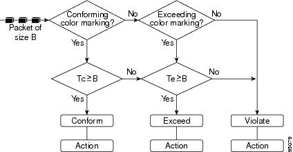
The flow chart in Figure 1 illustrates the algorithm used for handling traffic in color-aware single-rate traffic policing.
Figure 1 Traffic Flow Algorithm Used in Color-Aware Single-Rate Traffic Policing
In the above flow chart, a packet of size B arrives at the interface. Tc indicates the number of tokens in the CIR token bucket, and Tb indicates the number of tokens in the excess token bucket.
When a packet of size B bytes arrives at the interface, the packet is evaluated as to whether it is marked as either a conform-color packet, an exceed-color packet, or a packet with no color marking. Then the following actions are performed on the packet in the order shown below:
1.
2.
3.
Policing Actions
The algorithm provides users with three actions for each packet: a conform action, an exceed action, and an optional violate action. A conform action is applied to the conforming packets, an exceed action is applied to the exceeding packets, and an violate action is applied to the violating packets. Users can specify these actions. For instance, conforming packets can sent, exceeding packets can sent with a decreased priority, and violating packets can be dropped.
Color-Aware Mode of Two-Rate Traffic Policing
Networks police traffic by limiting the input or output transmission rate of a class of traffic on the basis of user-defined criteria. Policing traffic allows you to control the maximum rate of traffic sent or received on an interface and to partition a network into multiple priority levels or CoS.
With the two-rate traffic policing, you can enforce traffic policing according to two separate rates—the CIR and the PIR. You can specify the use of these two rates, along with their corresponding values, by using the cir and pir keywords of the police command.
Two-rate traffic policing uses two token buckets—Tc and Tp—for policing traffic at two independent rates. The Tc token bucket contains the tokens in the CIR bucket. The Tp token bucket contains the tokens in the PIR bucket.
Note the following points about the two token buckets:
•
•
Two-Rate Color-Aware Mode Functionality
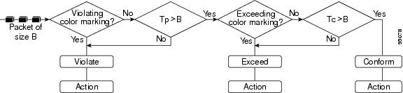
The flow chart in Figure 2 illustrates the algorithm used for handling traffic in color-aware two-rate traffic policing.
Figure 2 Traffic Flow Algorithm Used in Color-Aware Two-Rate Traffic Policing
In the above illustration, a packet of size B arrives at the interface. Tc indicates the number of tokens in the CIR token bucket, and Tp indicates the number of tokens in PIR token bucket.
When a packet of size B bytes arrives at the interface, the packet is evaluated as to whether it is marked as either an exceed-color packet or a violate-color packet. Then the following actions are performed on the packet in the order shown below:
1.
2.
3.
Policing Actions
The algorithm provides users with three actions for each packet: a conform action, an exceed action, and an optional violate action. A conform action is applied to the conforming packets, an exceed action is applied to the exceeding packets, and an violate action is applied to the violating packets. Users can specify these actions. For instance, conforming packets can sent, exceeding packets can sent with a decreased priority, and violating packets can be dropped.
Packet Matching Criteria
The first process in configuring color-aware policing is to create a class map. The class map is used to specify packet matching criteria.For instance, you can configure the class map to match packets based on a precedence level, a CoS value, or a differentiated services code point (DSCP) value. The match criteria is set with a specific match command. For example, to match packets based on a precedence value, use the match precedence command.
The match commands that can be used in a class map to establish packet matching criteria include the commands listed in Table 1.
.
The specific match commands that can be used to match packets vary from Cisco IOS release to Cisco IOS release. For more information about the match commands, refer to the documentation for your Cisco IOS release.
How to Configure Color-Aware Policing
This section contains the following procedures:
•
•
•
•
Creating a Class Map
A class map is used to specify packet matching criteria. To create a class map, use the commands in the following sections.
SUMMARY STEPS
1.
2.
3.
4.
5.
6.
7.
8.
DETAILED STEPS
Step 1
enable
Example:Router> enable
Enables privileged EXEC mode.
•
Step 2
configure terminal
Example:Router# configure terminal
Enters global configuration mode.
Step 3
class-map [match-all | match-any] class-map-name
Example:Router(config)# class-map conform_color_map
Creates the conform-color class-map used for specifying packet matching criterion and enters class-map configuration mode.
Note
•
Step 4
match [ip] precedence ip-precedence-value
Router(config-cmap)# match ip precedence 5
(Optional) Specifies the IP precedence value as the match criterion.
•
Note
Step 5
exit
Example:Router(config-cmap)# exit
(Optional) Exits class-map configuration mode.
Step 6
class-map [match-all | match-any] class-map-name
Example:Router(config)# class-map exceed_color_map
Creates the exceed-color class-map used for specifying packet matching criterion and enters class-map configuration mode.
Note
•
Step 7
match [ip] precedence ip-precedence-value
Router(config-cmap)# match ip precedence 3
(Optional) Specifies the IP precedence value as the match criterion.
•
Note
Step 8
exit
Example:Router(config-cmap)# exit
(Optional) Exits class-map configuration mode.
Configuring a Policy Map
A policy map determines the specific QoS feature that will be applied to the packets in a specific class. For instance, a policy map can be used to configure traffic shaping, Weight Random Early Detection (WRED), or, as in this case, color-aware traffic policing.
To configure a policy map for color-aware traffic policing, use the commands in the following sections:
SUMMARY STEPS
1.
2.
3.
4.
5.
6.
7.
DETAILED STEPS
Attaching the Policy Map
The policy map you have created must be attached to the appropriate interface or ATM permanent virtual circuit (PVC). For example, you may have to attach policy maps to either the input or the output interface on either the ingress or the egress router.
To attach a policy map to the appropriate interface or ATM PVC, use the commands in the following sections:
SUMMARY STEPS
1.
2.
3.
4.
5.
6.
DETAILED STEPS
Step 1
enable
Example:Router> enable
Enables privileged EXEC mode.
•
Step 2
configure terminal
Example:Router# configure terminal
Enters global configuration mode.
Step 3
interface type number [name-tag]
Example:Router(config)# interface FastEthernet1/0.1
Configures the interface type specified and enters interface configuration mode.
•
Step 4
pvc [name] vpi/vci [ilmi | qsaal | smds]
Example:Router(config-if)# pvc cisco 0/16 ilmi
(Optional) Creates or assigns a name to an ATM PVC, specifies the encapsulation type on an ATM PVC, and enters ATM VC configuration mode.
Note
•
Step 5
service-policy {input | output} policy-map-name
Example:Router(config-if)# service-policy input policy1
Specifies the name of the policy map to be attached to the input or output direction of the interface.
Note
•
Step 6
exit
Example:Router(config-if)# exit
(Optional) Exits interface configuration mode.
Verifying the Configuration
This task allows you to verify that you created the configuration you intended and that the feature is functioning correctly. To verify the configuration, use the commands in the following sections:
SUMMARY STEPS
1.
2.
3.
4.
DETAILED STEPS
Troubleshooting Tips
The commands in the "Verifying the Configuration" section allow you to verify that you achieved the intended configuration and that the feature is functioning correctly. If after using the show commands listed above, the configuration is not correct or the feature is not functioning as expected, do the following.
If the configuration is not the one you intended, complete the following procedures:
•
•
•
If the packets are not being matched correctly (for example, the packet counters are not incrementing correctly), complete the following procedures:
•
•
•
–
–
Configuration Examples for Color-Aware Policing
This section provides the following configuration example:
•
Color-Aware Policing: Example
The following example shows color-aware policing configured in a policy map called "color." Before the feature was configured, the class-map command was used to create two classes called "c1" and "c2," respectively. These two classes were configured as shown below:
class-map c1match ip prec 5class-map c2match ip prec 3With the two classes created, color-aware policing is configured as shown below:
Router# enableRouter# configure terminalRouter(config)# policy-map colorRouter(config-pmap)# class ccolorRouter(config-pmap-c)# police cir 8000 bc 5000 pir 8000 be 5000 conform-action transmit exceed-action set-prec-transmit 4 violate-action dropRouter(config-pmap-c-police)# conform-color c1 exceed-color c2
Note
With color-aware policing configured as shown, the following results occur based on the CIR, the PIR, and the conform actions, exceed actions, and violate actions specified by the police command:
•
•
•
Additional References
The following sections provide references related to the Color-Aware Policing feature:
Related Documents
QoS commands: complete command syntax, command modes, command history, defaults, usage guidelines, and examples
Cisco IOS Quality of Service Solutions Command Reference, Release 12.3T
Additional information about configuring traffic policing
"Policing and Shaping" chapter in Cisco IOS Quality of Service Solutions Configuration Guide, Release 12.3
MQC
"Configuring the Modular Quality of Service Command-Line Interface" chapter in Cisco IOS Quality of Service Solutions Configuration Guide, Release 12.3
Two-rate traffic policing
"Two-Rate Policer" Cisco IOS Release 12.2(4)T feature module
Traffic policing using multiple policer actions
Policer Enhancement — Multiple Actions, Cisco IOS Release 12.2(8)T feature module
Percentage-based traffic policing and shaping
Percentage-Based Policing and Shaping, Cisco IOS Release 12.2(13)T feature module
Three-level hierarchical policing
Modular QoS CLI (MQC) Three-Level Hierarchical Policer, Cisco IOS Release 12.2(13)T feature module
Standards
MIBs
RFCs
Technical Assistance
Command Reference
This section documents new and modified commands. All other commands used with this feature are documented in the Cisco IOS Release 12.3T command reference publications.
New Commands
Modified Commands
conform-color
To enable color-aware traffic policing and create the conform-color and exceed-color class maps used for color-aware traffic policing, use the conform-color command in policy-map class police configuration mode. To disable the color-aware mode of traffic policing, use the no form of this command.
conform-color class-map-name [exceed-color class-map-name]
no conform-color
Syntax Description
Defaults
No default behavior or values
Command Modes
Policy-map class police configuration
Command History
12.0(26)S
This command was introduced.
12.2(28)SB
This command was integrated into Cisco IOS Release 12.2(28)SB.
Usage Guidelines
The conform-color command is used in conjunction with the police command to configure color-aware policing. The police command specifies the committed information rate (CIR), conform burst (bc) size, peak information rate (PIR), and excess burst (be) size used to police packets. The police command is also used to specify any optional policing actions (such as transmit, set-clp-transmit, or drop) that can be performed on packets conforming to, exceeding, or violating the specified rates.
When using the conform-color command, note the following points:
•
•
Examples
The following example shows color-aware policing configured in a policy map called "color." Before the feature was configured, the class-map command was used to create two classes called "c1" and "c2," respectively. These two classes were configured as shown below:
class-map c1match ip prec 5class-map c2match ip prec 3With the two classes created, color-aware policing is configured as shown below:
Router# enableRouter# configure terminalRouter(config)# policy-map colorRouter(config-pmap)# class ccolorRouter(config-pmap-c)# police cir 8000 bc 5000 pir 8000 be 5000 conform-action transmit exceed-action set-prec-transmit 4 violate-action dropRouter(config-pmap-c-police)# conform-color c1 exceed-color c2With color-aware policing configured as shown, the following results occur on the basis of the CIR, the PIR, and the conform actions, exceed actions, and violate actions specified by the police command:
•
•
•
Related Commands
show policy-map
To display the configuration of all classes for a specified service policy map or all classes for all existing policy maps, use the show policy-map command in EXEC mode.
show policy-map [policy-map]
Syntax Description
policy-map
(Optional) Name of the service policy map whose complete configuration is to be displayed.
Command Default
All existing policy map configurations are displayed.
Command Modes
EXEC
Command History
Usage Guidelines
The show policy-map command displays the configuration of a service policy map created using the policy-map command. You can use the show policy-map command to display all class configurations comprising any existing service policy map, whether or not that service policy map has been attached to an interface.
Examples
The following is sample output from the show policy-map command. This sample output displays the contents of a policy map called "policy1." In policy 1, traffic policing on the basis of a committed information rate (CIR) of 20 percent has been configured, and the bc and be have been specified in milliseconds. As part of the traffic policing configuration, optional conform, exceed, and violate actions have been specified.
Router# show policy-map policy1Policy Map policy1Class class1police cir percent 20 bc 300 ms pir percent 40 be 400 msconform-action transmitexceed-action dropviolate-action dropTable 2 describes the significant fields shown in the display.
Related Commands
show policy-map interface
To display the packet statistics of all classes that are configured for all service policies either on the specified interface or subinterface or on a specific permanent virtual circuit (PVC) on the interface, use the show policy-map interface command in privileged EXEC mode.
show policy-map interface [type access-control] interface-name [vc [vpi/] vci] [dlci dlci]
[input | output]ATM Shared Port Adapter
show policy-map interface atm slot/subslot/port[.subinterface]
Syntax Description
Defaults
The absence of both the forward slash (/) and a vpi value defaults the vpi value to 0. If this value is omitted, information for all virtual circuits (VCs) on the specified ATM interface or subinterface is displayed.
ATM Shared Port Adapter
When used with the ATM shared port adapter, this command has no default behavior or values.
Command Modes
Privileged EXEC
ATM Shared Port Adapter
When used with the ATM shared port adapter, EXEC or privileged EXEC.
Command History
Usage Guidelines
The show policy-map interface command displays the packet statistics for classes on the specified interface or the specified PVC only if a service policy has been attached to the interface or the PVC.
You can use the interface-name argument to display output for a PVC only for enhanced ATM port adapters (PA-A3) that support per-VC queueing.
The counters displayed after the show policy-map interface command is entered are updated only if congestion is present on the interface.
The show policy-map interface command displays policy information about Frame Relay PVCs only if Frame Relay Traffic Shaping (FRTS) is enabled on the interface.
The show policy-map interface command displays ECN marking information only if ECN is enabled on the interface.
To determine if shaping is active with HQF, check the queue depth field of the "(queue depth/total drops/no-buffer drops)" line in the show policy-map interface command output.
Examples
This section provides sample output from typical show policy-map interface commands. Depending upon the interface in use and the options enabled, the output you see may vary slightly from the ones shown below.
Example of Weighted Fair Queueing (WFQ) on Serial Interface
The following sample output of the show policy-map interface command displays the statistics for the serial 3/1 interface, to which a service policy called mypolicy (configured as shown below) is attached. Weighted fair queueing (WFQ) has been enabled on this interface. See Table 3 for an explanation of the significant fields that commonly appear in the command output.
policy-map mypolicyclass voicepriority 128class goldbandwidth 100class silverbandwidth 80random-detectRouter# show policy-map interface serial3/1 outputSerial3/1Service-policy output: mypolicyClass-map: voice (match-all)0 packets, 0 bytes5 minute offered rate 0 bps, drop rate 0 bpsMatch: ip precedence 5Weighted Fair QueueingStrict PriorityOutput Queue: Conversation 264Bandwidth 128 (kbps) Burst 3200 (Bytes)(pkts matched/bytes matched) 0/0(total drops/bytes drops) 0/0Class-map: gold (match-all)0 packets, 0 bytes5 minute offered rate 0 bps, drop rate 0 bpsMatch: ip precedence 2Weighted Fair QueueingOutput Queue: Conversation 265Bandwidth 100 (kbps) Max Threshold 64 (packets)(pkts matched/bytes matched) 0/0(depth/total drops/no-buffer drops) 0/0/0Class-map: silver (match-all)0 packets, 0 bytes5 minute offered rate 0 bps, drop rate 0 bpsMatch: ip precedence 1Weighted Fair QueueingOutput Queue: Conversation 266Bandwidth 80 (kbps)(pkts matched/bytes matched) 0/0(depth/total drops/no-buffer drops) 0/0/0exponential weight: 9mean queue depth: 0class Transmitted Random drop Tail drop Minimum Maximum Markpkts/bytes pkts/bytes pkts/bytes thresh thresh prob0 0/0 0/0 0/0 20 40 1/101 0/0 0/0 0/0 22 40 1/102 0/0 0/0 0/0 24 40 1/103 0/0 0/0 0/0 26 40 1/104 0/0 0/0 0/0 28 40 1/105 0/0 0/0 0/0 30 40 1/106 0/0 0/0 0/0 32 40 1/107 0/0 0/0 0/0 34 40 1/10rsvp 0/0 0/0 0/0 36 40 1/10Class-map: class-default (match-any)0 packets, 0 bytes5 minute offered rate 0 bps, drop rate 0 bpsMatch: anyExample of Traffic Shaping on Serial Interface
The following sample output from the show policy-map interface command displays the statistics for the serial 3/2 interface, to which a service policy called p1 (configured as shown below) is attached. Traffic shaping has been enabled on this interface. See Table 3 for an explanation of the significant fields that commonly appear in the command output.
policy-map p1class c1shape average 320000Router# show policy-map interface serial3/2 outputSerial3/2Service-policy output: p1Class-map: c1 (match-all)0 packets, 0 bytes5 minute offered rate 0 bps, drop rate 0 bpsMatch: ip precedence 0Traffic ShapingTarget Byte Sustain Excess Interval Increment AdaptRate Limit bits/int bits/int (ms) (bytes) Active320000 2000 8000 8000 25 1000 -Queue Packets Bytes Packets Bytes ShapingDepth Delayed Delayed Active0 0 0 0 0 noClass-map: class-default (match-any)0 packets, 0 bytes5 minute offered rate 0 bps, drop rate 0 bpsMatch: anyTable 3 describes significant fields commonly shown in the displays. The fields in the table are grouped according to the relevant QoS feature.
Table 3 show policy-map interface Field Descriptions 1
Service-policy output
Name of the output service policy applied to the specified interface or VC.
Class-map
Class of traffic being displayed. Output is displayed for each configured class in the policy. The choice for implementing class matches (for example, match-all or match-any) can also appear next to the traffic class.
packets and bytes
Number of packets (also shown in bytes) identified as belonging to the class of traffic being displayed.
offered rate
Rate, in kbps, of packets coming in to the class.
Note
drop rate
Rate, in kbps, at which packets are dropped from the class. The drop rate is calculated by subtracting the number of successfully transmitted packets from the offered rate.
Note
Match
Match criteria specified for the class of traffic. Choices include criteria such as IP precedence, IP differentiated services code point (DSCP) value, Multiprotocol Label Switching (MPLS) experimental (EXP) value, access groups, and QoS groups. For more information about the variety of match criteria options available, refer to the chapter "Configuring the Modular Quality of Service Command-Line Interface" in the Cisco IOS Quality of Service Solutions Configuration Guide.
Output Queue
The weighted fair queueing (WFQ) conversation to which this class of traffic is allocated.
Bandwidth
Bandwidth, in either kbps or percentage, configured for this class and the burst size.
pkts matched/bytes matched
Number of packets (also shown in bytes) matching this class that were placed in the queue. This number reflects the total number of matching packets queued at any time. Packets matching this class are queued only when congestion exists. If packets match the class but are never queued because the network was not congested, those packets are not included in this total. However, if process switching is in use, the number of packets is always incremented even if the network is not congested.
depth/total drops/no-buffer drops
Number of packets discarded for this class. No-buffer indicates that no memory buffer exists to service the packet.
exponential weight
Exponent used in the average queue size calculation for a WRED parameter group.
mean queue depth
Average queue depth based on the actual queue depth on the interface and the exponential weighting constant. It is a fluctuating average. The minimum and maximum thresholds are compared against this value to determine drop decisions.
class
IP precedence level.
Transmitted pkts/bytes
Number of packets (also shown in bytes) passed through WRED and not dropped by WRED.
Note
Random drop pkts/bytes
Number of packets (also shown in bytes) randomly dropped when the mean queue depth is between the minimum threshold value and the maximum threshold value for the specified IP precedence level.
Tail drop pkts/bytes
Number of packets dropped when the mean queue depth is greater than the maximum threshold value for the specified IP precedence level.
Minimum thresh
Minimum threshold. Minimum WRED threshold in number of packets.
Maximum thresh
Maximum threshold. Maximum WRED threshold in number of packets.
Mark prob
Mark probability. Fraction of packets dropped when the average queue depth is at the maximum threshold.
Target Rate
Rate used for shaping traffic.
Byte Limit
Maximum number of bytes that can be transmitted per interval. Calculated as follows:
((Bc+Be) /8) x 1
Sustain bits/int
Committed burst (Bc) rate.
Excess bits/int
Excess burst (Be) rate.
Interval (ms)
Time interval value in milliseconds (ms).
Increment (bytes)
Number of credits (in bytes) received in the token bucket of the traffic shaper during each time interval.
Queue Depth
Current queue depth of the traffic shaper.
Packets
Total number of packets that have entered the traffic shaper system.
Bytes
Total number of bytes that have entered the traffic shaper system.
Packets Delayed
Total number of packets delayed in the queue of the traffic shaper before being transmitted.
Bytes Delayed
Total number of bytes delayed in the queue of the traffic shaper before being transmitted.
Shaping Active
Indicates whether the traffic shaper is active. For example, if a traffic shaper is active, and the traffic being sent exceeds the traffic shaping rate, a "yes" appears in this field.
1 A number in parentheses may appear next to the service-policy output name, class-map name, and match criteria information. The number is for Cisco internal use only and can be disregarded.
Example of Precedence-Based Aggregate WRED on ATM Shared Port Adapter
The following sample output of the show policy-map interface command displays the statistics for the ATM shared port adapter interface 4/1/0.10, to which a service policy called prec-aggr-wred (configured as shown below) is attached. Because aggregate WRED has been enabled on this interface, the class through Mark Prob statistics are aggregated by subclasses. See Table 4 for an explanation of the significant fields that commonly appear in the command output.
Router(config)# policy-map prec-aggr-wredRouter(config-pmap)# class class-defaultRouter(config-pmap-c)# random-detect aggregateRouter(config-pmap-c)# random-detect precedence values 0 1 2 3 minimum thresh 10 maximum-thresh 100 mark-prob 10Router(config-pmap-c)# random-detect precedence values 4 5 minimum-thresh 40 maximum-thresh 400 mark-prob 10Router(config-pmap-c)# random-detect precedence values 6 minimum-thresh 60 maximum-thresh 600 mark-prob 10Router(config-pmap-c)# random-detect precedence values 7 minimum-thresh 70 maximum-thresh 700 mark-prob 10Router(config-pmap-c)# interface ATM4/1/0.10 point-to-pointRouter(config-subif)# ip address 10.0.0.2 255.255.255.0Router(config-subif)# pvc 10/110Router(config-subif)# service-policy output prec-aggr-wred
Router# show policy-map interface a4/1/0.10ATM4/1/0.10: VC 10/110 -Service-policy output: prec-aggr-wredClass-map: class-default (match-any)0 packets, 0 bytes5 minute offered rate 0 bps, drop rate 0 bpsMatch: anyExp-weight-constant: 9 (1/512)Mean queue depth: 0class Transmitted Random drop Tail drop Minimum Maximum Markpkts/bytes pkts/bytes pkts/bytes thresh thresh prob0 1 2 3 0/0 0/0 0/0 10 100 1/104 5 0/0 0/0 0/0 40 400 1/106 0/0 0/0 0/0 60 600 1/107 0/0 0/0 0/0 70 700 1/10Example of DSCP-Based Aggregate WRED on ATM Shared Port Adapter
The following sample output of the show policy-map interface command displays the statistics for the ATM shared port adapter interface 4/1/0.11, to which a service policy called dscp-aggr-wred (configured as shown below) is attached. Because aggregate WRED has been enabled on this interface, the class through Mark Prob statistics are aggregated by subclasses. See Table 4 for an explanation of the significant fields that commonly appear in the command output.
Router(config)# policy-map dscp-aggr-wredRouter(config-pmap)# class class-defaultRouter(config-pmap-c)# random-detect dscp-based aggregate minimum-thresh 1 maximum-thresh 10 mark-prob 10Router(config-pmap-c)# random-detect dscp values 0 1 2 3 4 5 6 7 minimum-thresh 10 maximum-thresh 20 mark-prob 10Router(config-pmap-c)# random-detect dscp values 8 9 10 11 minimum-thresh 10 maximum-thresh 40 mark-prob 10Router(config)# interface ATM4/1/0.11 point-to-pointRouter(config-subif)# ip address 10.0.0.2 255.255.255.0Router(config-subif)# pvc 11/101Router(config-subif)# service-policy output dscp-aggr-wred
Router# show policy-map interface a4/1/0.11ATM4/1/0.11: VC 11/101 -Service-policy output: dscp-aggr-wredClass-map: class-default (match-any)0 packets, 0 bytes5 minute offered rate 0 bps, drop rate 0 bpsMatch: anyExp-weight-constant: 0 (1/1)Mean queue depth: 0class Transmitted Random drop Tail drop Minimum Maximum Markpkts/bytes pkts/bytes pkts/bytes thresh thresh probdefault 0/0 0/0 0/0 1 10 1/100 1 2 34 5 6 7 0/0 0/0 0/0 10 20 1/108 9 10 11 0/0 0/0 0/0 10 40 1/10Table 4 describes the significant fields shown in the display when aggregate WRED is configured for an ATM shared port adapter.
Frame Relay Voice-Adaptive Traffic-Shaping show policy interface Command Example
The following sample output shows that Frame Relay voice-adaptive traffic shaping is currently active and has 29 seconds left on the deactivation timer. With traffic shaping active and the deactivation time set, this means that the current sending rate on DLCI 201 is minCIR, but if no voice packets are detected for 29 seconds, the sending rate will increase to CIR.
Router# show policy interface Serial3/1.1Serial3/1.1:DLCI 201 -Service-policy output:MQC-SHAPE-LLQ1Class-map:class-default (match-any)1434 packets, 148751 bytes30 second offered rate 14000 bps, drop rate 0 bpsMatch:anyTraffic ShapingTarget/Average Byte Sustain Excess Interval IncrementRate Limit bits/int bits/int (ms) (bytes)63000/63000 1890 7560 7560 120 945Adapt Queue Packets Bytes Packets Bytes ShapingActive Depth Delayed Delayed ActiveBECN 0 1434 162991 26 2704 yesVoice Adaptive Shaping active, time left 29 secsTable 5 describes the significant fields shown in the display. Significant fields that are not described in Table 5 are described in Table 3, "show policy-map interface Field Descriptions."
Two-Rate Traffic Policing show policy-map interface Command Example
The following is sample output from the show policy-map interface command when two-rate traffic policing has been configured. In the example below, 1.25 Mbps of traffic is sent ("offered") to a policer class.
Router# show policy-map interface serial3/0Serial3/0Service-policy output: policy1Class-map: police (match all)148803 packets, 36605538 bytes30 second offered rate 1249000 bps, drop rate 249000 bpsMatch: access-group 101police:cir 500000 bps, conform-burst 10000, pir 1000000, peak-burst 100000conformed 59538 packets, 14646348 bytes; action: transmitexceeded 59538 packets, 14646348 bytes; action: set-prec-transmit 2violated 29731 packets, 7313826 bytes; action: dropconformed 499000 bps, exceed 500000 bps violate 249000 bpsClass-map: class-default (match-any)19 packets, 1990 bytes30 seconds offered rate 0 bps, drop rate 0 bpsMatch: anyThe two-rate traffic policer marks 500 kbps of traffic as conforming, 500 kbps of traffic as exceeding, and 250 kbps of traffic as violating the specified rate. Packets marked as conforming will be sent as is, and packets marked as exceeding will be marked with IP Precedence 2 and then sent. Packets marked as violating the specified rate are dropped.
Table 6 describes the significant fields shown in the display.
Multiple Traffic Policing Actions show policy-map interface Command Example
The following is sample output from the show policy-map command when the Policer Enhancement — Multiple Actions feature has been configured. The sample output from the show policy-map interface command displays the statistics for the serial 3/2 interface, to which a service policy called "police" (configured as shown below) is attached.
policy-map policeclass class-defaultpolice cir 1000000 pir 2000000conform-action transmitexceed-action set-prec-transmit 4exceed-action set-frde-transmitviolate-action set-prec-transmit 2violate-action set-frde-transmitRouter# show policy-map interface serial3/2Serial3/2: DLCI 100 -Service-policy output: policeClass-map: class-default (match-any)172984 packets, 42553700 bytes5 minute offered rate 960000 bps, drop rate 277000 bpsMatch: anypolice:cir 1000000 bps, bc 31250 bytes, pir 2000000 bps, be 31250 bytesconformed 59679 packets, 14680670 bytes; actions:transmitexceeded 59549 packets, 14649054 bytes; actions:set-prec-transmit 4set-frde-transmitviolated 53758 packets, 13224468 bytes; actions:set-prec-transmit 2set-frde-transmitconformed 340000 bps, exceed 341000 bps, violate 314000 bpsThe sample output from show policy-map interface command shows the following:
•
•
•
Note
Table 7 describes the significant fields shown in the display.
Explicit Congestion Notification show policy-map interface Command Example
The following is sample output from the show policy-map interface command when the WRED — Explicit Congestion Notification (ECN) feature has been configured. The words "explicit congestion notification" included in the output indicate that ECN has been enabled.
Router# show policy-map interface Serial4/1Serial4/1Service-policy output:policy_ecnClass-map:prec1 (match-all)1000 packets, 125000 bytes30 second offered rate 14000 bps, drop rate 5000 bpsMatch:ip precedence 1Weighted Fair QueueingOutput Queue:Conversation 42Bandwidth 20 (%)Bandwidth 100 (kbps)(pkts matched/bytes matched) 989/123625(depth/total drops/no-buffer drops) 0/455/0exponential weight:9explicit congestion notificationmean queue depth:0class Transmitted Random drop Tail drop Minimum Maximum Markpkts/bytes pkts/bytes pkts/bytes threshold threshold probability0 0/0 0/0 0/0 20 40 1/101 545/68125 0/0 0/0 22 40 1/102 0/0 0/0 0/0 24 40 1/103 0/0 0/0 0/0 26 40 1/104 0/0 0/0 0/0 28 40 1/105 0/0 0/0 0/0 30 40 1/106 0/0 0/0 0/0 32 40 1/107 0/0 0/0 0/0 34 40 1/10rsvp 0/0 0/0 0/0 36 40 1/10class ECN Markpkts/bytes0 0/01 43/53752 0/03 0/04 0/05 0/06 0/07 0/0rsvp 0/0Table 8 describes the significant fields shown in the display.
Class-Based RTP and TCP Header Compression show policy-map interface Command Example
The following sample output from the show policy-map interface command shows the RTP header compression has been configured for a class called "prec2" in the policy map called "p1".
The show policy-map interface command output displays the type of header compression configured (RTP), the interface to which the policy map called "p1" is attached (Serial 4/1), the total number of packets, the number of packets compressed, the number of packets saved, the number of packets sent, and the rate at which the packets were compressed (in bits per second (bps)).
In this example, User Datagram Protocol (UDP)/RTP header compressions have been configured, and the compression statistics are included at the end of the display.
Router# show policy-map interface Serial4/1Serial4/1Service-policy output:p1Class-map:class-default (match-any)1005 packets, 64320 bytes30 second offered rate 16000 bps, drop rate 0 bpsMatch:anycompress:header ip rtpUDP/RTP Compression:Sent:1000 total, 999 compressed,41957 bytes saved, 17983 bytes sent3.33 efficiency improvement factor99% hit ratio, five minute miss rate 0 misses/sec, 0 maxrate 5000 bpsTable 9 describes the significant fields shown in the display.
Table 9 show policy-map interface Field Descriptions—Configured for Class-Based RTP and TCP Header Compression1
Service-policy output
Name of the output service policy applied to the specified interface or VC.
Class-map
Class of traffic being displayed. Output is displayed for each configured class in the policy. The choice for implementing class matches (for example, match-all or match-any) can also appear next to the traffic class.
packets, bytes
Number of packets (also shown in bytes) identified as belonging to the class of traffic being displayed.
offered rate
Rate, in kbps, of packets coming in to the class.
Note
UDP/RTP Compression
Indicates that RTP header compression has been configured for the class.
Sent total
Count of every packet sent, both compressed packets and full-header packets.
Sent compressed
Count of number of compressed packets sent.
bytes saved
Total number of bytes saved (that is, bytes not needing to be sent).
bytes sent
Total number of bytes sent for both compressed and full-header packets.
efficiency improvement factor
The percentage of increased bandwidth efficiency as a result of header compression. For example, with RTP streams, the efficiency improvement factor can be as much as 2.9 (or 290 percent).
hit ratio
Used mainly for troubleshooting purposes, this is the percentage of packets found in the context database. In most instances, this percentage should be high.
five minute miss rate
The number of new traffic flows found in the last five minutes.
misses/sec
maxThe average number of new traffic flows found per second, and the highest rate of new traffic flows to date.
rate
The actual traffic rate (in bits per second) after the packets are compressed.
1 A number in parentheses may appear next to the service-policy output name and the class-map name. The number is for Cisco internal use only and can be disregarded.
Modular QoS CLI (MQC) Unconditional Packet Discard show policy-map interface Command Example
The following sample output from the show policy-map interface command displays the statistics for the Serial2/0 interface, to which a policy map called "policy1" is attached. The discarding action has been specified for all the packets belonging to a class called "c1." In this example, 32000 bps of traffic is sent ("offered") to the class and all of them are dropped. Therefore, the drop rate shows 32000 bps.
Router# show policy-map interface Serial2/0Serial2/0Service-policy output: policy1Class-map: c1 (match-all)10184 packets, 1056436 bytes5 minute offered rate 32000 bps, drop rate 32000 bpsMatch: ip precedence 0dropTable 10 describes the significant fields shown in the display.
Table 10 show policy-map interface Field Descriptions—Configured for MQC Unconditional Packet Discard1
Service-policy output
Name of the output service policy applied to the specified interface or VC.
Class-map
Class of traffic being displayed. Output is displayed for each configured class in the policy. The choice for implementing class matches (for example, match-all or match-any) can also appear next to the traffic class.
packets, bytes
Number of packets (also shown in bytes) identified as belonging to the class of traffic being displayed.
offered rate
Rate, in kbps, of packets coming in to the class.
Note
drop rate
Rate, in kbps, at which packets are dropped from the class. The drop rate is calculated by subtracting the number of successfully transmitted packets from the offered rate.
Note
Match
Match criteria specified for the class of traffic. Choices include criteria such as the Layer 3 packet length, IP precedence, IP DSCP value, MPLS experimental value, access groups, and QoS groups. For more information about the variety of match criteria options available, refer to the chapter "Configuring the Modular Quality of Service Command-Line Interface" in the Cisco IOS Quality of Service Solutions Configuration Guide.
drop
Indicates that the packet discarding action for all the packets belonging to the specified class has been configured.
1 A number in parentheses may appear next to the service-policy output name and the class-map name. The number is for Cisco internal use only and can be disregarded.
Percentage-Based Policing and Shaping show policy-map interface Command Example
The following sample output from the show policy-map interface command shows traffic policing configured using a CIR based on a bandwidth of 20 percent. The CIR and committed burst (Bc) in milliseconds (ms) are included in the display.
Router# show policy-map interface Serial3/1Serial3/1Service-policy output: mypolicyClass-map: gold (match-any)0 packets, 0 bytes5 minute offered rate 0 bps, drop rate 0 bpsMatch: anypolice:cir 20 % bc 10 mscir 2000000 bps, bc 2500 bytespir 40 % be 20 mspir 4000000 bps, be 10000 bytesconformed 0 packets, 0 bytes; actions: transmit exceeded 0 packets, 0 bytes; actions: dropviolated 0 packets, 0 bytes; actions:dropconformed 0 bps, exceed 0 bps, violate 0 bpsTable 11 describes the significant fields shown in the display.
Table 11 show policy-map interface Field Descriptions—Configured for Percentage-Based Policing and Shaping1
Service-policy output
Name of the output service policy applied to the specified interface or VC.
Class-map
Class of traffic being displayed. Output is displayed for each configured class in the policy. The choice for implementing class matches (for example, match-all or match-any) can also appear next to the traffic class.
packets, bytes
Number of packets (also shown in bytes) identified as belonging to the class of traffic being displayed.
offered rate
Rate, in kbps, of packets coming in to the class.
Note
police
Indicates that traffic policing based on a percentage of bandwidth has been enabled. Also, displays the bandwidth percentage, the CIR, and the committed burst (Bc) size in ms.
conformed, actions
Displays the number of packets and bytes marked as conforming to the specified rates, and the action to be taken on those packets.
exceeded, actions
Displays the number of packets and bytes marked as exceeding the specified rates, and the action to be taken on those packets.
1 A number in parentheses may appear next to the service-policy output name and the class-map name. The number is for Cisco internal use only and can be disregarded.
Traffic Shaping show policy-map interface Command Example
The following sample output from the show policy-map interface command (shown below) displays the statistics for the serial 3/2 interface. Traffic shaping has been enabled on this interface, and an average rate of 20 percent of the bandwidth has been specified.
Router# show policy-map interface Serial3/2Serial3/2Service-policy output: p1Class-map: c1 (match-all)0 packets, 0 bytes5 minute offered rate 0 bps, drop rate 0 bpsMatch: anyTraffic ShapingTarget/Average Byte Sustain Excess Interval Increment AdaptRate Limit bits/int bits/int (ms) (bytes) Active 20 % 10 (ms) 20 (ms)201500/201500 1952 7808 7808 38 976 -Queue Packets Bytes Packets Bytes ShapingDepth Delayed Delayed Active0 0 0 0 0 noTable 12 describes the significant fields shown in the display.
Table 12 show policy-map interface Field Descriptions—Configured for Percentage-Based Policing and Shaping (with Traffic Shaping Enabled)1
Service-policy output
Name of the output service policy applied to the specified interface or VC.
Class-map
Class of traffic being displayed. Output is displayed for each configured class in the policy. The choice for implementing class matches (for example, match-all or match-any) can also appear next to the traffic class.
packets, bytes
Number of packets (also shown in bytes) identified as belonging to the class of traffic being displayed.
offered rate
Rate, in kbps, of packets coming in to the class.
Note
drop rate
Rate, in kbps, at which packets are dropped from the class. The drop rate is calculated by subtracting the number of successfully transmitted packets from the offered rate.
Match
Match criteria specified for the class of traffic. Choices include criteria such as the Layer 3 packet length, IP precedence, IP DSCP value, MPLS experimental value, access groups, and quality of service (QoS) groups. For more information about the variety of match criteria options that are available, refer to the chapter "Configuring the Modular Quality of Service Command-Line Interface" in the Cisco IOS Quality of Service Solutions Configuration Guide, Release 12.2.
Traffic Shaping
Indicates that traffic shaping based on a percentage of bandwidth has been enabled.
Target /Average Rate
Rate (percentage) used for shaping traffic and the number of packets meeting that rate.
Byte Limit
Maximum number of bytes that can be transmitted per interval. Calculated as follows:
((Bc+Be) /8 ) x 1
Sustain bits/int
Committed burst (Bc) rate.
Excess bits/int
Excess burst (Be) rate.
Interval (ms)
Time interval value in milliseconds (ms).
Increment (bytes)
Number of credits (in bytes) received in the token bucket of the traffic shaper during each time interval.
Adapt Active
Indicates whether adaptive shaping is enabled.
Queue Depth
Current queue depth of the traffic shaper.
Packets
Total number of packets that have entered the traffic shaper system.
Bytes
Total number of bytes that have entered the traffic shaper system.
Packets Delayed
Total number of packets delayed in the queue of the traffic shaper before being transmitted.
Bytes Delayed
Total number of bytes delayed in the queue of the traffic shaper before being transmitted.
Shaping Active
Indicates whether the traffic shaper is active. For example, if a traffic shaper is active, and the traffic being sent exceeds the traffic shaping rate, a "yes" appears in this field.
1 A number in parentheses may appear next to the service-policy output name, class-map name, and match criteria information. The number is for Cisco internal use only and can be disregarded.
Packet Classification Based on Layer 3 Packet Length show policy-map interface Command Example
The following sample output from the show policy-map interface command displays the packet statistics for the Ethernet4/1 interface, to which a service policy called "mypolicy" is attached. The Layer 3 packet length has been specified as a match criterion for the traffic in the class called "class1".
Router# show policy-map interface Ethernet4/1Ethernet4/1Service-policy input: mypolicyClass-map: class1 (match-all)500 packets, 125000 bytes5 minute offered rate 4000 bps, drop rate 0 bpsMatch: packet length min 100 max 300QoS Setqos-group 20Packets marked 500Table 13 describes the significant fields shown in the display.
Table 13 show policy-map interface Field Descriptions—Configured for Packet Classification Based on Layer 3 Packet Length1
Service-policy input
Name of the input service policy applied to the specified interface or VC.
Class-map
Class of traffic being displayed. Output is displayed for each configured class in the policy. The choice for implementing class matches (for example, match-all or match-any) can also appear next to the traffic class.
packets, bytes
Number of packets (also shown in bytes) identified as belonging to the class of traffic being displayed.
offered rate
Rate, in kbps, of packets coming in to the class.
Note
drop rate
Rate, in kbps, at which packets are dropped from the class. The drop rate is calculated by subtracting the number of successfully transmitted packets from the offered rate.
Match
Match criteria specified for the class of traffic. Choices include criteria such as the Layer 3 packet length, IP precedence, IP DSCP value, MPLS experimental value, access groups, and QoS groups.
QoS Set, qos-group, Packets marked
Indicates that class-based packet marking based on the QoS group has been configured. Includes the qos-group number and the number of packets marked.
1 A number in parentheses may appear next to the service-policy input name, class-map name, and match criteria information. The number is for Cisco internal use only and can be disregarded.
Enhanced Packet Marking show policy-map interface Command Example
The following sample output of the show policy-map interface command shows the service policies attached to a FastEthernet subinterface. In this example, a service policy called "policy1" has been attached. In "policy1", a table map called "table-map1" has been configured. The values in "table-map1" will be used to map the precedence values to the corresponding class of service (CoS) values.
Router# show policy-map interfaceFastEthernet1/0.1Service-policy input: policy1Class-map: class-default (match-any)0 packets, 0 bytes5 minute offered rate 0 bps, drop rate 0 bpsMatch: anyQoS Setprecedence cos table table-map1Packets marked 0Table 14 describes the fields shown in the display.
Table 14 show policy-map interface Field Descriptions—Configured for Enhanced Packet Marking 1
Service-policy input
Name of the input service policy applied to the specified interface or VC.
Class-map
Class of traffic being displayed. Output is displayed for each configured class in the policy. The choice for implementing class matches (for example, match-all or match-any) can also appear next to the traffic class.
packets, bytes
Number of the packets (also shown in bytes) identified as belonging to the class of traffic being displayed.
offered rate
Rate, in kbps, of the packets coming into the class.
Match
Match criteria specified for the class of traffic. Choices include criteria such as Precedence, IP differentiated services code point (DSCP) value, Multiprotocol Label Switching (MPLS) experimental value, access groups, and quality of service (QoS) group (set). For more information about the variety of match criteria options that are available, refer to the "Configuring the Modular Quality of Service Command-Line Interface" section in the Cisco IOS Quality of Service Solutions Configuration Guide.
QoS Set
Indicates that QoS group (set) has been configured for the particular class.
precedence cos table table-map1
Indicates that a table map (called "table-map1") has been used to determine the precedence value. The precedence value will be set according to the CoS value defined in the table map.
Packets marked
Total number of packets marked for the particular class.
1 A number in parentheses may appear next to the service-policy input name and the class-map name. The number is for Cisco internal use only and can be disregarded.
Traffic Policing show policy-map interface Command Example
The following is sample output from the show policy-map interface command. This sample displays the statistics for the serial 2/0 interface on which traffic policing has been enabled. The committed (conform) burst (bc) and excess (peak) burst (be) are specified in milliseconds (ms).
Router# show policy-map interface serial2/0Serial2/0Service-policy output: policy1 (1050)Class-map: class1 (match-all) (1051/1)0 packets, 0 bytes5 minute offered rate 0 bps, drop rate 0 bpsMatch: ip precedence 0 (1052)police:cir 20 % bc 300 mscir 409500 bps, bc 15360 bytespir 40 % be 400 mspir 819000 bps, be 40960 bytesconformed 0 packets, 0 bytes; actions:transmitexceeded 0 packets, 0 bytes; actions:dropviolated 0 packets, 0 bytes; actions:dropconformed 0 bps, exceed 0 bps, violate 0 bpsClass-map: class-default (match-any) (1054/0)0 packets, 0 bytes5 minute offered rate 0 bps, drop rate 0 bpsMatch: any (1055)0 packets, 0 bytes5 minute rate 0 bpsIn this example, the CIR and PIR are displayed in bps, and both the committed burst (bc) and excess burst (be) are displayed in bits.
The CIR, PIR bc, and be are calculated on the basis of the formulas described below.
Formula for Calculating the CIR
When calculating the CIR, the following formula is used:
•
According to the output from the show interfaces command for the serial 2/0 interface, the interface has a bandwidth (BW) of 2048 kbps.
Router # show interfaces serial2/0Serial2/0 is administratively down, line protocol is down Hardware is M4T MTU 1500 bytes, BW 2048 Kbit, DLY 20000 usec, rely 255/255, load 1/255The following values are used for calculating the CIR:
20 % * 2048 kbps = 409600 bps
Formula for Calculating the PIR
When calculating the PIR, the following formula is used:
•
According to the output from the show interfaces command for the serial 2/0 interface, the interface has a bandwidth (BW) of 2048 kbps.
Router # show interfaces serial2/0Serial2/0 is administratively down, line protocol is down Hardware is M4T MTU 1500 bytes, BW 2048 Kbit, DLY 20000 usec, rely 255/255, load 1/255The following values are used for calculating the PIR:
40 % * 2048 kbps = 819200 bps
Note
Formula for Calculating the Committed Burst (bc)
When calculating the bc, the following formula is used:
•
The following values are used for calculating the bc:
300 ms * 409600 bps = 15360 bytes
Formula for Calculating the Excess Burst (be)
When calculating the bc and the be, the following formula is used:
•
The following values are used for calculating the be:
400 ms * 819200 bps = 40960 bytes
Table 15 describes the significant fields shown in the display.
Table 15 show policy-map interface Field Descriptions
Service-policy output
Name of the output service policy applied to the specified interface or VC.
Class-map
Class of traffic being displayed. Output is displayed for each configured class in the policy. The choice for implementing class matches (for example, match-all or match-any) can also appear next to the traffic class.
packets and bytes
Number of packets (also shown in bytes) identified as belonging to the class of traffic being displayed.
offered rate
Rate, in kbps, of packets coming in to the class.
drop rate
Rate, in kbps, at which packets are dropped from the class. The drop rate is calculated by subtracting the number of successfully transmitted packets from the offered rate.
Match
Match criteria specified for the class of traffic. Choices include criteria such as the Layer 3 packet length, IP precedence, IP differentiated services code point (DSCP) value, Multiprotocol Label Switching (MPLS) experimental value, access groups, and quality of service (QoS) groups. For more information about the variety of match criteria options that are available, refer to the "Configuring the Modular Quality of Service Command-Line Interface" chapter of the Cisco IOS Quality of Service Solutions Configuration Guide.
police
Indicates that traffic policing has been enabled. Display includes the CIR, PIR (in both a percentage of bandwidth and in bps) and the bc and be in bytes and milliseconds. Also displays the optional conform, exceed, and violate actions, if any, and the statistics associated with these optional actions.
Bandwidth Estimation show policy-map interface Command Example
The following sample output from the show policy-map interface command displays statistics for the FastEthernet 0/1 interface on which bandwidth estimates for quality of service (QoS) targets have been generated.
The Bandwidth Estimation section indicates that bandwidth estimates for QoS targets have been defined. These targets include the packet loss rate, the packet delay rate, and the timeframe in milliseconds. Confidence refers to the drop-one-in value (as a percentage) of the targets. Corvil Bandwidth means the bandwidth estimate in kilobits per second.
When no drop or delay targets are specified, "none specified, falling back to drop no more than one packet in 500" appears in the output.
Router# show policy-map interface FastEthernet0/1FastEthernet0/1Service-policy output: my-policyClass-map: icmp (match-all)199 packets, 22686 bytes30 second offered rate 0 bps, drop rate 0 bpsMatch: access-group 101Bandwidth Estimation:Quality-of-Service targets:drop no more than one packet in 1000 (Packet loss < 0.10%)delay no more than one packet in 100 by 40 (or more) milliseconds(Confidence: 99.0000%)Corvil Bandwidth: 1 kbits/secClass-map: class-default (match-any)112 packets, 14227 bytes30 second offered rate 0 bps, drop rate 0 bpsMatch: anyBandwidth Estimation:Quality-of-Service targets:<none specified, falling back to drop no more than one packet in 500Corvil Bandwidth: 1 kbits/secShaping with HQF Enabled show policy-map interface Command Example
The following sample output from the show policy-map interface command shows that shaping is active (as seen in the queue depth field) with HQF enabled on the serial 4/3 interface. All traffic is classified to the class-default queue.
Router# show policy-map interface serial4/3Serial4/3Service-policy output: shapeClass-map: class-default (match-any)2203 packets, 404709 bytes30 second offered rate 74000 bps, drop rate 14000 bpsMatch: anyQueueingqueue limit 64 packets(queue depth/total drops/no-buffer drops) 64/354/0(pkts output/bytes output) 1836/337280shape (average) cir 128000, bc 1000, be 1000target shape rate 128000lower bound cir 0, adapt to fecn 0Service-policy : LLQqueue stats for all priority classes:queue limit 64 packets(queue depth/total drops/no-buffer drops) 0/0/0(pkts output/bytes output) 0/0Class-map: c1 (match-all)0 packets, 0 bytes30 second offered rate 0 bps, drop rate 0 bpsMatch: ip precedence 1Priority: 32 kbps, burst bytes 1500, b/w exceed drops: 0Class-map: class-default (match-any)2190 packets, 404540 bytes30 second offered rate 74000 bps, drop rate 14000 bpsMatch: anyqueue limit 64 packets(queue depth/total drops/no-buffer drops) 63/417/0(pkts output/bytes output) 2094/386300Related Commands
Any Internet Protocol (IP) addresses used in this document are not intended to be actual addresses. Any examples, command display output, and figures included in the document are shown for illustrative purposes only. Any use of actual IP addresses in illustrative content is unintentional and coincidental.
© 2003-2006 Cisco Systems, Inc. All rights reserved.