Feedback Feedback
|
Table Of Contents
MPLS Traffic Engineering—DiffServ Aware
Related Features and Technologies
The tunnel mpls traffic-eng bandwidth command
Level 1: Configuring the Device
Level 2: Configuring the Physical Interface
Level 3: Configuring the Tunnel Interface
Guaranteed Bandwidth Service Configuration
Guaranteed Bandwidth Service Examples
Example with Single Destination Prefix
Tunnel Midpoint Configuration [Mid-1]
Tunnel Midpoint Configuration [Mid-2]
Example with Many Destination Prefixes
Configuration of Tunnel Head-1
Configuration of Tunnel Head-2
Tunnel Midpoint Configuration [Mid-1]
Tunnel Midpoint Configuration [Mid-2]
debug mpls traffic-eng link-management preemption
mpls traffic-eng administrative-weight
mpls traffic-eng attribute-flags
mpls traffic-eng backup-path tunnel
mpls traffic-eng flooding thresholds
mpls traffic-eng link timers bandwidth-hold
mpls traffic-eng link timers periodic-flooding
mpls traffic-eng reoptimize timers frequency
mpls traffic-eng tunnels (global configuration)
mpls traffic-eng tunnels (interface configuration)
show mpls traffic-eng autoroute
show mpls traffic-eng fast-reroute database
show mpls traffic-eng fast-reroute log reroutes
show mpls traffic-eng link-management admission-control
show mpls traffic-eng link-management advertisements
show mpls traffic-eng link-management bandwidth-allocation
show mpls traffic-eng link-management igp-neighbors
show mpls traffic-eng link-management interfaces
show mpls traffic-eng link-management summary
show mpls traffic-eng topology
tunnel mpls traffic-eng affinity
tunnel mpls traffic-eng autoroute announce
tunnel mpls traffic-eng autoroute metric
tunnel mpls traffic-eng bandwidth
tunnel mpls traffic-eng fast-reroute
tunnel mpls traffic-eng path-option
tunnel mpls traffic-eng priority
MPLS Traffic Engineering—DiffServ Aware
First Published: 12.0(11) STLast Updated: February 28, 2006This guide presents extensions made to Multiprotocol Label Switching Traffic Engineering (MPLS TE) that make it DiffServ aware. Specifically, the bandwidth reservable on each link for constraint-based routing (CBR) purposes can now be managed through two bandwidth pools: a global pool and a sub-pool. The sub-pool can be limited to a smaller portion of the link bandwidth. Tunnels using the sub-pool bandwidth can then be used in conjunction with MPLS Quality of Service (QoS) mechanisms to deliver guaranteed bandwidth services end-to-end across the network.
History for the MPLS Traffic Engineering—DiffServ Aware Feature
Finding Support Information for Platforms and Cisco IOS Software Images
Use Cisco Feature Navigator to find information about platform support and Cisco IOS software image support. Access Cisco Feature Navigator at http://www.cisco.com/go/fn. You must have an account on Cisco.com. If you do not have an account or have forgotten your username or password, click Cancel at the login dialog box and follow the instructions that appear.
Contents
Background and Overview
MPLS traffic engineering allows constraint-based routing of IP traffic. One of the constraints satisfied by CBR is the availability of required bandwidth over a selected path. DiffServ-aware Traffic Engineering extends MPLS traffic engineering to enable you to perform constraint-based routing of "guaranteed" traffic, which satisfies a more restrictive bandwidth constraint than that satisfied by CBR for regular traffic. The more restrictive bandwidth is termed a sub-pool, while the regular TE tunnel bandwidth is called the global pool. (The sub-pool is a portion of the global pool.) This ability to satisfy a more restrictive bandwidth constraint translates into an ability to achieve higher Quality of Service performance (in terms of delay, jitter, or loss) for the guaranteed traffic.
For example, DS-TE can be used to ensure that traffic is routed over the network so that, on every link, there is never more than 40 per cent (or any assigned percentage) of the link capacity of guaranteed traffic (for example, voice), while there can be up to 100 per cent of the link capacity of regular traffic. Assuming QoS mechanisms are also used on every link to queue guaranteed traffic separately from regular traffic, it then becomes possible to enforce separate "overbooking" ratios for guaranteed and regular traffic. (In fact, for the guaranteed traffic it becomes possible to enforce no overbooking at all—or even an underbooking—so that very high QoS can be achieved end-to-end for that traffic, even while for the regular traffic a significant overbooking continues to be enforced.)
Also, through the ability to enforce a maximum percentage of guaranteed traffic on any link, the network administrator can directly control the end-to-end QoS performance parameters without having to rely on over-engineering or on expected shortest path routing behavior. This is essential for transport of applications that have very high QoS requirements (such as real-time voice, virtual IP leased line, and bandwidth trading), where over-engineering cannot be assumed everywhere in the network.
DS-TE involves extending OSPF (Open Shortest Path First routing protocol), so that the available sub-pool bandwidth at each preemption level is advertised in addition to the available global pool bandwidth at each preemption level. And DS-TE modifies constraint-based routing to take this more complex advertised information into account during path computation.
Benefits
DiffServ-aware Traffic Engineering enables service providers to perform separate admission control and separate route computation for discrete subsets of traffic (for example, voice and data traffic).
Therefore, by combining DS-TE with other IOS features such as QoS, the service provider can:
•
Develop QoS services for end customers based on signaled rather than provisioned QoS
•
•
•
Related Features and Technologies
The DS-TE feature is related to OSPF, IS-IS, RSVP (Resource reSerVation Protocol), QoS, and MPLS traffic engineering. Cisco documentation for all of these features is listed in the next section.
Prerequisites
Your network must support the following Cisco IOS features in order to support guaranteed bandwidth services based on DiffServ-aware Traffic Engineering:
•
•
•
•
•
Configuration Tasks
This section lists the minimum set of commands you need to implement the DiffServ-aware Traffic Engineering feature—in other words, to establish a tunnel that reserves bandwidth from the sub-pool.
The subsequent "Configuration Examples" section on page 8 presents these same commands in context and shows how, by combining them with QoS commands, you can build guaranteed bandwidth services.
Central Commands for DS-TE
DS-TE commands were developed from the existing command set that configures MPLS traffic engineering. The only difference introduced to create DS-TE was the expansion of two commands:
•
•
The ip rsvp bandwidth command
The old command was
ip rsvp bandwidth x ywhere x = the size of the only possible pool, and y = the size of a single traffic flow (ignored by traffic engineering)
Now the extended command is
ip rsvp bandwidth x y sub-pool zwhere x = the size of the global pool, and z = the size of the sub-pool.
(Remember, the sub-pool's bandwidth is less than—because it is part of—the global pool's bandwidth.)
The tunnel mpls traffic-eng bandwidth command
The old command was
tunnel mpls traffic-eng bandwidth bwhere b = the amount of bandwidth this tunnel requires.
Now you specify from which pool (global or sub) the tunnel's bandwidth is to come. You can enter
tunnel mpls traffic-eng bandwidth sub-pool bThis indicates that the tunnel should use bandwidth from the sub-pool. Alternatively, you can enter
tunnel mpls traffic-eng bandwidth bThis indicates that the tunnel should use bandwidth from the global pool (the default).
The Configuration Procedure
To establish a sub-pool TE tunnel, you must enter configurations at three levels:
•
•
•
On the first two levels, you activate traffic engineering; on the third level—the tunnel interface—you establish the sub-pool tunnel. Therefore, it is only at the tunnel headend device that you need to configure all three levels. At the tunnel midpoints and tail, it is sufficient to configure the first two levels.
In the tables below, each command is explained in brief. For a more complete explanation of any command, refer to the page given in the right-hand column.
Level 1: Configuring the Device
At this level, you tell the device (router or switch router) to use accelerated packet-forwarding (known as Cisco Express Forwarding), MultiProtocol Label Switching (MPLS), traffic-engineering tunneling, and either the OSPF or IS-IS routing algorithm (Open Shortest Path First or Intermediate System to Intermediate System). This level is often called global configuration mode because the configuration is applied globally, to the entire device, rather than to a specific interface or routing instance. (These commands have not been modified from earlier releases of Cisco IOS.)
You enter the following commands:
Level 2: Configuring the Physical Interface
Having configured the device, you now must configure the interface on that device through which the tunnel will run. To do that, you first put the router into interface-configuration mode.
You then enable Resource Reservation Protocol. RSVP is used to signal (set up) a traffic engineering tunnel, and to tell devices along the tunnel path to reserve a specific amount of bandwidth for the traffic that will flow through that tunnel. It is with this command that you establish the maximum size of the sub-pool.
Finally, you enable the MPLS traffic engineering tunnel feature on this physical interface—and if you will be relying on the IS-IS routing protocol, you enable that as well.
To accomplish these tasks, you enter the following commands:
Level 3: Configuring the Tunnel Interface
Now you create a set of attributes for the tunnel itself; those attributes are configured on the "tunnel interface" (not to be confused with the physical interface just configured above).
The only command which was modified at this level for DS-TE is tunnel mpls traffic-eng bandwidth.
You enter the following commands:
Verifying the Configurations
To view the complete configuration you have entered, use the EXEC command show running-config and check its output display for correctness.
To check just one tunnel's configuration, enter show interfaces tunnel followed by the tunnel interface number. And to see that tunnel's RSVP bandwidth and flow, enter show ip rsvp interface followed by the name or number of the physical interface.
Here is an example of the information displayed by these two commands. To see an explanation of each field used in the following displays, refer to the show interfaces tunnel command and the show ip rsvp interface command.
GSR1#show interfaces tunnel 4Tunnel4 is up, line protocol is downHardware is Routing TunnelMTU 1500 bytes, BW 9 Kbit, DLY 500000 usec, rely 255/255, load 1/255Encapsulation TUNNEL, loopback not set, keepalive set (10 sec)Tunnel source 0.0.0.0, destination 0.0.0.0Tunnel protocol/transport GRE/IP, key disabled, sequencing disabledLast input never, output never, output hang neverLast clearing of "show interface" counters neverOutput queue 0/0, 0 drops; input queue 0/75, 0 dropsFive minute input rate 0 bits/sec, 0 packets/secFive minute output rate 0 bits/sec, 0 packets/sec0 packets input, 0 bytes, 0 no bufferReceived 0 broadcasts, 0 runts, 0 giants0 input errors, 0 CRC, 0 frame, 0 overrun, 0 ignored, 0 abort0 packets output, 0 bytes, 0 underruns0 output errors, 0 collisions, 0 interface resets, 0 restartsGSR1#show ip rsvp interface pos4/0interface allocated i/f max flow max sub maxPO4/0 300K 466500K 466500K 0MTo view all tunnels at once on the router you have configured, enter show mpls traffic-eng tunnels brief. The information displayed when tunnels are functioning properly looks like this:
GSR1#show mpls traffic-eng tunnels briefSignalling Summary:LSP Tunnels Process: runningRSVP Process: runningForwarding: enabledPeriodic reoptimization: every 3600 seconds, next in 3029 secondsTUNNEL NAME DESTINATION UP IF DOWN IF STATE/PROTGSR1_t0 192.168.1.13 - SR3/0 up/upGSR1_t1 192.168.1.13 - SR3/0 up/upGSR1_t2 192.168.1.13 - PO4/0 up/upDisplayed 3 (of 3) heads, 0 (of 0) midpoints, 0 (of 0) tailsWhen one or more tunnels is not functioning properly, the display could instead look like this. (In the following example, tunnels t0 and t1 are down, as indicated in the far right column).
GSR1#show mpls traffic-eng tunnels briefSignalling Summary:LSP Tunnels Process: runningRSVP Process: runningForwarding: enabledPeriodic reoptimization: every 3600 seconds, next in 2279 secondsTUNNEL NAME DESTINATION UP IF DOWN IF STATE/PROTGSR1_t0 192.168.1.13 - SR3/0 up/downGSR1_t1 192.168.1.13 - SR3/0 up/downGSR1_t2 192.168.1.13 - PO4/0 up/upDisplayed 3 (of 3) heads, 0 (of 0) midpoints, 0 (of 0) tailsTo find out why a tunnel is down, insert its name into this same command, after adding the keyword name and omitting the keyword brief. For example:
GSR1#show mpls traffic-eng tunnels name GSR1_t0Name:GSR1_t0 (Tunnel0) Destination:192.168.1.13Status:Admin:up Oper:down Path: not valid Signalling:connectedIf, as in this example, the Path is displayed as not valid, use the show mpls traffic-eng topology command to make sure the router has received the needed updates.
Additionally, you can use any of the following show commands to inspect particular aspects of the network, router, or interface concerned:
Configuration Examples
First this section presents the DS-TE configurations needed to create the sub-pool tunnel. Then it presents the more comprehensive design for building end-to-end guaranteed bandwidth service, which involves configuring Quality of Service as well.
As shown in Figure 1, the tunnel configuration involves at least three devices—tunnel head, midpoint, and tail. On each of those devices one or two network interfaces must be configured, for traffic ingress and egress.
Figure 1 Sample Tunnel Topology
Tunnel Head
At the device level:
router-1# configure terminalEnter configuration commands, one per line. End with CNTL/Z.router-1(config)# ip cef distributedrouter-1(config)# mpls traffic-eng tunnels[now one uses either the IS-IS commands on the left or the OSPF commands on the right]
:
[now one resumes the common command set]:
router-1(config-router)# mpls traffic-eng router-id Loopback0router-1(config-router)# exitrouter-1(config)# interface Loopback0At the virtual interface level:
router-1(config-if)# ip address 172.16.22.1 255.255.255.255router-1(config-if)# no ip directed-broadcastrouter-1(config-if)# exitAt the device level:
router-1(config)# interface POS2/0/0At the physical interface level (egress):
router-1(config-if)# ip address 10.1.1.1 255.255.255.0router-1(config-if)# mpls traffic-eng tunnelsrouter-1(config-if)# ip rsvp bandwidth 130000 130000 sub-pool 80000[and if using IS-IS instead of OSPF]:router-1(config-if)# ip router isis[and in all cases]:router-1(config-if)# exitAt the device level:
router-1(config)# interface Tunnel1At the tunnel interface level:
router-1(config-if)# bandwidth 110000router-1(config-if)# ip unnumbered Loopback0router-1(config-if)# tunnel destination 172.16.24.1router-1(config-if)# tunnel mode mpls traffic-engrouter-1(config-if)# tunnel mpls traffic-eng priority 0 0router-1(config-if)# tunnel mpls traffic-eng bandwidth sub-pool 30000router-1(config-if)# tunnel mpls traffic-eng path-option 1 dynamicrouter-1(config-if)# exitrouter-1(config)#Midpoint Devices
At the device level:
router-2# configure terminalrouter-2(config)# ip cef distributedrouter-2(config)# mpls traffic-eng tunnels[now one uses either the IS-IS commands on the left or the OSPF commands on the right]
:
[now one resumes the common command set]:
router-2(config-router)# mpls traffic-eng router-id Loopback0router-2(config-router)# exitrouter-2(config)# interface Loopback0At the virtual interface level:
router-2(config-if)# ip address 172.16.25.1 255.255.255.255router-2(config-if)# no ip directed-broadcastrouter-2(config-if)# exitAt the device level:
router-1(config)# interface POS4/0router-1(config-if)# ip address 10.0.1.2 255.255.255.0router-1(config-if)# mpls traffic-eng tunnelsrouter-1(config-if)# ip rsvp bandwidth 130000 130000 sub-pool 80000[If using IS-IS instead of OSPF]:
router-1(config-if)# ip router isis[and in all cases]:router-1(config-if)# exitAt the device level:
router-1(config)# interface POS4/1router-1(config-if)# ip address 192.168.12.2 255.255.255.0router-1(config-if)# mpls traffic-eng tunnelsrouter-1(config-if)# ip rsvp bandwidth 130000 130000 sub-pool 80000[If using IS-IS instead of OSPF]:
router-1(config-if)# ip router isis[and in all cases]:router-1(config-if)# exitNote that there is no configuring of tunnel interfaces at the mid-point devices, only network interfaces and the device globally.
Tail-End Device
At the device level:
router-3# configure terminalrouter-3(config)# ip cef distributedrouter-3(config)# mpls traffic-eng tunnels[now one uses either the IS-IS commands on the left or the OSPF commands on the right]
:
[now one resumes the common command set]:
router-3(config-router)# mpls traffic-eng router-id Loopback0router-3(config-router)# exitrouter-3(config)# interface Loopback0At the virtual interface level:
router-3(config-if)# ip address 172.16.24.1 255.255.255.255router-3(config-if)# no ip directed-broadcast[and if using IS-IS instead of OSPF]:router-3(config-if)# ip router isis[and in all cases]:router-3(config-if)# exitAt the device level:
router-1(config)# interface POS4/0router-1(config-if)# ip address 12.1.1.0 255.255.255.0router-1(config-if)# mpls traffic-eng tunnelsrouter-1(config-if)# ip rsvp bandwidth 130000 130000 sub-pool 80000[If using IS-IS instead of OSPF]:
router-1(config-if)# ip router isis[and in all cases]:router-1(config-if)# exitGuaranteed Bandwidth Service Configuration
Having configured two bandwidth pools, you now can
•
•
Having a separate pool for traffic requiring strict guarantees allows you to limit the amount of such traffic admitted on any given link. Often, it is possible to achieve strict QoS guarantees only if the amount of guaranteed traffic is limited to a portion of the total link bandwidth.
Having a separate pool for other traffic (best-effort or diffserv traffic) allows you to have a separate limit for the amount of such traffic admitted on any given link. This is useful because it allows you to fill up links with best-effort/diffserv traffic, thereby achieving a greater utilization of those links.
Providing Strict QoS Guarantees Using DS-TE Sub-pool Tunnels
A tunnel using sub-pool bandwidth can satisfy the stricter requirements if you do all of the following:
1.
If delay/jitter guarantees are sought, the diffserv Expedited Forwarding queue (EF PHB) is used. On the Cisco 7500(VIP) it is the "priority" queue. You must configure the bandwidth of the queue to be at least equal to the bandwidth of the sub-pool.
If only bandwidth guarantees are sought, the diffserv Assured Forwarding PHB (AF PHB) is used. On the Cisco 7500 (VIP) you use one of the existing Class-Based Weighted Fair Queuing (CBWFQ) queues.
2.
You do this by marking the traffic that enters the tunnel with a unique value in the mpls exp bits field, and steering only traffic with that marking into the GB queue.
3.
You do this by rate-limiting the guaranteed traffic before it enters the sub-pool tunnel. The aggregate rate of all traffic entering the sub-pool tunnel should be less than or equal to the bandwidth capacity of the sub-pool tunnel. Excess traffic can be dropped (in the case of delay/jitter guarantees) or can be marked differently for preferential discard (in the case of bandwidth guarantees).
4.
You do this by setting the sub-pool bandwidth of each outbound link to the appropriate percentage of the total link bandwidth (that is, by adjusting the z parameter of the ip rsvp bandwidth command).
Providing Differentiated Service Using DS-TE Global Pool Tunnels
You can configure a tunnel using global pool bandwidth to carry best-effort as well as several other classes of traffic. Traffic from each class can receive differentiated service if you do all of the following:
1.
2.
3.
To control the amount of diffserv tunnel traffic you intend to support on a given link, adjust the size of the global pool on that link.
Providing Strict Guarantees and Differentiated Service in the Same Network
Because DS-TE allows simultaneous constraint-based routing of sub-pool and global pool tunnels, strict guarantees and diffserv can be supported simultaneously in a given network.
Guaranteed Bandwidth Service Examples
Given the many topologies in which Guaranteed Bandwidth Services can be applied, there is space here only to present two examples. They illustrate opposite ends of the spectrum of possibilities.
In the first example, the guaranteed bandwidth tunnel can be easily specified by its destination. So the forwarding criteria refer to a single destination prefix.
In the second example, there can be many final destinations for the guaranteed bandwidth traffic, including a dynamically changing number of destination prefixes. So the forwarding criteria are specified by Border Gateway Protocol (BGP) policies.
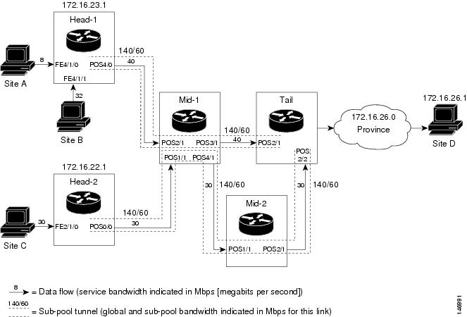
Example with Single Destination Prefix
Figure 2 illustrates a topology for guaranteed bandwidth services whose destination is specified by a single prefix, either Site D (like a voice gateway, here bearing prefix 172.16.26.1) or a subnet (like the location of a web farm, here called "Province" and bearing prefix 172.16.26.0). Three services are offered:
•
•
•
Figure 2 Sample Topology for Guaranteed Bandwidth Services to a Single Destination Prefix
These three services run through two sub-pool tunnels:
•
•
Both tunnels use the same tail router, though they have different heads. (In Figure 2, one midpoint router is shared by both tunnels. In the real world there could of course be many more midpoints.)
All POS interfaces in this example are OC3, whose capacity is 155 Mbps.
Configuring Tunnel Head-1
First we recapitulate commands that establish two bandwidth pools and a sub-pool tunnel (as presented earlier in this Configuration Examples section). Then we present the QoS commands that guarantee end-to-end service on the subpool tunnel. (With the 7500 router, Modular QoS CLI is used.)
Configuring the Pools and Tunnel
At the device level:
router-1(config)# ip cef distributedrouter-1(config)# mpls traffic-eng tunnels[now one uses either the IS-IS commands on the left or the OSPF commands on the right]
:
[now one resumes the common command set]:
router-1(config-router)# mpls traffic-eng router-id Loopback0router-1(config-router)# exitCreate a virtual interface:
router-1(config)# interface Loopback0router-1(config-if)# ip address 172.16.23.1 255.255.255.255router-1(config-if)# no ip directed-broadcastrouter-1(config-if)# exitAt the outgoing physical interface:
router-1(config)# interface pos4/0router-1(config-if)# ip address 10.1.1.1 255.0.0.0router-1(config-if)# mpls traffic-eng tunnelsrouter-1(config-if)# ip rsvp bandwidth 140000 140000 sub-pool 60000[and if using IS-IS instead of OSPF]:router-1(config-if)# ip router isis[and in all cases}:router-1(config-if)# exitAt the tunnel interface:
router-1(config)# interface Tunnel1router-1(config-if)# bandwidth 110000router-1(config-if)# ip unnumbered Loopback0router-1(config-if)# tunnel destination 172.16.27.1router-1(config-if)# tunnel mode mpls traffic-engrouter-1(config-if)# tunnel mpls traffic-eng priority 0 0router-1(config-if)# tunnel mpls traffic-eng bandwidth sub-pool 40000router-1(config-if)# tunnel mpls traffic-eng path-option 1 dynamicTo ensure that packets destined to host 172.16.26.1 and subnet 172.16.26.0 are sent into the sub-pool tunnel, we create a static route. At the device level:
router-1(config)# ip route 172.16.26.1 255.255.255.0 Tunnel1router-1(config)# exitAnd in order to make sure that the Interior Gateway Protocol (IGP) will not send any other traffic down this tunnel, we disable autoroute announce:
router-1(config)# no tunnel mpls traffic-eng autoroute announceFor Service from Site A to Site D
At the inbound physical interface (FE4/1/0):
1.
class-map match-all sla-1-classmatch access-group 1002.
access-list 100 permit ip any host 172.16.26.13.
a.
- a rate of 8 million bits per second
- a normal burst of 1 million bytes
- a maximum burst of 2 million bytes
b.
c.
d.
policy-map sla-1-input-policyclass sla-1-classpolice 8000000 1000000 2000000 conform-action set-mpls-exp-transmit 5 \ exceed-action dropclass class-defaultset-mpls-exp-transmit 04.
interface FastEthernet4/1/0service-policy input sla-1-input-policyFor Service from Site B to Subnet "Province"
At the inbound physical interface (FE4/1/1):
1.
class-map match-all sla-2-classmatch access-group 1202.
access-list 120 permit ip any 172.16.26.0 0.0.0.2553.
a.
- a rate of 32 million bits per second
- a normal burst of 1 million bytes
- a maximum burst of 2 million bytes
b.
c.
d.
policy-map sla-2-input-policyclass sla-2-classpolice 32000000 1000000 2000000 conform-action set-mpls-exp-transmit 5 \ exceed-action dropclass class-defaultset-mpls-exp-transmit 04.
interface FastEthernet4/1/1service-policy input sla-2-input-policyFor Both Services
The outbound interface (POS4/0) is configured as follows:
1.
class-map match-all exp-5-trafficmatch mpls experimental 52.
policy-map output-interface-policyclass exp-5-trafficpriority 323.
interface POS4/0service-policy output output-interface-policyThe result of the above configuration lines is that packets entering the Head-1 router via interface FE4/1/0 destined to host 172.16.26.1, or entering the router via interface FE4/1/1 destined to subnet 172.16.26.0, will have their MPLS experimental bit set to 5. We assume that no other packets entering the router (on any interface) are using this value. (If this cannot be assumed, an additional configuration must be added to mark all such packets to another experimental value.) Packets marked with experimental bit 5, when exiting the router via interface POS4/0, will be placed into the priority queue.
Note
Configuring Tunnel Head-2
First we recapitulate commands that establish two bandwidth pools and a sub-pool tunnel (as presented earlier in this Configuration Examples section). Then we present the QoS commands that guarantee end-to-end service on the sub-pool tunnel.
.Configuring the Pools and Tunnel
At the device level:
router-2(config)# ip cef distributedrouter-2(config)# mpls traffic-eng tunnels[now one uses either the IS-IS commands on the left or the OSPF commands on the right]
:
[now one resumes the common command set]:
router-2(config-router)# mpls traffic-eng router-id Loopback0router-2(config-router)# exitCreate a virtual interface:
router-2(config)# interface Loopback0router-2(config-if)# ip address 172.16.22.1 255.255.255.255router-2(config-if)# no ip directed broadcastrouter-2(config-if)# exitAt the outgoing physical interface:
router-2(config)# interface pos0/0router-2(config-if)# ip address 192.168.11.1 255.0.0.0router-2(config-if)# mpls traffic-eng tunnelsrouter-2(config-if)# ip rsvp bandwidth 140000 140000 sub-pool 60000[and if using IS-IS instead of OSPF]:router-2(config-if)# ip router isis[and in all cases]:router-2(config-if)# exitAt the tunnel interface:
router-2(config)# interface Tunnel2router-2(config-if)# ip unnumbered Loopback0router-2(config-if)# tunnel destination 172.16.27.1router-2(config-if)# tunnel mode mpls traffic-engrouter-2(config-if)# tunnel mpls traffic-eng priority 0 0router-2(config-if)# tunnel mpls traffic-eng bandwidth sub-pool 30000router-2(config-if)# tunnel mpls traffic-eng path-option 1 dynamicrouter-2(config-if)# exitAnd to ensure that packets destined to subnet 172.16.26.0 are sent into the sub-pool tunnel, we create a static route, at the device level:
router-2(config)# ip route 172.16.26.0 255.255.255.0 Tunnel2router-2(config)# exitFinally, in order to make sure that the Interior Gateway Protocol (IGP) will not send any other traffic down this tunnel, we disable autoroute announce:
router-2(config)# no tunnel mpls traffic-eng autoroute announceFor Service from Site C to Subnet "Province"
At the inbound physical interface (FE2/1/0):
1.
class-map match-all sla-3-classmatch access-group 1302.
access-list 130 permit ip any 172.16.26.0 0.0.0.2553.
a.
- a rate of 30 million bits per second
- a normal burst of 1 million bytes
- a maximum burst of 2 million bytes
b.
c.
d.
policy-map sla-3-input-policyclass sla-3-classpolice 30000000 1000000 2000000 conform-action set-mpls-exp-transmit 5 \ exceed-action dropclass class-defaultset-mpls-exp-transmit 04.
interface FastEthernet2/1/0service-policy input sla-3-input-policyThe outbound interface POS0/0 is configured as follows:
1.
class-map match-all exp-5-trafficmatch mpls experimental 52.
policy-map output-interface-policyclass exp-5-trafficpriority 323.
interface POS0/0service-policy output output-interface-policyAs a result of all the above configuration lines, packets entering theHead-2 router via interface FE2/1/0 and destined for subnet 172.16.26.0 have their IP precedence field set to 5. It is assumed that no other packets entering this router (on any interface) are using this precedence. (If this cannot be assumed, an additional configuration must be added to mark all such packets with another precedence value.) When exiting this router via interface POS0/0, packets marked with precedence 5 are placed in the priority queue.
Note
Tunnel Midpoint Configuration [Mid-1]
All four interfaces on the midpoint router are configured identically to the outbound interface of the head router (except, of course, for the IDs of the individual interfaces):
Configuring the Pools and Tunnels
At the device level:
router-3(config)# ip cef distributedrouter-3(config)# mpls traffic-eng tunnels[now one uses either the IS-IS commands on the left or the OSPF commands on the right]
:
[now one resumes the common command set]:
router-3(config-router)# mpls traffic-eng router-id Loopback0router-3(config-router)# exitCreate a virtual interface:
router-3(config)# interface Loopback0router-3(config-if)# ip address 172.16.24.1 255.255.255.255router-3(config-if)# exitAt the physical interface level (ingress):
router-3(config)# interface pos2/1router-3(config-if)# ip address 10.1.1.2 255.0.0.0router-3(config-if)# mpls traffic-eng tunnelsrouter-3(config-if)# ip rsvp bandwidth 140000 140000 sub-pool 60000[and if using IS-IS instead of OSPF]:router-3(config-if)# ip router isis[and in all cases]:router-3(config-if)# exitrouter-3(config)# interface pos1/1router-3(config-if)# ip address 192.168.11.2 255.0.0.0router-3(config-if)# mpls traffic-eng tunnelsrouter-3(config-if)# ip rsvp bandwidth 140000 140000 sub-pool 60000[and if using IS-IS instead of OSPF]:router-3(config-if)# ip router isis[and in all cases]:router-3(config-if)# exitAt the physical interface level (egress):
router-3(config)# interface pos3/1router-3(config-if)# ip address 192.168.12.1 255.0.0.0router-3(config-if)# mpls traffic-eng tunnelsrouter-3(config-if)# ip rsvp bandwidth 140000 140000 sub-pool 60000[and if using IS-IS instead of OSPF]:router-3(config-if)# ip router isis[and in all cases]:router-3(config-if)# exitrouter-3(config)# interface pos4/1router-3(config-if)# ip address 192.168.13.1 255.0.0.0router-3(config-if)# mpls traffic-eng tunnelsrouter-3(config-if)# ip rsvp bandwidth 140000 140000 sub-pool 60000[and if using IS-IS instead of OSPF]:router-3(config-if)# ip router isis[and in all cases]:router-3(config-if)# exitTunnel Midpoint Configuration [Mid-2]
Both interfaces on the midpoint router are configured identically to the outbound interface of the head router (except, of course, for the IDs of the individual interfaces):
Configuring the Pools and Tunnel
At the device level:
router-5(config)# ip cef distributedrouter-5(config)# mpls traffic-eng tunnels[now one uses either the IS-IS commands on the left or the OSPF commands on the right]
:
[now one resumes the common command set]:
router-5(config-router)# mpls traffic-eng router-id Loopback0router-5(config-router)# exitCreate a virtual interface:
router-5(config)# interface Loopback0router-5(config-if)# ip address 172.16.25.1 255.255.255.255router-5(config-if)# exitAt the physical interface level (ingress):
router-5(config)# interface pos1/1router-5(config-if)# ip address 192.168.13.2 255.0.0.0router-5(config-if)# mpls traffic-eng tunnelsrouter-5(config-if)# ip rsvp bandwidth 140000 140000 sub-pool 60000[and if using IS-IS instead of OSPF]:router-5(config-if)# ip router isis[and in all cases]:router-5(config-if)# exitAt the physical interface level (egress):
router-5(config)# interface pos2/1router-5(config-if)# ip address 192.168.14.1 255.0.0.0router-5(config-if)# mpls traffic-eng tunnelsrouter-5(config-if)# ip rsvp bandwidth 140000 140000 sub-pool 60000[and if using IS-IS instead of OSPF]:router-5(config-if)# ip router isis[and in all cases]:router-5(config-if)# exitTunnel Tail Configuration
The inbound interfaces on the tail router are configured identically to the inbound interfaces of the midpoint routers (except, of course, for the ID of each particular interface):
Configuring the Pools and Tunnels
At the device level:
router-4(config)# ip cef distributedrouter-4(config)# mpls traffic-eng tunnels[now one uses either the IS-IS commands on the left or the OSPF commands on the right]
:
[now one resumes the common command set]:
router-4(config-router)# mpls traffic-eng router-id Loopback0router-4(config-router)# exitCreate a virtual interface:
router-4(config)# interface Loopback0router-4(config-if)# ip address 172.16.27.1 255.255.255.255router-4(config-if)# exitAt the physical interface (ingress):
router-4(config)# interface pos2/1router-4(config-if)# ip address 192.168.12.2 255.0.0.0router-4(config-if)# mpls traffic-eng tunnelsrouter-4(config-if)# ip rsvp bandwidth 140000 140000 sub-pool 60000[and if using IS-IS instead of OSPF]:router-4(config-if)# ip router isis[and in all cases]:router-4(config-if)# exitrouter-4(config)# interface pos2/2router-4(config-if)# ip address 192.168.14.2 255.0.0.0router-4(config-if)# mpls traffic-eng tunnelsrouter-4(config-if)# ip rsvp bandwidth 140000 140000 sub-pool 60000[and if using IS-IS instead of OSPF]:router-4(config-if)# ip router isis[and in all cases]:router-4(config-if)# exitBecause the tunnel ends on the tail (does not include any outbound interfaces of the tail router), no outbound QoS configuration is used.
Example with Many Destination Prefixes
Figure 3 illustrates a topology for guaranteed bandwidth services whose destinations are a set of prefixes. Those prefixes usually share some common properties such as belonging to the same Autonomous System (AS) or transiting through the same AS. Although the individual prefixes may change dynamically because of route flaps in the downstream autonomous systems, the properties the prefixes share will not change. Policies addressing the destination prefix set are enforced through Border Gateway Protocol (BGP), which is described in the following documents:
•
•
•
•
In this example, three guaranteed bandwidth services are offered, each coming through a 7500 or a 12000 edge device:
•
•
•
Figure 3 Sample Topology for Guaranteed Bandwidth Service to Many Destination Prefixes
The applicability of guaranteed bandwidth service is not limited to the three types of multiple destination scenarios described above. There is not room in this document to present all possible scenarios. These three were chosen as representative of the wide range of possible deployments.
The guaranteed bandwidth services run through two sub-pool tunnels:
•
•
In addition, a global pool tunnel has been configured from each head end, to carry best-effort traffic to the same destinations. All four tunnels use the same tail router, even though they have different heads and differ in their passage through the midpoints. (Of course in the real world there would be many more midpoints than just the two shown here.)
All POS interfaces in this example are OC3, whose capacity is 155 Mbps.
Configuring a multi-destination guaranteed bandwidth service involves:
a.
b.
c.
d.
All of these tasks are included in the following example.
Configuration of Tunnel Head-1
First we recapitulate commands that establish a sub-pool tunnel (commands presented earlier on page 8) and now we also configure a global pool tunnel. Additionally, we present QoS and BGP commands that guarantee end-to-end service on the sub-pool tunnel. (With the 7500(VIP) router, Modular QoS CLI is used).
Configuring the Pools and Tunnels
At the device level:
router-1(config)# ip cef distributedrouter-1(config)# mpls traffic-eng tunnels[now one uses either the IS-IS commands on the left or the OSPF commands on the right]
:
[now one resumes the common command set]:
router-1(config-router)# mpls traffic-eng router-id Loopback0router-1(config-router)# exitCreate a virtual interface:
router-1(config)# interface Loopback0router-1(config-if)# ip address 172.16.23.1 255.255.255.255router-1(config-if)# exitAt the outgoing physical interface:
router-1(config)# interface pos4/0router-1(config-if)# ip address 10.1.1.1 255.0.0.0router-1(config-if)# mpls traffic-eng tunnelsrouter-1(config-if)# ip rsvp bandwidth 140000 140000 sub-pool 60000[and if using IS-IS instead of OSPF]:router-1(config-if)# ip router isis[and in all cases]:router-1(config-if)# exitAt one tunnel interface, create a sub-pool tunnel:
router-1(config)# interface Tunnel1router-1(config-if)# ip unnumbered Loopback0router-1(config-if)# tunnel destination 172.16.27.1router-1(config-if)# tunnel mode mpls traffic-engrouter-1(config-if)# tunnel mpls traffic-eng priority 0 0router-1(config-if)# tunnel mpls traffic-eng bandwidth sub-pool 40000router-1(config-if)# tunnel mpls traffic-eng path-option 1 explicit name gbs-path1router-1(config-if)# exitand at a second tunnel interface, create a global pool tunnel:
router-1(config)# interface Tunnel2router-1(config-if)# ip unnumbered Loopback0router-1(config-if)# tunnel destination 172.16.27.1router-1(config-if)# tunnel mode mpls traffic-engrouter-1(config-if)# tunnel mpls traffic-eng priority 0 0router-1(config-if)# tunnel mpls traffic-eng bandwidth 80000router-1(config-if)# tunnel mpls traffic-eng path-option 1 explicit name \ best-effort-path1router-1(config-if)# exitIn this example explicit paths are used instead of dynamic, to ensure that best-effort traffic and guaranteed bandwidth traffic will travel along different paths.
At the device level:
router-1(config)# ip explicit-path name gbs-path1router-1(config-ip-expl-path)# next-address 172.16.24.1router-1(config-ip-expl-path)# next-address 172.16.27.1router-1(config-ip-expl-path)# exitrouter-1(config)# ip explicit-path name best-effort-path1router-1(config-ip-expl-path)# next-address 172.16.24.1router-1(config-ip-expl-path)# next-address 172.16.25.1router-1(config-ip-expl-path)# next-address 172.16.27.1router-1(config-ip-expl-path)# exitNote that autoroute is not used, as that could cause the Interior Gateway Protocol (IGP) to send other traffic down these tunnels.
Configuring DiffServ QoS
At the inbound physical interface (in Figure 3 this is FE4/1/0), packets received are rate-limited to:
a.
b.
c.
Packets that are mapped to qos-group 6 and that conform to the rate-limit are marked with experimental value 5 and the BGP destination community string, and are forwarded; packets that do not conform (exceed action) are dropped:
router-1(config)# interface FastEthernet4/1/0router-1(config-if)# rate-limit input qos-group 6 30000000 1000000 2000000 \ conform-action set-mpls-exp-transmit 5 exceed-action droprouter-1(config-if)# bgp-policy destination ip-qos-maprouter-1(config-if)# exitAt the device level create a class of traffic called "exp5-class" that has MPLS experimental bit set to 5:
router-1(config)# class-map match-all exp5-classrouter-1(config-cmap)# match mpls experimental 5router-1(config-cmap)# exitCreate a policy that creates a priority queue for "exp5-class":
router-1(config)# policy-map core-out-policyrouter-1(config-pmap)# class exp5-classrouter-1(config-pmap-c)# priority 100000router-1(config-pmap-c)# exitrouter-1(config-pmap)# class class-defaultrouter-1(config-pmap-c)# bandwidth 55000router-1(config-pmap-c)# exitrouter-1(config-pmap)# exitThe policy is applied to packets exiting the outbound interface POS4/0.
router-1(config)# interface POS4/0router-1(config-if)# service-policy output core-out-policyConfiguring QoS Policy Propagation via BGP
For All GB Services
Create a table map under BGP to map (tie) the prefixes to a qos-group. At the device level:
router-1(config)# ip bgp-community new-formatrouter-1(config)# router bgp 2router-1(config-router)# no synchronizationrouter-1(config-router)# table-map set-qos-grouprouter-1(config-router)# bgp log-neighbor-changesrouter-1(config-router)# neighbor 172.16.27.1 remote-as 2router-1(config-router)# neighbor 172.16.27.1 update-source Loopback0router-1(config-router)# no auto-summaryrouter-1(config-router)# exitFor GB Service Destined to AS5
Create a distinct route map for this service. This includes setting the next-hop of packets matching 172.16.29.1 so they will be mapped onto Tunnel #1 (the guaranteed bandwidth service tunnel). At the device level:
router-1(config)# route-map set-qos-group permit 10router-1(config-route-map)# match as-path 100router-1(config-route-map)# set ip qos-group 6router-1(config-route-map)# set ip next-hop 172.16.29.1router-1(config-route-map)# exitrouter-1(config)# ip as-path access-list 100 permit ^5$For GB Service Transiting through AS5
Create a distinct route map for this service. (Its traffic will go to AS6 and AS7).
At the device level:
router-1(config)# route-map set-qos-group permit 10router-1(config-route-map)# match as-path 101router-1(config-route-map)# set ip qos-group 6router-1(config-route-map)# set ip next-hop 172.16.29.1router-1(config-route-map)# exitrouter-1(config)# ip as-path access-list 101 permit _5_For GB Service Destined to Community 100:1
Create a distinct route map for all traffic destined to prefixes that have community value 100:1. This traffic will go to AS3, AS5, and AS8.
At the device level:
router-1(config)# route-map set-qos-group permit 10router-1(config-route-map)# match community 20router-1(config-route-map)# set ip qos-group 6router-1(config-route-map)# set ip next-hop 172.16.29.1router-1(config-route-map)# exitrouter-1(config)# ip community-list 20 permit 100:1Mapping Traffic onto the Tunnels
Map all guaranteed bandwidth traffic onto Tunnel #1:
router-1(config)# ip route 172.16.29.1 255.255.255.255 Tunnel1Map all best-effort traffic onto Tunnel #2:
router-1(config)# ip route 172.16.30.1 255.255.255.255 Tunnel2Configuration of Tunnel Head-2
As with the Head-1 device and interfaces, the following Head-2 configuration first presents commands that establish a sub-pool tunnel (commands presented earlier on page 8) and then also configures a global pool tunnel. After that it presents QoS and BGP commands that guarantee end-to-end service on the sub-pool tunnel. (Because this is a 7500 (VIP) router, Modular QoS CLI is used).
Configuring the Pools and Tunnels
At the device level:
router-2(config)# ip cef distributedrouter-2(config)# mpls traffic-eng tunnels[now one uses either the IS-IS commands on the left or the OSPF commands on the right]
:
[now one resumes the common command set]:
router-2(config-router)# mpls traffic-eng router-id Loopback0router-2(config-router)# exitCreate a virtual interface:
router-2(config)# interface Loopback0router-2(config-if)# ip address 172.16.22.1 255.255.255.255router-2(config-if)# exitAt the outgoing physical interface:
router-2(config)# interface pos0/0router-2(config-if)# ip address 192.168.11.1 255.0.0.0router-2(config-if)# mpls traffic-eng tunnelsrouter-2(config-if)# ip rsvp bandwidth 140000 140000 sub-pool 60000[and if using IS-IS instead of OSPF]:router-2(config-if)# ip router isis[and in all cases]:router-2(config-if)# exitAt one tunnel interface, create a sub-pool tunnel:
router-2(config)# interface Tunnel3router-2(config-if)# ip unnumbered Loopback0router-2(config-if)# tunnel destination 172.16.27.1router-2(config-if)# tunnel mode mpls traffic-engrouter-2(config-if)# tunnel mpls traffic-eng priority 0 0router-2(config-if)# tunnel mpls traffic-eng bandwidth sub-pool 30000router-2(config-if)# tunnel mpls traffic-eng path-option 1 explicit name gbs-path2router-2(config-if)# exitand at a second tunnel interface, create a global pool tunnel:
router-2(config)# interface Tunnel4router-2(config-if)# ip unnumbered Loopback0router-2(config-if)# tunnel destination 172.16.27.1router-2(config-if)# tunnel mode mpls traffic-engrouter-2(config-if)# tunnel mpls traffic-eng priority 0 0router-2(config-if)# tunnel mpls traffic-eng bandwidth 70000router-2(config-if)# tunnel mpls traffic-eng path-option 1 explicit name \ best-effort-path2router-2(config-if)# exitIn this example explicit paths are used instead of dynamic, to ensure that best-effort traffic and guaranteed bandwidth traffic will travel along different paths.
At the device level:
router-2(config)# ip explicit-path name gbs-path2router-2(config-ip-expl-path)# next-address 172.16.24.1router-2(config-ip-expl-path)# next-address 172.16.27.1router-2(config-ip-expl-path)# exitrouter-2(config)# ip explicit-path name best-effort-path2router-2(config-ip-expl-path)# next-address 172.16.24.1router-2(config-ip-expl-path)# next-address 172.16.25.1router-2(config-ip-expl-path)# next-address 172.16.27.1router-2(config-ip-expl-path)# exitNote that autoroute is not used, as that could cause the Interior Gateway Protocol (IGP) to send other traffic down these tunnels.
Configuring DiffServ QoS
At the inbound physical interface (in Figure 3 this is FE2/1), packets received are rate-limited to:
a.
b.
c.
Packets that are mapped to qos-group 6 and that conform to the rate-limit are marked with experimental value 5 and the BGP destination community string, and are forwarded; packets that do not conform (exceed action) are dropped:
router-2(config)# interface FastEthernet2/1router-2(config-if)# rate-limit input qos-group 6 30000000 1000000 2000000 \ conform-action set-mpls-exp-transmit 5 exceed-action droprouter-2(config-if)# bgp-policy destination ip-qos-maprouter-1(config-if)# exitAt the device level create a class of traffic called "exp5-class" that has MPLS experimental bit set to 5:
router-2(config)# class-map match-all exp5-classrouter-2(config-cmap)# match mpls experimental 5router-2(config-cmap)# exitCreate a policy that creates a priority queue for "exp5-class":
router-2(config)# policy-map core-out-policyrouter-2(config-pmap)# class exp5-classrouter-2(config-pmap-c)# priority 100000router-2(config-pmap-c)# exitrouter-2(config-pmap)# class class-defaultrouter-2(config-pmap-c)# bandwidth 55000router-2(config-pmap-c)# exitrouter-2(config-pmap)# exitThe policy is applied to packets exiting interface POS0/0:
interface POS0/0service-policy output core-out-policyAs a result of all the above configuration lines, packets entering the Head-2 router via interface FE2/1 and destined for AS5, BGP community 100:1, or transiting AS5 will have their experimental field set to 5. It is assumed that no other packets entering this router (on any interface) are using this exp bit value. (If this cannot be assumed, an additional configuration must be added to mark all such packets with another experimental value.) When exiting this router via interface POS0/0, packets marked with experimental value 5 are placed into the priority queue.
Note
Configuring QoS Policy Propagation via BGP
For All GB Services
Create a table map under BGP to map (tie) the prefixes to a qos-group. At the device level:
router-2(config)# ip bgp-community new-formatrouter-2(config)# router bgp 2router-2(config-router)# no synchronizationrouter-2(config-router)# table-map set-qos-grouprouter-2(config-router)# bgp log-neighbor-changesrouter-2(config-router)# neighbor 172.16.27.1 remote-as 2router-2(config-router)# neighbor 172.16.27.1 update-source Loopback0router-2(config-router)# no auto-summaryrouter-2(config-router)# exitFor GB Service Destined to AS5
Create a distinct route map for this service. This includes setting the next-hop of packets matching 29.1.1.1 so they will be mapped onto Tunnel #3 (the guaranteed bandwidth service tunnel). At the device level:
router-2(config)# route-map set-qos-group permit 10router-2(config-route-map)# match as-path 100router-2(config-route-map)# set ip qos-group 6router-2(config-route-map)# set ip next-hop 172.16.29.1router-2(config-route-map)# exitrouter-2(config)# ip as-path access-list 100 permit ^5$For GB Service Transiting through AS5
Create a distinct route map for this service. (Its traffic will go to AS6 and AS7).
At the device level:
router-2(config)# route-map set-qos-group permit 10router-2(config-route-map)# match as-path 101router-2(config-route-map)# set ip qos-group 6router-2(config-route-map)# set ip next-hop 172.16.29.1router-2(config-route-map)# exitrouter-2(config)# ip as-path access-list 101 permit _5_For GB Service Destined to Community 100:1
Create a distinct route map for all traffic destined to prefixes that have community value 100:1. This traffic will go to AS3, AS5, and AS8.
At the device level:
router-2(config)# route-map set-qos-group permit 10router-2(config-route-map)# match community 20router-2(config-route-map)# set ip qos-group 6router-2(config-route-map)# set ip next-hop 172.16.29.1router-2(config-route-map)# exitrouter-2(config)# ip community-list 20 permit 100:1Mapping the Traffic onto the Tunnels
Map all guaranteed bandwidth traffic onto Tunnel #3:
router-2(config)# ip route 172.16.29.1 255.255.255.255 Tunnel3Map all best-effort traffic onto Tunnel #4:
router-2(config)# ip route 172.16.30.1 255.255.255.255 Tunnel4Tunnel Midpoint Configuration [Mid-1]
All four interfaces on the midpoint router are configured very much like the outbound interface of the head router. The strategy is to have all mid-point routers in this Autonomous System ready to carry future as well as presently configured sub-pool and global pool tunnels.
Configuring the Pools and Tunnels
At the device level:
router-3(config)# ip cef distributedrouter-3(config)# mpls traffic-eng tunnels[now one uses either the IS-IS commands on the left or the OSPF commands on the right]
:
[now one resumes the common command set]:
router-3(config-router)# mpls traffic-eng router-id Loopback0router-3(config-router)# exitCreate a virtual interface:
router-3(config)# interface Loopback0router-3(config-if)# ip address 172.16.24.1 255.255.255.255router-3(config-if)# exitAt the physical interface level (ingress):
router-3(config)# interface pos2/1router-3(config-if)# ip address 10.1.1.2 255.0.0.0router-3(config-if)# mpls traffic-eng tunnelsrouter-3(config-if)# ip rsvp bandwidth 140000 140000 sub-pool 70000[and if using IS-IS instead of OSPF]:router-3(config-if)# ip router isis[and in all cases]:router-3(config-if)# exitrouter-3(config)# interface pos1/1router-3(config-if)# ip address 192.168.11.2 255.0.0.0router-3(config-if)# mpls traffic-eng tunnelsrouter-3(config-if)# ip rsvp bandwidth 140000 140000 sub-pool 70000[and if using IS-IS instead of OSPF]:router-3(config-if)# ip router isis[and in all cases]:router-3(config-if)# exitAt the physical interface level (egress), through which two sub-pool tunnels currently exit:
router-3(config)# interface pos3/1router-3(config-if)# ip address 192.168.12.1 255.0.0.0router-3(config-if)# mpls traffic-eng tunnelsrouter-3(config-if)# ip rsvp bandwidth 140000 140000 sub-pool 70000[and if using IS-IS instead of OSPF]:router-3(config-if)# ip router isis[and in all cases]:router-3(config-if)# exitAt the physical interface level (egress), through which two global pool tunnels currently exit:
router-3(config)# interface pos4/1router-3(config-if)# ip address 192.168.13.1 255.0.0.0router-3(config-if)# mpls traffic-eng tunnelsrouter-3(config-if)# ip rsvp bandwidth 140000 140000 sub-pool 70000[and if using IS-IS instead of OSPF]:router-3(config-if)# ip router isis[and in all cases]:router-3(config-if)# exitTunnel Midpoint Configuration [Mid-2]
Both interfaces on this midpoint router are configured like the outbound interfaces of the Mid-1 router.
Configuring the Pools and Tunnels
At the device level:
router-5(config)# ip cef distributedrouter-5(config)# mpls traffic-eng tunnels[now one uses either the IS-IS commands on the left or the OSPF commands on the right]
:
[now one resumes the common command set]:
router-5(config-router)# mpls traffic-eng router-id Loopback0router-5(config-router)# exitCreate a virtual interface:
router-5(config)# interface Loopback0router-5(config-if)# ip address 172.16.25.1 255.255.255.255router-5(config-if)# exitAt the physical interface level (ingress):
router-5(config)# interface pos1/1router-5(config-if)# ip address 192.168.13.2 255.0.0.0router-5(config-if)# mpls traffic-eng tunnelsrouter-5(config-if)# ip rsvp bandwidth 140000 140000 sub-pool 70000[and if using IS-IS instead of OSPF]:router-5(config-if)# ip router isis[and in all cases]:router-5(config-if)# exitAt the physical interface level (egress):
router-5(config)# interface pos2/1router-5(config-if)# ip address 192.168.14.1 255.0.0.0router-5(config-if)# mpls traffic-eng tunnelsrouter-5(config-if)# ip rsvp bandwidth 140000 140000 sub-pool 70000[and if using IS-IS instead of OSPF]:router-5(config-if)# ip router isis[and in all cases]:router-5(config-if)# exitTunnel Tail Configuration
The inbound interfaces on the tail router are configured much like the outbound interfaces of the midpoint routers:
Configuring the Pools and Tunnels
At the device level:
router-4(config)# ip cef distributedrouter-4(config)# mpls traffic-eng tunnels[now one uses either the IS-IS commands on the left or the OSPF commands on the right. In the case of OSPF, one must advertise two new loopback interfaces—172.16.29.1 and 172.16.30.1 in our example—which are defined in the QoS Policy Propagation section, further along on this page]
:
[now one resumes the common command set, taking care to include the two additional loopback interfaces]:
router-4(config-router)# mpls traffic-eng router-id Loopback0router-4(config-router)# mpls traffic-eng router-id Loopback1router-4(config-router)# mpls traffic-eng router-id Loopback2router-4(config-router)# exitCreate a virtual interface:
router-4(config)# interface Loopback0router-4(config-if)# ip address 172.16.27.1 255.255.255.255router-4(config-if)# exitAt the physical interface (ingress):
router-4(config)# interface pos2/1router-4(config-if)# ip address 192.168.12.2 255.0.0.0router-4(config-if)# mpls traffic-eng tunnelsrouter-4(config-if)# ip rsvp bandwidth 140000 140000 sub-pool 70000[and if using IS-IS instead of OSPF]:router-4(config-if)# ip router isis[and in all cases]:router-4(config-if)# exitrouter-4(config)# interface pos2/2router-4(config-if)# ip address 192.168.14.2 255.0.0.0router-4(config-if)# mpls traffic-eng tunnelsrouter-4(config-if)# ip rsvp bandwidth 140000 140000 sub-pool 70000[and if using IS-IS instead of OSPF]:router-4(config-if)# ip router isis[and in all cases]:router-4(config-if)# exitConfiguring QoS Policy Propagation
On the tail device, one must configure a separate virtual loopback IP address for each class-of-service terminating here. The headend routers need these addresses to map traffic into the proper tunnels. In the current example, four tunnels terminate on the same tail device but they represent only two service classes, so only two additional loopback addresses are needed:
Create two virtual interfaces:
router-4(config)# interface Loopback1router-4(config-if)# ip address 172.16.29.1 255.255.255.255[and if using IS-IS instead of OSPF]:router-4(config-if)# ip router isis[and in all cases]:router-4(config-if)# exitrouter-4(config)# interface Loopback2router-4(config-if)# ip address 172.16.30.1 255.255.255.255[and if using IS-IS instead of OSPF]:router-4(config-if)# ip router isis[and in all cases]:router-4(config-if)# exitAt the device level, configure BGP to send the community to each tunnel head:
router-4(config)# ip bgp-community new-formatrouter-4(config)# router bgp 2router-4(config-router)# neighbor 172.16.23.1 send-communityrouter-4(config-router)# neighbor 172.16.22.1 send-communityrouter-4(config-router)# exitAdditional References
The following sections provide references related to MPLS Traffic Engineering—DiffServ Aware.
Related Documents
Configuring OSPF
"Configuring OSPF" section in the Cisco IOS IP Routing Protocols Configuration Guide, Release 12.4
OSPF commands
"OSPF Commands" section in the Cisco IOS IP Routing Protocols Command Reference, Release 12.4T
Configuring integrated IS-IS
"Configuring Integrated IS-IS" section in the Cisco IOS IP Routing Protocols Configuration Guide, Release 12.4
Integrated IS-IS commands
"Integrated IS-IS Commands" section in the Cisco IOS IP Routing Protocols Command Reference, Release 12.4T
Configuring RSVP
"Configuring RSVP" section in the Cisco IOS Quality of Service Solutions Configuration Guide, Release 12.4
IP RSVP commands
Cisco IOS Quality of Service Solutions Command Reference, Release 12.4T
Configuring QoS
Cisco IOS Quality of Service Solutions Configuration Guide, Release 12.4
QoS commands
Cisco IOS Quality of Service Solutions Command Reference, Release 12.4T
MPLS traffic engineering
•
•
•
Standards
MIBs
None
To locate and download MIBs for selected platforms, Cisco IOS releases, and feature sets, use Cisco MIB Locator found at the following URL:
RFCs
Technical Assistance
Command Reference
This section documents modified commands only.
•
•
•
•
•
•
•
•
•
•
•
•
•
•
•
•
•
•
•
•
•
•
•
•
•
•
•
•
•
debug mpls traffic-eng link-management preemption
To print information about traffic engineering label-switched path (LSP) preemption, use the debug mpls traffic-eng link-management preemption command in privileged EXEC mode. To disable debugging output, use the no form of this command.
debug mpls traffic-eng link-management preemption [detail]
no debug mpls traffic-eng link-management preemption [detail]
Syntax Description
Defaults
No default behavior or values
Command Modes
Privileged EXEC
Command History
12.1(3)T
This command was introduced.
12.2(28)SB
This command was integrated into Cisco IOS Release 12.2(28)SB.
Examples
In the following example, detailed debugging information is printed about traffic engineering LSP preemption:
Router# debug mpls traffic-eng link-management preemption detailTE-LM-BW:preempting Downstream bandwidth, 1000000, for tunnel 10.106.0.6 2_2TE-LM-BW:building preemption list to get bandwidth, 1000000, for tunnel 10.106.0.6 2_2 (priority 0)TE-LM-BW:added bandwidth, 3000000, from tunnel 10.106.0.6 1_2 (pri 1) to preemption listTE-LM-BW:preemption list build to get bw, 1000000, succeeded (3000000)TE-LM-BW:preempting bandwidth, 1000000, using plist with 1 tunnelsTE-LM-BW:tunnel 10.106.0.6 1_2:being preempted on AT0/0.2 by 10.106.0.6 2_2TE-LM-BW:preemption of Downstream bandwidth, 1000000, succeededinterface
To configure an interface type and enter interface configuration mode, use the interface command in global configuration mode.
Standard Syntax
interface type number [name-tag]
Analysis Module Network Module
interface analysis-module slot/unit
Content Engine Network Module
interface content-engine slot/unit
Cisco 830 Series
interface type [number]
Cisco 2600 Series
interface type slot/{port-adapter | port.subinterface-number}
Cisco 2600 Series on Voice Interfaces
interface type slot/voice-module-slot/voice-interface-slot
Cisco 3600 Series
interface type slot/{port | port.subinterface-number}
Cisco 3600 Series on Voice Interfaces
interface type slot/voice-module-slot/voice-interface-slot
Cisco 7100 Series
interface type slot/{port-adapter | port.subinterface-number}
Cisco 7200 Series and Cisco 7500 Series with a Packet over SONET Interface Processor
interface type slot/port
Cisco 7200 VXR Router Used as a Router Shelf in a Cisco AS5800 Universal Access Server
interface type router-shelf/slot/port
Cisco 7500 Series with Channelized T1 or E1
interface serial slot/port:channel-group
Cisco 7500 Series with Ports on VIP Cards
interface type slot/port-adapter/port
To configure a subinterface, use this form of the interface global configuration command.
Cisco 7200 Series
interface type slot/port.subinterface-number [multipoint | point-to-point]
Cisco 7500 Series
interface type slot/port-adapter.subinterface-number [multipoint | point-to-point]
Cisco 7500 Series with Ports on VIP Cards
interface type slot/port-adapter/port.subinterface-number [multipoint | point-to-point]
Cisco 12000 Series
interface type slot/{port-adapter | port.subinterface-number}
Shared Port Adapters
interface type slot/subslot/port[.subinterface-number]
Syntax Description
type
Type of interface to be configured. See Table 1.
number
Port, connector, or interface card number. On Cisco 830 series routers, number specifies the ethernet interface number. On Cisco 4700 series routers, specifies the network interface module (NIM) or network processor module (NPM) number. The numbers are assigned at the factory at the time of installation or when added to a system, and can be displayed with the show interfaces command.
name-tag
(Optional) Specifies the logic name to identify the server configuration so that multiple server configurations can be entered.
This optional argument is for use with the Redundant Link Manager (RLM) feature.
slot
Chassis slot number.
Refer to the appropriate hardware manual for slot information. For SIPs, refer to the platform-specific SPA hardware installation guide or the corresponding "Identifying Slots and Subslots for SIPs and SPAs" topic in the platform-specific SPA software configuration guide.
/voice-module-slot
Voice module slot number.
Refer to the "Cisco 3700 Series Routers Voice Interface Numbering" section of the "Understanding Interface Numbering and Cisco IOS Basics" chapter in the platform-specific SPA software configuration guide.
/voice-interface-slot
Voice interface slot number.
Refer to the "Cisco 3700 Series Routers Voice Interface Numbering" section of the "Understanding Interface Numbering and Cisco IOS Basics" chapter in the platform-specific SPA software configuration guide.
/subslot
Secondary slot number on a SIP where a SPA is installed.
Refer to the platform-specific SPA hardware installation guide and the corresponding "Specifying the Interface Address on a SPA" topic in the platform-specific SPA software configuration guide for subslot information.
/unit
Number of the daughter card on the network module. For analysis module and content engine (CE) network modules, always use 0.
/port
Port or interface number.
Refer to the appropriate hardware manual for port information. For SPAs, refer to the corresponding "Specifying the Interface Address on a SPA" topics in the platform-specific SPA software configuration guide.
router-shelf
Router shelf number in a Cisco AS5800 universal access server. Refer to the appropriate hardware manual for router shelf information.
:channel-group
Channel group number. Cisco 7500 series routers specify the channel group number in the range of 0 to 4 defined with the channel-group controller configuration command.
/port-adapter
Port adapter number. Refer to the appropriate hardware manual for information about port adapter compatibility.
.subinterface-number
Subinterface number in the range 1 to 4294967293. The number that precedes the period (.) must match the number to which this subinterface belongs.
multipoint | point-to-point
(Optional) Specifies a multipoint or point-to-point subinterface. There is no default.
Command Default
No interface types are configured.
Command Modes
Global configuration
Note
Command History
Usage Guidelines
This command does not have a no form.
Subinterfaces can be configured to support partially meshed Frame Relay networks. Refer to the "Configuring Serial Interfaces" chapter in the Cisco IOS Interface and Hardware Component Configuration Guide.
Table 1 displays the keywords that represent the types of interfaces that can be configured with the interface command. Replace the type argument with the appropriate keyword from the table.
Using the analysis-module Keyword
The analysis module interface is used to access the NAM console for the initial configuration. After the NAM IP parameters are configured, the analysis module interface is typically used only during NAM software upgrades and while troubleshooting if the NAM Traffic Analyzer is inaccessible.
Visible only to the Cisco IOS software on the router, the analysis module interface is an internal Fast Ethernet interface on the router that connects to the internal NAM interface. The analysis module interface is connected to the router's Peripheral Component Interconnect (PCI) backplane, and all configuration and management of the analysis module interface must be performed from the Cisco IOS CLI.
Using the group-async Keyword
Using the group-async keyword, you create a single asynchronous interface with which other interfaces are associated as members using the group-range command. This one-to-many configuration allows you to configure all associated member interfaces by entering one command on the group master interface, rather than entering this command on each individual interface. You can create multiple group masters on a device; however, each member interface can be associated only with one group.
Using the port-channel Keyword
The Fast EtherChannel feature allows multiple Fast Ethernet point-to-point links to be bundled into one logical link to provide bidirectional bandwidth of up to 800 Mbps. You can configure the port-channel interface as you would any Fast Ethernet interface.
After you create a port-channel interface, you assign Fast Ethernet interfaces (up to four) to it. For information on how to assign a Fast Ethernet interface to a port-channel interface, refer to the channel-group command in the interface configuration mode.
Caution
Fast Ethernet interfaces. Do not assign bridge groups on the physical Fast Ethernet interfaces
because doing so creates loops. Also, you must disable spanning tree.
Caution
ip route-cache distributed commands from the Fast Ethernet interfaces before enabling dCEF on
the port-channel interface. Clearing the route cache gives the port-channel interface proper control
of its physical Fast Ethernet links. When you enable CEF/dCEF globally, all interfaces that support CEF/dCEF are enabled. When CEF/dCEF is enabled on the port-channel interface, it is automatically enabled on each of the Fast Ethernet interfaces in the channel group. However, if you have
previously disabled CEF/dCEF on the Fast Ethernet interface, CEF/dCEF is not automatically
enabled. In this case, you must enable CEF/dCEF on the Fast Ethernet interface.
As you work with the port-channel keyword, consider the following points:
•
•
Using the vg-anylan Keyword
The 100VG-AnyLAN port adapter provides a single interface port that is compatible with and specified by IEEE 802.12. The 100VG-AnyLAN port adapter provides 100 Mbps over Category 3 or Category 5 unshielded twisted-pair (UTP) cable with RJ-45 terminators, and supports IEEE 802.3 Ethernet packets.
You configure the 100VG-AnyLAN port adapter as you would any Ethernet or Fast Ethernet interface. The 100VG-AnyLAN port adapter can be monitored with the IEEE 802.12 Interface MIB.
Examples
Serial Interface with PPP Encapsulation Example
The following example shows how to configure serial interface 0 with PPP encapsulation:
Router(config)# interface serial 0Router(config-if)# encapsulation pppLoopback Interface Example
The following example shows how to enable loopback mode and assigns an IP network address and network mask to the interface. The loopback interface established here will always appear to be up.
Router(config)# interface loopback 0Router(config-if)# ip address 10.108.1.1 255.255.255.0Ethernet Port on Ethernet Interface Processor on Cisco 7500 Series Router Example
The following example shows how to configure Ethernet port 4 on the Ethernet Interface Processor (EIP) in slot 2 on the Cisco 7500 series router:
Router(config)# interface ethernet 2/4Token Ring Interface Processor Example
The following example shows how to configure the Token Ring interface processor in slot 1 on port 0 of a Cisco 7500 series router:
Router(config)# interface tokenring 1/0Analysis Module Interface with NAM Router Example
The following example configures an analysis module interface when the NAM router is in router slot 1:
Router(config)# interface analysis-module 1/0Content Engine Network Module Interface Example
The following example configures an interface for a content engine network module in slot 1:
Router(config)# interface content-engine 1/0Ethernet Interface on Cisco 830 Router Example
The following example configures a new interface ethernet2 on the LAN or on the WAN side of the Cisco 830 Series router.
c837#conf terminalEnter configuration commands, one per line. End with CNTL/Z.c837(config)#interface ethernet 2Fast Ethernet Interface on Cisco 2600 Router Example
The following example shows how to configure Fast Ethernet interface 0 on a Cisco 2600 series router:
Router(config)# interface fastethernet0/0orRouter(config)# interface fastethernet0/0.1Fast Ethernet Interface on Cisco 3600 Router Example
The following example shows how to configure Fast Ethernet interface 0 on a Cisco 3600 series router:
Router(config)# interface fastethernet0/0orRouter(config)# interface fastethernet0/0.1Fast Ethernet Interface with ARPA Encapsulation on Cisco 4700 Router Example
The following example shows how to configure Fast Ethernet interface 0 for standard ARPA encapsulation (the default setting) on a Cisco 4700 series router:
Router(config)# interface fastethernet 0Gigabit Ethernet Interface Example
The following example shows how to configure the Gigabit Ethernet interface for slot 0, port 0:
Router(config)# interface gigabitethernet 0/0Asynchronous Group Master Interface Example
The following example shows how to define asynchronous group master interface 0:
Router(config)# interface group-async 0Port Channel Interface Example
The following example shows how to create a port-channel interface with a channel group number of 1 and adds two Fast Ethernet interfaces to port-channel 1:
Router(config)# interface port-channel 1Router(config-if)# ip address 10.1.1.10 255.255.255.0Router(config-if)# exitRouter(config)# interface fastethernet 1/0/0Router(config-if)# channel-group 1Router(config-if)# exitRouter(config)# interface fastethernet 4/0/0Router(config-if)# channel-group 1Packet over SONET Interface Example
The following example shows how to specify the single Packet OC-3 interface on port 0 of the POS OC-3 port adapter in slot 2:
Router(config)# interface pos 2/0100VG-AnyLAN Interface Example
The following example shows how to specify the 100VG-AnyLAN port adapter in the first port adapter in slot 1:
Router(config)# interface vg-anylan 1/0/0Fast Ethernet Interface on Cisco 7100 Router Example
The following example shows how to configure Fast Ethernet interface 0 on a Cisco 7100 series router:
Router(config)# interface fastethernet0/0orRouter(config)# interface fastethernet0/0.1Fast Ethernet Interface on Cisco 12000 Router Example
The following example shows how to configure Fast Ethernet interface 6 on a Cisco 12000 series router:
Router(config)# interface fastethernet6/0orRouter(config)# interface fastethernet6/0.1Partially Meshed Frame Relay Network Example
The following example shows how to configure a partially meshed Frame Relay network. In this example, subinterface serial 0.1 is configured as a multipoint subinterface with two associated Frame Relay permanent virtual connections (PVCs), and subinterface serial 0.2 is configured as a point-to-point subinterface.
Router(config)# interface serial 0Router(config-if)# encapsulation frame-relayRouter(config-if)# exitRouter(config)# interface serial 0/0.1 multipointRouter(config-if)# ip address 10.108.10.1 255.255.255.0Router(config-if)# frame-relay interface-dlci 42 broadcastRouter(config-if)# frame-relay interface-dlci 53 broadcastRouter(config-if)# exitRouter(config)# interface serial 0/0.2 point-to-pointRouter(config-if)# ip address 10.108.11.1 255.255.255.0Router(config-if)# frame-relay interface-dlci 59 broadcastT1 Serial Interface Example
The following example shows how to configure circuit 0 of a T1 link for PPP encapsulation:
Router(config)# controller t1 4/1Router(config-controller)# circuit 0 1Router(config-controller)# exitRouter(config)# interface serial 4/1:0Router(config-if)# ip address 10.108.13.1 255.255.255.0Router(config-if)# encapsulation pppSDCC Interface on a POS Shared Port Adapter Example
The following example configures the first interface (port 0) as a section data communications channel (SDCC) interface on a POS SPA, where the SPA is installed in the top subslot (0) of the MSC, and the MSC is installed in slot 4 of the Cisco 7304 router:
Router(config)# interface sdcc 4/3/0Router(config-if)# ip address 10.1.9.2 255.255.255.0Router(config-if)# logging event link-statusRouter(config-if)# load-interval 30Router(config-if)# no keepaliveRouter(config-if)# no fair-queueRouter(config-if)# no cdp enableShared Port Adapter Interface Example
The following example configures the second interface (port 1) on a 4-Port 10/100 Fast Ethernet SPA for standard ARPA encapsulation (the default setting), where the SPA is installed in the bottom subslot (1) of the MSC, and the MSC is installed in slot 2 of the Cisco 7304 router:
Router(config)# interface fastethernet 2/1/1
Related Commands
ip cef
To enable Cisco Express Forwarding (CEF) on the route processor card, use the ip cef command in global configuration mode. To disable CEF, use the no form of this command.
ip cef [distributed]
no ip cef [distributed]
Syntax Description
distributed
(Optional) Enables distributed CEF (dCEF) operation. Distributes CEF information to line cards. Line cards perform express forwarding.
Defaults
CEF is disabled by default, excluding these platforms:
CEF is enabled on the Cisco 7100 series router.
CEF is enabled on the Cisco 7200 series router.
CEF is enabled on the Cisco 7500 series Internet router.
Distributed CEF is enabled on the Cisco 6500 series router
Distributed CEF is enabled on the Cisco 12000 series Internet router.Command Modes
Global configuration
Command History
Usage Guidelines
The ip cef command is not available on the Cisco 12000 series because that router series operates only in dCEF mode.
CEF is advanced Layer 3 IP switching technology. CEF optimizes network performance and scalability for networks with dynamic, topologically dispersed traffic patterns, such as those associated with web-based applications and interactive sessions.
If you enable CEF and then create an access list that uses the log keyword, the packets that match the access list are not CEF switched. They are fast switched. Logging disables CEF.
Examples
The following example shows how to enable standard CEF operation:
Router(config)# ip cefThe following example shows how to enable dCEF operation:
Router(config)# ip cef distributedRelated Commands
ip router isis
To configure anIntermediate System-to-Intermediate System (IS-IS) routing process for IP on an interface and to attach an area designator to the routing process, use the ip router isis command in interface configuration mode. To disable IS-IS for IP, use the no form of the command.
ip router isis area-tag
no ip router isis area-tag
Syntax Description
Defaults
No routing processes are specified.
Command Modes
Interface configuration
Command History
Usage Guidelines
Before the IS-IS routing process is useful, a network entity title (NET) must be assigned with the net command and some interfaces must have IS-IS enabled.
If you have IS-IS running and at least one International Organization for Standardization Interior Gateway Routing Protocol (ISO-IGRP) process, the IS-IS process and the ISO-IGRP process cannot both be configured without an area tag. The null tag can be used by only one process. If you run ISO-IGRP and IS-IS, a null tag can be used for IS-IS, but not for ISO-IGRP at the same time. However, each area in an IS-IS multiarea configuration should have a nonnull area tag to facilitate identification of the area.
You can configure only one process to perform Level 2 (interarea) routing. If Level 2 routing is configured on any process, all additional processes are automatically configured as Level 1. You can configure this process to perform intra-area (Level 1) routing at the same time. You can configure up to 29 additional processes as Level 1-only processes. Use the is-type command to remove Level 2 routing from a router instance. You can then use the is-type command to enable Level 2 routing on some other IS-IS router instance.
An interface cannot be part of more than one area, except in the case where the associated routing process is performing both Level 1 and Level 2 routing. On media such as WAN media where subinterfaces are supported, different subinterfaces could be configured for different areas.
Examples
The following example specifies IS-IS as an IP routing protocol for a process named Finance, and specifies that the Finance process will be routed on Ethernet interface 0 and serial interface 0:
router isis Financenet 49.0001.aaaa.aaaa.aaaa.00interface Ethernet 0ip router isis Financeinterface serial 0ip router isis FinanceThe following example shows an IS-IS configuration with two Level 1 areas and one Level 1-2 area:
ip routing...interface Tunnel529ip address 10.0.0.5 255.255.255.0ip router isis BBinterface Ethernet1ip address 10.1.1.5 255.255.255.0ip router isis A3253-011!interface Ethernet2ip address 10.2.2.5 255.255.255.0ip router isis A3253-02...! Defaults to "is-type level-1-2"router isis BBnet 49.2222.0000.0000.0005.00!router isis A3253-01net 49.0553.0001.0000.0000.0005.00is-type level-1!router isis A3253-02net 49.0553.0002.0000.0000.0005.00is-type level-1Related Commands
is-type
Configures the routing level for an IS-IS routing process.
net
Configures an IS-IS NET for a CLNS routing process.
router isis
Enables the IS-IS routing protocol.
ip rsvp bandwidth
To enable Resource Reservation Protocol (RSVP) for IP on an interface, use the ip rsvp bandwidth command in interface configuration mode. To disable RSVP completely, use the no form of this command. To eliminate only the subpool portion of the bandwidth, use the no form of this command with the sub-pool keyword.
ip rsvp bandwidth [interface-kbps] [single-flow-kbps] [sub-pool kbps]
no ip rsvp bandwidth [interface-kbps] [single-flow-kbps] [sub-pool kbps]
Syntax Description
Defaults
RSVP is disabled by default.
If the ip rsvp bandwidth command is entered but no bandwidth values are supplied (for example, ip rsvp bandwidth is entered followed by pressing the Enter key), a default bandwidth value (that is, 75% of the link bandwidth) is assumed for both the interface-kbps and single-flow-kbps arguments.
Command Modes
Interface configuration
Command History
Usage Guidelines
RSVP cannot be configured with distributed Cisco Express Forwarding (dCEF).
RSVP is disabled by default to allow backward compatibility with systems that do not implement RSVP.
Weighted Random Early Detection (WRED) or fair queueing must be enabled first.
Examples
The following example shows a T1 (1536 kbps) link configured to permit RSVP reservation of up to 1158 kbps, but no more than 100 kbps for any given flow on serial interface 0. Fair queueing is configured with 15 reservable queues to support those reserved flows, should they be required.
Router(config)# interface serial 0Router(config-if)# fair-queue 64 256 15Router(config-if)# ip rsvp bandwidth 1158 100Related Commands
is-type
To configure the routing level for an instance of the Intermediate System-to-Intermediate System (IS-IS) routing process, use the is-type command in router configuration mode. To reset the default value, use the no form of this command.
is-type [level-1 | level-1-2 | level-2-only]
no is-type [level-1 | level-1-2 | level-2-only]
Syntax Description
Defaults
In conventional IS-IS configurations, the router acts as both a Level 1 (intra-area) and a Level 2 (interarea) router.
In multiarea IS-IS configurations, the first instance of the IS-IS routing process configured is by default a Level 1-2 (intra-area and interarea) router. The remaining instances of the IS-IS process configured by default are Level 1 routers.
Command Modes
Router configuration
Command History
10.3
This command was introduced.
12.0(5)T
This command was modified to include multiarea IS-IS routing.
12.2(28)SB
This command was integrated into Cisco IOS Release 12.2(28)SB.
Usage Guidelines
We highly recommend that you configure the type of IS-IS routing process. If you are configuring multiarea IS-IS, you must configure the type of the router, or allow it to be configured by default. By default, the first instance of the IS-IS routing process that you configure using the router isis command is a Level 1-2 router.
If only one area is in the network, there is no need to run both Level 1 and Level 2 routing algorithms. If IS-IS is used for Connectionless Network Service (CLNS) routing (and there is only one area), Level 1 only must be used everywhere. If IS-IS is used for IP routing only (and there is only one area), you can run Level 2 only everywhere. Areas you add after the Level 1-2 area exists are by default Level 1 areas.
If the router instance has been configured for Level 1-2 (the default for the first instance of the IS-IS routing process in a Cisco device), you can remove Level 2 (interarea) routing for the area using the is-type command. You can also use the is-type command to configure Level 2 routing for an area, but it must be the only instance of the IS-IS routing process configured for Level 2 on the Cisco device.
Examples
The following example specifies an area router:
router isisis-type level-2-onlyRelated Commands
metric-style wide
To configure a router running Intermediate System-to-Intermediate System (IS-IS) so that it generates and accepts only new-style type, length, and value objects (TLVs), use the metric-style wide command in router configuration mode. To disable this function, use the no form of this command.
metric-style wide [transition] [level-1 | level-2 | level-1-2]
no metric-style wide [transition] [level-1 | level-2 | level-1-2]
Syntax Description
Defaults
The Multiprotocol Label Switching (MPLS) traffic engineering image generates only old-style TLVs. To do MPLS traffic engineering, a router must generate new-style TLVs that have wider metric fields.
Command Modes
Router configuration
Command History
12.0(5)S
This command was introduced.
12.2(28)SB
This command was integrated into Cisco IOS Release 12.2(28)SB.
Usage Guidelines
If you enter the metric-style wide command, a router generates and accepts only new-style TLVs. Therefore, the router uses less memory and other resources than it would if it generated both old-style and new-style TLVs.
This style is appropriate for enabling MPLS traffic engineering across an entire network.
Note
Examples
The following example shows how to configure a router to generate and accept only new-style TLVs on level 1:
Router(config-router)# metric-style wide level-1Related Commands
mpls traffic-eng
To configure a router running Intermediate System-to-Intermediate System (IS-IS) so that it floods Multiprotocol Label Switching (MPLS) traffic engineering (TE) link information into the indicated IS-IS level, use the mpls traffic-eng command in router configuration mode. To disable the flooding of MPLS TE link information into the indicated IS-IS level, use the no form of this command.
mpls traffic-eng {level-1 | level-2}
no mpls traffic-eng {level-1 | level-2}
Syntax Description
level-1
Floods MPLS TE link information into IS-IS level 1.
level-2
Floods MPLS TE link information into IS-IS level 2.
Defaults
Flooding is disabled.
Command Modes
Router configuration
Command History
12.0(5)S
This command was introduced.
12.2(28)SB
This command was integrated into Cisco IOS Release 12.2(28)SB.
Usage Guidelines
This command, which is part of the routing protocol tree, causes link resource information (such as available bandwidth) for appropriately configured links to be flooded in the IS-IS link-state database.
Examples
The following example shows how to configure MPLS TE link information flooding for IS-IS level 1:
Router(config-router)# mpls traffic-eng level-1Related Commands
mpls traffic-eng router-id
Specifies that the traffic engineering router identifier for the node is the IP address associated with a given interface.
mpls traffic-eng administrative-weight
To override the Interior Gateway Protocol (IGP) administrative weight (cost) of the link, use the mpls traffic-eng administrative-weight command in interface configuration mode. To disable the override, use the no form of this command.
mpls traffic-eng administrative-weight weight
no mpls traffic-eng administrative-weight
Syntax Description
Defaults
IGP cost of the link.
Command Modes
Interface configuration
Command History
12.0(5)S
This command was introduced.
12.2(28)SB
This command was integrated into Cisco IOS Release 12.2(28)SB.
Examples
The following example shows how to override the IGP cost of the link and set the cost to 20:
Router(config-if)# mpls traffic-eng administrative-weight 20Related Commands
mpls traffic-eng attribute-flags
Sets the user-specified attribute flags for an interface.
mpls traffic-eng area
To configure a router running Open Shortest Path First (OSPF) Multiprotocol Label Switching (MPLS) so that it floods traffic engineering for the indicated OSPF area, use the mpls traffic-eng area command in router configuration mode. To disable flooding of traffic engineering for the indicated OSPF area, use the no form of this command.
mpls traffic-eng area number
no mpls traffic-eng area number
Syntax Description
Defaults
Flooding is disabled.
Command Modes
Router configuration
Command History
12.0(5)S
This command was introduced.
12.2(28)SB
This command was integrated into Cisco IOS Release 12.2(28)SB.
Usage Guidelines
This command is in the routing protocol configuration tree and is supported for both OSPF and IS-IS. The command affects the operation of MPLS traffic engineering only if MPLS traffic engineering is enabled for that routing protocol instance. Currently, only a single level can be enabled for traffic engineering.
Examples
The following example shows how to configure a router running OSPF MPLS to flood traffic engineering for OSPF 0:
Router(config-router)# mpls traffic-eng area 0Related Commands
mpls traffic-eng attribute-flags
To set the user-specified attribute flags for the interface, use the mpls traffic-eng attribute-flags command in interface configuration mode. To disable the user-specified attribute flags for the interface, use the no form of this command.
mpls traffic-eng attribute-flags attributes
no mpls traffic-eng attribute-flags
Syntax Description
Defaults
0x0
Command Modes
Interface configuration
Command History
12.0(5)S
This command was introduced.
12.2(28)SB
This command was integrated into Cisco IOS Release 12.2(28)SB.
Usage Guidelines
This command assigns attributes to a link so that tunnels with matching attributes (represented by their affinity bits) prefer this link instead of others that do not match.
The interface is flooded globally so that it can be used as a tunnel head-end path selection criterion.
Examples
The following example shows how to set the attribute flags to 0x0101:
Router(config-if)# mpls traffic-eng attribute-flags 0x0101Related Commands
mpls traffic-eng backup-path tunnel
To configure the physical interface to use a backup tunnel in the event of a detected failure on that interface, use the mpls traffic-eng backup tunnel command in interface configuration mode.
mpls traffic-eng backup-path tunnel interface
Syntax Description
Defaults
No default behavior or values.
Command Modes
Interface configuration
Command History
Examples
The following example shows you how to specify the traffic engineering backup tunnel with the identifier 1000:
Router(config_if)# mpls traffic-eng backup-path Tunnel1000Related Commands
mpls traffic-eng flooding thresholds
To set a reserved bandwidth thresholds for a link, use the mpls traffic-eng flooding thresholds command in interface configuration mode. To return to the default settings, use the no form of this command.
mpls traffic-eng flooding thresholds {down | up} percent [percent ...]
no mpls traffic-eng flooding thresholds {down | up}
Syntax Description
Defaults
The default for down is 100, 99, 98, 97, 96, 95, 90, 85, 80, 75, 60, 45, 30, 15.
The default for up is 15, 30, 45, 60, 75, 80, 85, 90, 95, 97, 98, 99, 100.
Command Modes
Interface configuration
Command History
12.0(5)S
This command was introduced.
12.2(28)SB
This command was integrated into Cisco IOS Release 12.2(28)SB.
Usage Guidelines
When a threshold is crossed, Multiprotocol Label Switching (MPLS) traffic engineering link management advertises updated link information. If no thresholds are crossed, changes can be flooded periodically unless periodic flooding was disabled.
Examples
The following example shows how to set the reserved bandwidth of the link for decreased (down) and for increased (up) thresholds:
Router(config-if)# mpls traffic-eng flooding thresholds down 100 75 25Router(config-if)# mpls traffic-eng flooding thresholds up 25 50 100Related Commands
mpls traffic-eng link timers bandwidth-hold
To set the length of time that bandwidth is held for a Resource Reservation Protocol (RSVP) PATH (Set Up) message while waiting for the corresponding RSVP RESV message to come back, use the mpls traffic-eng link timers bandwidth-hold command in global configuration mode.
mpls traffic-eng link timers bandwidth-hold hold-time
Syntax Description
Defaults
15 seconds
Command Modes
Global configuration
Command History
12.0(5)S
This command was introduced.
12.2(28)SB
This command was integrated into Cisco IOS Release 12.2(28)SB.
Examples
The following example sets the length of time that bandwidth is held to 10 seconds.
Router(config)# mpls traffic-eng link-management timers bandwidth-hold 10Related Commands
show mpls traffic-eng link-management bandwidth-allocation
Displays current local link information.
mpls traffic-eng link timers periodic-flooding
To set the length of the interval used for periodic flooding, use the mpls traffic-eng link timers periodic-flooding command in global configuration mode.
mpls traffic-eng link timers periodic-flooding interval
Syntax Description
Defaults
180 seconds
Command Modes
Global configuration
Command History
12.0(5)S
This command was introduced.
12.2(28)SB
This command was integrated into Cisco IOS Release 12.2(28)SB
Usage Guidelines
Use this command to set the interval for periodic flooding of traffic engineering (TE) topology information.
Changes in the Multiprotocol Label Switching (MPLS) TE topology database are flooded by the link state Interior Gateway Protocol (IGP). Some changes, such as those to link status (up/down) or configured parameters, trigger immediate flooding. Other changes are considered less urgent and are flooded periodically. For example, changes to the amount of link bandwidth allocated to TE tunnels are flooded periodically unless the change causes the bandwidth to cross a configurable threshold.
Examples
The following example sets the interval length for periodic flooding to advertise flooding changes to 120 seconds.
Router(config)# mpls traffic-eng timers periodic-flooding 120Related Commands
mpls traffic-eng flooding thresholds
Sets the reserved bandwidth thresholds of a link.
mpls traffic-eng reoptimize timers frequency
To control the frequency with which tunnels with established label switched paths (LSPs) are checked for better LSPs, use the mpls traffic-eng reoptimize timers frequency command in global configuration mode. To disable this function, use the no form of this command.
mpls traffic-eng reoptimize timers frequency seconds
no mpls traffic-eng reoptimize timers frequency
Syntax Description
seconds
Sets the frequency of reoptimization (in seconds). A value of 0 disables reoptimization. The range of values is 0 to 604800 seconds (1 week)
Defaults
3600 seconds (1 hour)
Command Modes
Global configuration
Command History
12.0(5)S
This command was introduced.
12.2(28)SB
This command was integrated into Cisco IOS Release 12.2(28)SB.
Usage Guidelines
A device with traffic engineering tunnels periodically examines tunnels with established LSPs to learn if better LSPs are available. If a better LSP seems to be available, the device attempts to signal the better LSP; if the signalling is successful, the device replaces the old, inferior LSP with the new, better LSP.
Note
Examples
The following example shows how to set the reoptimization frequency to 1 day:
Router(config)# mpls traffic-eng reoptimize timers frequency 86400Related Commands
mpls traffic-eng router-id
To specify that the traffic engineering router identifier for the node is the IP address associated with a given interface, use the mpls traffic-eng router-id command in router configuration mode. To remove the traffic engineering router identifier, use the no form of this command.
mpls traffic-eng router-id interface-name
no mpls traffic-eng router-id
Syntax Description
Defaults
No traffic engineering router identifier is specified.
Command Modes
Router configuration
Command History
12.0(5)S
This command was introduced.
12.2(28)SB
This command was integrated into Cisco IOS Release 12.2(28)SB.
Usage Guidelines
This router identifier acts as a stable IP address for the traffic engineering configuration. This IP address is flooded to all nodes. For all traffic engineering tunnels originating at other nodes and ending at this node, you must set the tunnel destination to the traffic engineering router identifier of the destination node, because that is the address that the traffic engineering topology database at the tunnel head uses for its path calculation.
Examples
The following example shows how to specify the traffic engineering router identifier as the IP address associated with interface Loopback0:
Router(config-router)# mpls traffic-eng router-id Loopback0Related Commands
mpls atm control-vc
Turns on flooding of MPLS traffic engineering link information in the indicated IGP level/area.
mpls traffic-eng tunnels (global configuration)
To enable Multiprotocol Label Switching (MPLS) traffic engineering tunnel signaling on a device, use the mpls traffic-eng tunnels command in global configuration mode. To disable MPLS traffic engineering tunnel signaling, use the no form of this command.
mpls traffic-eng tunnels
no mpls traffic-eng tunnels
Syntax Description
This command has no arguments or keywords.
Defaults
The command is disabled.
Command Modes
Global configuration
Command History
12.0(5)S
This command was introduced.
12.2(28)SB
This command was integrated into Cisco IOS Release 12.2(28)SB.
Usage Guidelines
This command enables MPLS traffic engineering on a device. For you to use the feature, MPLS traffic engineering must also be enabled on the desired interfaces.
Examples
The following example shows how to turn on MPLS traffic engineering tunnel signaling:
Router(config)# mpls traffic-eng tunnelsRelated Commands
mpls traffic-eng tunnels (interface configuration)
Enables MPLS traffic engineering tunnel signalling on an interface.
mpls traffic-eng tunnels (interface configuration)
To enable Multiprotocol Label Switching (MPLS) traffic engineering tunnel signaling on an interface (assuming that it is enabled on the device), use the mpls traffic-eng tunnels command in interface configuration mode. To disable MPLS traffic engineering tunnel signaling on the interface, use the no form of this command.
mpls traffic-eng tunnels
no mpls traffic-eng tunnels
Syntax Description
This command has no arguments or keywords.
Defaults
The command is disabled on all interfaces.
Command Modes
Interface configuration
Command History
12.0(5)S
This command was introduced.
12.2(28)SB
This command was integrated into Cisco IOS Release 12.2(28)SB.
Usage Guidelines
To enable MPLS traffic engineering on the interface, MPLS traffic engineering must also be enabled on the device. An enabled interface has its resource information flooded into the appropriate IGP link-state database and accepts traffic engineering tunnel signalling requests.
Examples
The following example shows how to enable MPLS traffic engineering on Ethernet interface 0/0:
Router(config)# interface Ethernet0/0Router(config-if)# mpls traffic-eng tunnelsRelated Commands
mpls traffic-eng tunnels (global configuration)
Enables MPLS traffic engineering tunnel signalling on a device.
net
To configure an Intermediate System-to-Intermediate System (IS-IS) network entity title (NET) for a Connectionless Network Service (CLNS) routing process, use the net command in router configuration mode. To remove a NET, use the no form of this command.
net network-entity-title
no net network-entity-title
Syntax Description
network-entity-title
NET that specifies the area address and the system ID for a CLNS routing process. This argument can be either an address or a name.
Defaults
No NET is configured and the CLNS process will not start. A NET is mandatory.
Command Modes
Router configuration
Command History
10.0
This command was introduced.
12.0(5)T
This command was modified to include multiarea IS-IS routing.
12.2(28)SB
This command was integrated into Cisco IOS Release 12.2(28)SB.
Usage Guidelines
Under most circumstances, one and only one NET must be configured.
A NET is a network service access point (NSAP) where the last byte is always zero. On a Cisco router running IS-IS, a NET can be 8 to 20 bytes. The last byte is always the n-selector and must be zero.
The six bytes directly in front of the n-selector are the system ID. The system ID length is a fixed size and cannot be changed. The system ID must be unique throughout each area (Level 1) and throughout the backbone (Level 2).
All bytes in front of the system ID are the area ID.
Even when IS-IS is used to perform IP routing only (no CLNS routing enabled), a NET must still be configured to define the router system ID and area ID.
A maximum of three NETs per router are allowed. In rare circumstances, it is possible to configure two or three NETs. In such a case, the area this router is in will have three area addresses. There will still be only one area, but it will have an additional maximum of three area addresses.
Configuring multiple NETs can be temporarily useful in the case of network reconfiguration where multiple areas are merged, or where one area is split into additional areas. Multiple area addresses enable you to renumber an area individually as needed.
If you are configuring multiarea IS-IS, the area ID must be unique, but the system ID portion of the NET must be the same for all IS-IS routing process instances.
Examples
The following example configures a router with system ID 0000.0c11.1111.00 and area ID 47.0004.004d.0001:
router isis FIRSTnet 47.0004.004d.0001.0001.0c11.1111.00The following example shows three IS-IS routing processes with three areas configured. Each area has a unique identifier, but the system ID is the same for all areas.
clns routing...interface Tunnel529ip address 10.0.0.5 255.255.255.0ip router isis BBclns router isis BBinterface Ethernet1ip address 10.1.1.5 255.255.255.0ip router isis A3253-01clns router isis A3253-01!interface Ethernet2ip address 10.2.2.5 255.255.255.0ip router isis A3253-02clns router isis A3253-02...router isis BB ! Defaults to "is-type level-1-2"net 49.2222.0000.0000.0005.00!router isis A3253-01net 49.0553.0001.0000.0000.0005.00is-type level-1!router isis A3253-02net 49.0553.0002.0000.0000.0005.00is-type level-1Related Commands
is-type
Configures the routing level for an instance of the IS-IS routing process.
router isis
Enables the IS-IS routing protocol and specifies an IS-IS process.
passive-interface
To disable sending routing updates on an interface, use the passive-interface command in router configuration mode. To reenable the sending of routing updates, use the no form of this command.
passive-interface [default] {interface-type interface-number}
no passive-interface interface-type interface-number
Syntax Description
default
(Optional) All interfaces become passive.
interface-type
Interface type.
interface-number
Interface number.
Defaults
Routing updates are sent on the interface.
Command Modes
Router configuration
Command History
10.0
This command was introduced.
12.0
The default keyword was added.
12.2(28)SB
This command was integrated into Cisco IOS Release 12.2(28)SB.
Usage Guidelines
If you disable the sending of routing updates on an interface, the particular subnet will continue to be advertised to other interfaces, and updates from other routers on that interface continue to be received and processed.
The default keyword sets all interfaces as passive by default. You can then configure individual interfaces where adjacencies are desired using the no passive-interface command. The default keyword is useful in Internet service provider (ISP) and large enterprise networks where many of the distribution routers have more than 200 interfaces.
For the Open Shortest Path First (OSPF) protocol, OSPF routing information is neither sent nor received through the specified router interface. The specified interface address appears as a stub network in the OSPF domain.
For the Intermediate System-to-Intermediate System (IS-IS) protocol, this command instructs IS-IS to advertise the IP addresses for the specified interface without actually running IS-IS on that interface. The no form of this command for IS-IS disables advertising IP addresses for the specified address.
Note
Enhanced Interior Gateway Routing Protocol (EIGRP) is disabled on an interface that is configured as passive although it advertises the route.
Examples
The following example sends EIGRP updates to all interfaces on network 10.108.0.0 except Ethernet interface 1:
router eigrp 109network 10.108.0.0passive-interface ethernet 1The following configuration enables IS-IS on Ethernet interface 1 and serial interface 0 and advertises the IP addresses of Ethernet interface 0 in its link-state protocol data units (PDUs):
router isis Financepassive-interface Ethernet 0interface Ethernet 1ip router isis Financeinterface serial 0ip router isis FinanceThe following example sets all interfaces as passive, then activates Ethernet interface 0:
router ospf 100passive-interface defaultno passive-interface ethernet0network 10.108.0.1 0.0.0.255 area 0router isis
To enable the Intermediate System-to-Intermediate System (IS-IS) routing protocol and to specify an IS-IS process, use the router isis command in global configuration mode. To disable IS-IS routing, use the no form of this command.
router isis area-tag
no router isis area-tag
Syntax Description
Defaults
This command is disabled by default.
Command Modes
Global configuration
Command History
Usage Guidelines
This command is used to enable routing for an area. An appropriate network entity title (NET) must be configured to specify the area address of the area and system ID of the router. Routing must be enabled on one or more interfaces before adjacencies may be established and dynamic routing is possible.
If you have IS-IS running and at least one International Standards Organization Interior Gateway Routing Protocol (ISO-IGRP) process, the IS-IS process and the ISO-IGRP process cannot both be configured without an area tag. The null tag can be used by only one process. If you run ISO-IGRP and IS-IS, a null tag can be used for IS-IS, but not for ISO-IGRP at the same time. However, each area in an IS-IS multiarea configuration should have a nonnull area tag to facilitate identification of the area.
You can configure only one IS-IS routing process to perform Level 2 (interarea) routing. You can configure this process to perform Level 1 (intra-area) routing at the same time. You can configure up to 29 additional processes as Level 1-only processes. If Level 2 routing is configured on any process, all additional processes are automatically configured as Level 1.
An interface cannot be part of more than one area, except in the case where the associated routing process is performing both Level 1 and Level 2 routing. On media such as WAN media where subinterfaces are supported, different subinterfaces could be configured for different areas.
If Level 2 routing is not desired for a given area, use the is-type command to remove Level 2. Level 2 routing can then be enabled on some other router instance.
Explicit redistribution between IS-IS instances is prohibited (prevented by the parser). In other words, you cannot issue a redistribute isis area-tag command in the context of another IS-IS router instance (router isis area-tag). Redistribution from any other routing protocol into a particular area is possible, and is configured per router instance, as in Cisco IOS software Release 12.0, using the redistribute and route map commands. By default, redistribution is into Level 2.
If multiple Level 1 areas are defined, the Target Address Resolution Protocol (TARP) behaves in the following way:
•
•
•
•
•
•
•
After you enter the router isis command, you can enter the maximum number of paths. There can be from 1 to 32 paths.
Examples
The following example configures IS-IS for IP routing, with system ID 0000.0000.0002 and area ID 01.0001, and enables IS-IS to form adjacencies on Ethernet interface 0 and serial interface 0. The IP prefix assigned to Ethernet interface 0 will be advertised to other IS-IS routers.
router isis tag1net 01.0001.0000.0000.0002is-type level-1!interface ethernet 0ip address 10.1.1.1 255.255.255.0ip router isis!interface serial 0ip unnumbered ethernet0ip router isisThe following example starts IS-IS routing with the optional area-tag argument, where CISCO is the value for the area-tag argument:
router isis CISCOThe following example specifies IS-IS as an IP routing protocol for a process named Finance, and specifies that the Finance process will be routed on Ethernet interface 0 and serial interface 0:
router isis Financenet 49.0001.aaaa.aaaa.aaaa.00interface Ethernet 0ip router isis Financeinterface serial 0ip router isis FinanceThe following example shows usage of the maximum-paths option:
router isismaximum-paths?20Related Commands
router ospf
To configure an Open Shortest Path First (OSPF) routing process, use the router ospf command in global configuration mode. To terminate an OSPF routing process, use the no form of this command.
router ospf process-id [vrf vpn-name]
no router ospf process-id [vrf vpn-name]
Syntax Description
Defaults
No OSPF routing process is defined.
Command Modes
Global configuration
Command History
Usage Guidelines
You can specify multiple OSPF routing processes in each router.
After you enter the router ospf command, you can enter the maximum number of paths. There can be from 1 to 32 paths.
Examples
The following example configures an OSPF routing process and assign a process number of 109:
router ospf 109This example shows a basic OSPF configuration using the router ospf command to configure OSPF VPN routing and forwarding (VRF) instance processes for the VRFs first, second, and third:
Router> enableRouter# configure terminalRouter(config)# router ospf 12 vrf firstRouter(config)# router ospf 13 vrf secondRouter(config)# router ospf 14 vrf thirdRouter(config)# exitThe following example shows usage of the maximum-paths option:
Router> enableRouter# configure terminalRouter(config)# router ospfRouter(config-router)# maximum-paths?Router(config)# 20Router(config)# exitRelated Commands
network area
Defines the interfaces on which OSPF runs and defines the area ID for those interfaces.
show interfaces tunnel
To list tunnel interface information, use the show interfaces tunnel command in privileged EXEC mode.
show interfaces tunnel number [accounting]
Syntax Description
number
Port line number.
accounting
(Optional) Displays the number of packets of each protocol type that have been sent through the interface.
Command Modes
Privileged EXEC
Command History
10.0
This command was introduced.
12.2(28)SB
This command was integrated into Cisco IOS Release 12.2(28)SB.
Examples
The following is sample output from the show interfaces tunnel command:
Router# show interfaces tunnel 4Tunnel4 is up, line protocol is downHardware is Routing TunnelMTU 1500 bytes, BW 9 Kbit, DLY 500000 usec, rely 255/255, load 1/255Encapsulation TUNNEL, loopback not set, keepalive set (10 sec)Tunnel source 0.0.0.0, destination 0.0.0.0Tunnel protocol/transport GRE/IP, key disabled, sequencing disabledLast input never, output never, output hang neverLast clearing of "show interface" counters neverOutput queue 0/0, 0 drops; input queue 0/75, 0 dropsFive minute input rate 0 bits/sec, 0 packets/secFive minute output rate 0 bits/sec, 0 packets/sec0 packets input, 0 bytes, 0 no bufferReceived 0 broadcasts, 0 runts, 0 giants0 input errors, 0 CRC, 0 frame, 0 overrun, 0 ignored, 0 abort0 packets output, 0 bytes, 0 underruns0 output errors, 0 collisions, 0 interface resets, 0 restartsTable 2 describes significant fields shown in the display.
Related Commands
show interfaces
Displays statistics for all interfaces configured on the router or access server.
show ip route
Displays the current state of the routing table.
show ip ospf
To display general information about Open Shortest Path First (OSPF) routing processes, use the show ip ospf command in EXEC mode.
show ip ospf [process-id]
Syntax Description
process-id
(Optional) Process ID. If this argument is included, only information for the specified routing process is included.
Command Modes
EXEC
Command History
Examples
The following is sample output from the show ip ospf command when entered without a specific OSPF process ID:
Router# show ip ospfRouting Process "ospf 201" with ID 10.0.0.1 and Domain ID 10.20.0.1Supports only single TOS(TOS0) routesSupports opaque LSASPF schedule delay 5 secs, Hold time between two SPFs 10 secsMinimum LSA interval 5 secs. Minimum LSA arrival 1 secsLSA group pacing timer 100 secsInterface flood pacing timer 55 msecsRetransmission pacing timer 100 msecsNumber of external LSA 0. Checksum Sum 0x0Number of opaque AS LSA 0. Checksum Sum 0x0Number of DCbitless external and opaque AS LSA 0Number of DoNotAge external and opaque AS LSA 0Number of areas in this router is 2. 2 normal 0 stub 0 nssaExternal flood list length 0Area BACKBONE(0)Number of interfaces in this area is 2Area has message digest authenticationSPF algorithm executed 4 timesArea ranges areNumber of LSA 4. Checksum Sum 0x29BEBNumber of opaque link LSA 0. Checksum Sum 0x0Number of DCbitless LSA 3Number of indication LSA 0Number of DoNotAge LSA 0Flood list length 0Area 172.16.26.0Number of interfaces in this area is 0Area has no authenticationSPF algorithm executed 1 timesArea ranges are192.168.0.0/16 Passive AdvertiseNumber of LSA 1. Checksum Sum 0x44FDNumber of opaque link LSA 0. Checksum Sum 0x0Number of DCbitless LSA 1Number of indication LSA 1Number of DoNotAge LSA 0Flood list length 0Cisco IOS Release 12.2(18)SXE, 12.0(31)S, and 12.4(4)T
The following is sample output from the show ip ospf command to verify that the BFD feature has been enabled for OSPF process 123. The relevant command output is shown in bold in the output.
Router# show ip ospfRouting Process "ospf 123" with ID 172.16.10.1Supports only single TOS(TOS0) routesSupports opaque LSASupports Link-local Signaling (LLS)Initial SPF schedule delay 5000 msecsMinimum hold time between two consecutive SPFs 10000 msecsMaximum wait time between two consecutive SPFs 10000 msecsIncremental-SPF disabledMinimum LSA interval 5 secsMinimum LSA arrival 1000 msecsLSA group pacing timer 240 secsInterface flood pacing timer 33 msecsRetransmission pacing timer 66 msecsNumber of external LSA 0. Checksum Sum 0x000000Number of opaque AS LSA 0. Checksum Sum 0x000000Number of DCbitless external and opaque AS LSA 0Number of DoNotAge external and opaque AS LSA 0Number of areas in this router is 1. 1 normal 0 stub 0 nssaExternal flood list length 0BFD is enabledArea BACKBONE(0)Number of interfaces in this area is 2Area has no authenticationSPF algorithm last executed 00:00:03.708 agoSPF algorithm executed 27 timesArea ranges areNumber of LSA 3. Checksum Sum 0x00AEF1Number of opaque link LSA 0. Checksum Sum 0x000000Number of DCbitless LSA 0Number of indication LSA 0Number of DoNotAge LSA 0Flood list length 0Table 3 describes the significant fields shown in the display.
The following is an excerpt of output from the show ip ospf command when the OSPF Forwarding Address Suppression in Type-5 LSAs feature is configured:
Router# show ip ospf..Area 2Number of interfaces in this area is 4It is a NSSA areaPerform type-7/type-5 LSA translation, suppress forwarding address..Routing Process "ospf 1" with ID 192.168.0.1Supports only single TOS(TOS0) routesSupports opaque LSASupports Link-local Signaling (LLS)Initial SPF schedule delay 5000 msecsMinimum hold time between two consecutive SPFs 10000 msecsMaximum wait time between two consecutive SPFs 10000 msecsIncremental-SPF disabledMinimum LSA interval 5 secsMinimum LSA arrival 1000 msecsLSA group pacing timer 240 secsInterface flood pacing timer 33 msecsRetransmission pacing timer 66 msecsNumber of external LSA 0. Checksum Sum 0x0Number of opaque AS LSA 0. Checksum Sum 0x0Number of DCbitless external and opaque AS LSA 0Number of DoNotAge external and opaque AS LSA 0Number of areas in this router is 0. 0 normal 0 stub 0 nssaExternal flood list length 0Table 4 describes the significant fields shown in the display.
The following is sample output from the show ip ospf command. In this example, the user had configured the redistribution maximum-prefix command to set a limit of 2000 redistributed routes. Shortest Path First (SPF) throttling was configured with the timers throttle spf command.
Router# show ip ospf 1Routing Process "ospf 1" with ID 10.0.0.1Supports only single TOS(TOS0) routesSupports opaque LSASupports Link-local Signaling (LLS)It is an autonomous system boundary routerRedistributing External Routes from,static, includes subnets in redistributionMaximum limit of redistributed prefixes 2000Threshold for warning message 75%Initial SPF schedule delay 5000 msecsMinimum hold time between two consecutive SPFs 10000 msecsMaximum wait time between two consecutive SPFs 10000 msecs
Table 5 describes the significant fields shown in the display.
The following is sample output from the show ip ospf command. In this example, the user had configured LSA throttling, and those lines of output are displayed in bold.
Router# show ip ospf 1Routing Process "ospf 4" with ID 10.10.24.4Supports only single TOS(TOS0) routesSupports opaque LSASupports Link-local Signaling (LLS)Initial SPF schedule delay 5000 msecsMinimum hold time between two consecutive SPFs 10000 msecsMaximum wait time between two consecutive SPFs 10000 msecsIncremental-SPF disabledInitial LSA throttle delay 100 msecsMinimum hold time for LSA throttle 10000 msecsMaximum wait time for LSA throttle 45000 msecsMinimum LSA arrival 1000 msecsLSA group pacing timer 240 secsInterface flood pacing timer 33 msecsRetransmission pacing timer 66 msecsNumber of external LSA 0. Checksum Sum 0x0Number of opaque AS LSA 0. Checksum Sum 0x0Number of DCbitless external and opaque AS LSA 0Number of DoNotAge external and opaque AS LSA 0Number of areas in this router is 1. 1 normal 0 stub 0 nssaExternal flood list length 0Area 24Number of interfaces in this area is 2Area has no authenticationSPF algorithm last executed 04:28:18.396 agoSPF algorithm executed 8 timesArea ranges areNumber of LSA 4. Checksum Sum 0x23EB9Number of opaque link LSA 0. Checksum Sum 0x0Number of DCbitless LSA 0Number of indication LSA 0Number of DoNotAge LSA 0Flood list length 0The following is sample output from the show ip ospf command. In this example, the user had configured the redistribution maximum-prefix command to set a limit of 2000 redistributed routes. SPF throttling was configured with the timers throttle spf command.
Router# show ip ospf 1Routing Process "ospf 1" with ID 192.42.110.200Supports only single TOS(TOS0) routesSupports opaque LSASupports Link-local Signaling (LLS)It is an autonomous system boundary routerRedistributing External Routes from,static, includes subnets in redistributionMaximum limit of redistributed prefixes 2000Threshold for warning message 75%Initial SPF schedule delay 5000 msecsMinimum hold time between two consecutive SPFs 10000 msecsMaximum wait time between two consecutive SPFs 10000 msecs
Table 6 describes the significant fields shown in the display.
The following is sample output from the show ip ospf command. In this example, the user had configured LSA throttling, and those lines of output are displayed in bold.
Router# show ip ospf 1Routing Process "ospf 4" with ID 10.10.24.4Supports only single TOS(TOS0) routesSupports opaque LSASupports Link-local Signaling (LLS)Initial SPF schedule delay 5000 msecsMinimum hold time between two consecutive SPFs 10000 msecsMaximum wait time between two consecutive SPFs 10000 msecsIncremental-SPF disabledInitial LSA throttle delay 100 msecsMinimum hold time for LSA throttle 10000 msecsMaximum wait time for LSA throttle 45000 msecsMinimum LSA arrival 1000 msecsLSA group pacing timer 240 secsInterface flood pacing timer 33 msecsRetransmission pacing timer 66 msecsNumber of external LSA 0. Checksum Sum 0x0Number of opaque AS LSA 0. Checksum Sum 0x0Number of DCbitless external and opaque AS LSA 0Number of DoNotAge external and opaque AS LSA 0Number of areas in this router is 1. 1 normal 0 stub 0 nssaExternal flood list length 0Area 24Number of interfaces in this area is 2Area has no authenticationSPF algorithm last executed 04:28:18.396 agoSPF algorithm executed 8 timesArea ranges areNumber of LSA 4. Checksum Sum 0x23EB9Number of opaque link LSA 0. Checksum Sum 0x0Number of DCbitless LSA 0Number of indication LSA 0Number of DoNotAge LSA 0Flood list length 0show ip route
To display the current state of the routing table, use the show ip route command in user EXEC or privileged EXEC mode.
show ip route [ip-address [mask] [longer-prefixes] | protocol [process-id] | list [access-list-number | access-list-name] | static download]
Syntax Description
Command Modes
User EXEC
Privileged EXECCommand History
Usage Guidelines
The show ip route static download command provides a way to display all dynamic static routes with name and distance information, including active and inactive ones. You can display all active dynamic static routes with both the show ip route and show ip route static commands after these active routes are added in the main routing table.
Examples
Routing Table Examples
The following examples show the standard routing tables displayed by the show ip route command. Use the codes displayed at the beginning of each report and the information in Table 7 to understand the type of route.
The following is sample output from the show ip route command when entered without an address:
Router# show ip routeCodes: I - IGRP derived, R - RIP derived, O - OSPF derived,C - connected, S - static, E - EGP derived, B - BGP derived,* - candidate default route, IA - OSPF inter area route,i - IS-IS derived, ia - IS-IS, U - per-user static route,o - on-demand routing, M - mobile, P - periodic downloaded static route,D - EIGRP, EX - EIGRP external, E1 - OSPF external type 1 route,E2 - OSPF external type 2 route, N1 - OSPF NSSA external type 1 route,N2 - OSPF NSSA external type 2 routeGateway of last resort is 10.119.254.240 to network 10.140.0.0O E2 10.110.0.0 [160/5] via 10.119.254.6, 0:01:00, Ethernet2E 10.67.10.0 [200/128] via 10.119.254.244, 0:02:22, Ethernet2O E2 10.68.132.0 [160/5] via 10.119.254.6, 0:00:59, Ethernet2O E2 10.130.0.0 [160/5] via 10.119.254.6, 0:00:59, Ethernet2E 10.128.0.0 [200/128] via 10.119.254.244, 0:02:22, Ethernet2E 10.129.0.0 [200/129] via 10.119.254.240, 0:02:22, Ethernet2E 10.65.129.0 [200/128] via 10.119.254.244, 0:02:22, Ethernet2E 10.10.0.0 [200/128] via 10.119.254.244, 0:02:22, Ethernet2E 10.75.139.0 [200/129] via 10.119.254.240, 0:02:23, Ethernet2E 10.16.208.0 [200/128] via 10.119.254.244, 0:02:22, Ethernet2E 10.84.148.0 [200/129] via 10.119.254.240, 0:02:23, Ethernet2E 10.31.223.0 [200/128] via 10.119.254.244, 0:02:22, Ethernet2E 10.44.236.0 [200/129] via 10.119.254.240, 0:02:23, Ethernet2E 10.141.0.0 [200/129] via 10.119.254.240, 0:02:22, Ethernet2E 10.140.0.0 [200/129] via 10.119.254.240, 0:02:23, Ethernet2The following is sample output that includes IS-IS Level 2 routes learned:
Router# show ip routeCodes: I - IGRP derived, R - RIP derived, O - OSPF derived,C - connected, S - static, E - EGP derived, B - BGP derived,* - candidate default route, IA - OSPF inter area route,i - IS-IS derived, ia - IS-IS, U - per-user static route,o - on-demand routing, M - mobile, P - periodic downloaded static route,D - EIGRP, EX - EIGRP external, E1 - OSPF external type 1 route,E2 - OSPF external type 2 route, N1 - OSPF NSSA external type 1 route,N2 - OSPF NSSA external type 2 routeGateway of last resort is not set10.89.0.0 is subnetted (mask is 255.255.255.0), 3 subnetsC 10.89.64.0 255.255.255.0 is possibly down,routing via 0.0.0.0, Ethernet0i L2 10.89.67.0 [115/20] via 10.89.64.240, 0:00:12, Ethernet0i L2 10.89.66.0 [115/20] via 10.89.64.240, 0:00:12, Ethernet0The following is sample output using the longer-prefixes keyword. When the longer-prefixes keyword is included, the address and mask pair becomes the prefix, and any address that matches that prefix is displayed. Therefore, multiple addresses are displayed.
In the following example, the logical AND operation is performed on the source address 10.0.0.0 and the mask 10.0.0.0, resulting in 10.0.0.0. Each destination in the routing table is also logically ANDed with the mask and compared to that result of 10.0.0.0. Any destinations that fall into that range are displayed in the output.
Router# show ip route 10.0.0.0 10.0.0.0 longer-prefixesCodes: I - IGRP derived, R - RIP derived, O - OSPF derived,C - connected, S - static, E - EGP derived, B - BGP derived,* - candidate default route, IA - OSPF inter area route,i - IS-IS derived, ia - IS-IS, U - per-user static route,o - on-demand routing, M - mobile, P - periodic downloaded static route,D - EIGRP, EX - EIGRP external, E1 - OSPF external type 1 route,E2 - OSPF external type 2 route, N1 - OSPF NSSA external type 1 route,N2 - OSPF NSSA external type 2 routeGateway of last resort is not setS 10.134.0.0 is directly connected, Ethernet0S 10.10.0.0 is directly connected, Ethernet0S 10.129.0.0 is directly connected, Ethernet0S 10.128.0.0 is directly connected, Ethernet0S 10.49.246.0 is directly connected, Ethernet0S 10.160.97.0 is directly connected, Ethernet0S 10.153.88.0 is directly connected, Ethernet0S 10.76.141.0 is directly connected, Ethernet0S 10.75.138.0 is directly connected, Ethernet0S 10.44.237.0 is directly connected, Ethernet0S 10.31.222.0 is directly connected, Ethernet0S 10.16.209.0 is directly connected, Ethernet0S 10.145.0.0 is directly connected, Ethernet0S 10.141.0.0 is directly connected, Ethernet0S 10.138.0.0 is directly connected, Ethernet0S 10.128.0.0 is directly connected, Ethernet010.19.0.0 255.255.255.0 is subnetted, 1 subnetsC 10.19.64.0 is directly connected, Ethernet010.69.0.0 is variably subnetted, 2 subnets, 2 masksC 10.69.232.32 255.255.255.240 is directly connected, Ethernet0S 10.69.0.0 255.255.0.0 is directly connected, Ethernet0The following examples display all downloaded static routes. A P designates which route was installed using AAA route download.
Router# show ip routeCodes: C - connected, S - static, R - RIP, M - mobile, B - BGPD - EIGRP, EX - EIGRP external, O - OSPF, IA - OSPF inter areaN1 - OSPF NSSA external type 1, N2 - OSPF NSSA external type 2E1 - OSPF external type 1, E2 - OSPF external type 2i - IS-IS, L1 - IS-IS level-1, L2 - IS-IS level-2, * - candidate defaultU - per-user static route, o - ODR, P - periodic downloaded static routeT - traffic engineered routeGateway of last resort is 172.21.17.1 to network 0.0.0.0172.31.0.0/32 is subnetted, 1 subnetsP 172.31.229.41 is directly connected, Dialer1 20.0.0.0/24 is subnetted, 3 subnetsP 10.1.1.0 [200/0] via 172.31.229.41, Dialer1P 10.1.3.0 [200/0] via 172.31.229.41, Dialer1P 10.1.2.0 [200/0] via 172.31.229.41, Dialer1Router# show ip route static172.27.4.0/8 is variably subnetted, 2 subnets, 2 masksP 172.1.1.1/32 is directly connected, BRI0P 172.27.4.0/8 [1/0] via 103.1.1.1, BRI0S 172.31.0.0/16 [1/0] via 172.21.114.65, Ethernet0S 10.0.0.0/8 is directly connected, BRI0P 10.0.0.0/8 is directly connected, BRI0172.21.0.0/16 is variably subnetted, 5 subnets, 2 masksS 172.21.114.201/32 is directly connected, BRI0S 172.21.114.205/32 is directly connected, BRI0S 172.21.114.174/32 is directly connected, BRI0S 172.21.114.12/32 is directly connected, BRI0P 10.0.0.0/8 is directly connected, BRI0P 10.1.0.0/8 is directly connected, BRI0P 10.2.2.0/8 is directly connected, BRI0S* 0.0.0.0/0 [1/0] via 172.21.114.65, Ethernet0S 172.29.0.0/16 [1/0] via 172.21.114.65, Ethernet0The following example shows how to use the show ip route static download command to display all active and inactive routes installed using AAA route download:
Router# show ip route static downloadConnectivity: A - Active, I - InactiveA 10.10.0.0 255.0.0.0 BRI0A 10.11.0.0 255.0.0.0 BRI0A 10.12.0.0 255.0.0.0 BRI0A 10.13.0.0 255.0.0.0 BRI0I 10.20.0.0 255.0.0.0 172.21.1.1I 10.22.0.0 255.0.0.0 Serial0I 10.30.0.0 255.0.0.0 Serial0I 10.31.0.0 255.0.0.0 Serial1I 10.32.0.0 255.0.0.0 Serial1A 10.34.0.0 255.0.0.0 192.168.1.1A 10.36.1.1 255.255.255.255 BRI0 200 name remote1I 10.38.1.9 255.255.255.0 192.168.69.1
Specific Route Information
When you specify that you want information about a specific network displayed, more detailed statistics are shown. The following is sample output from the show ip route command when entered with the address 10.0.0.1:
Router# show ip route 10.0.0.1Routing entry for 10.0.0.1/32Known via "isis", distance 115, metric 20, type level-1Redistributing via isisLast update from 10.191.255.251 on Fddi1/0, 00:00:13 agoRouting Descriptor Blocks:* 10.22.22.2, from 10.191.255.247, via Serial2/3Route metric is 20, traffic share count is 110.191.255.251, from 10.191.255.247, via Fddi1/0Route metric is 20, traffic share count is 1When an IS-IS router advertises its link-state information, it includes one of its own IP addresses to be used as the originator IP address. When other routers calculate IP routes, they can store the originator IP address with each route in the routing table.
The example above shows the output from the show ip route command when looking at an IP route generated by IS-IS. Each path that is shown under the Routing Descriptor Blocks report displays two IP addresses. The first address (10.22.22.2) is the next hop address. The second is the originator IP address from the advertising IS-IS router. This address helps you determine where a particular IP route has originated in your network. In the example the route to 10.0.0.1/32 was originated by a router with IP address 10.191.255.247.
Table 8 describes the significant fields shown when using the show ip route command with an IP address (previous displays).
The following is sample output using the longer-prefixes keyword. When the longer-prefixes keyword is included, the address and mask pair becomes the prefix, and any address that matches that prefix is displayed. Therefore, multiple addresses are displayed.
In the following example, the logical AND operation is performed on the source address 10.0.0.0 and the mask 10.0.0.0, resulting in 10.0.0.0. Each destination in the routing table is also logically ANDed with the mask and compared to that result of 10.0.0.0. Any destinations that fall into that range are displayed in the output.
Router# show ip route 10.0.0.0 10.0.0.0 longer-prefixesCodes: I - IGRP derived, R - RIP derived, O - OSPF derived,C - connected, S - static, E - EGP derived, B - BGP derived,* - candidate default route, IA - OSPF inter area route,i - IS-IS derived, ia - IS-IS, U - per-user static route,o - on-demand routing, M - mobile, P - periodic downloaded static route,D - EIGRP, EX - EIGRP external, E1 - OSPF external type 1 route,E2 - OSPF external type 2 route, N1 - OSPF NSSA external type 1 route,N2 - OSPF NSSA external type 2 routeGateway of last resort is not setS 10.134.0.0 is directly connected, Ethernet0S 10.10.0.0 is directly connected, Ethernet0S 10.129.0.0 is directly connected, Ethernet0S 10.128.0.0 is directly connected, Ethernet0S 10.49.246.0 is directly connected, Ethernet0S 10.160.97.0 is directly connected, Ethernet0S 10.153.88.0 is directly connected, Ethernet0S 10.76.141.0 is directly connected, Ethernet0S 10.75.138.0 is directly connected, Ethernet0S 10.44.237.0 is directly connected, Ethernet0S 10.31.222.0 is directly connected, Ethernet0S 10.16.209.0 is directly connected, Ethernet0S 10.145.0.0 is directly connected, Ethernet0S 10.141.0.0 is directly connected, Ethernet0S 10.138.0.0 is directly connected, Ethernet0S 10.128.0.0 is directly connected, Ethernet010.19.0.0 255.255.255.0 is subnetted, 1 subnetsC 10.19.64.0 is directly connected, Ethernet010.69.0.0 is variably subnetted, 2 subnets, 2 masksC 10.69.232.32 255.255.255.240 is directly connected, Ethernet0S 10.69.0.0 255.255.0.0 is directly connected, Ethernet0The following output includes the tag 120 applied to the route 10.22.0.0/16. You must specify an IP prefix in order to see the tag value.
Router# show ip route 10.22.0.0Routing entry for 10.22.0.0/16Known via "isis", distance 115, metric 12Tag 120, type level-1Redistributing via isisLast update from 172.19.170.12 on Ethernet2, 01:29:13 agoRouting Descriptor Blocks:* 172.19.170.12, from 10.3.3.3, via Ethernet2Route metric is 12, traffic share count is 1Route tag 120Static Routes Using a DHCP Gateway Examples
The following example shows that IP route 10.8.8.0 is directly connected to the Internet and is the next-hop (option 3) default gateway. Routes 10.1.1.1 [1/0], 10.3.2.1 [24/0], and 172.2.2.2 [1/0] are static, and route 10.0.0.0/0 is a default route candidate.
Router# show ip routeCodes: C - connected, S - static, R - RIP, M - mobile, B - BGPD - EIGRP, EX - EIGRP external, O - OSPF, IA - OSPF inter areaN1 - OSPF NSSA external type 1, N2 - OSPF NSSA external type 2E1 - OSPF external type 1, E2 - OSPF external type 2i - IS-IS, su - IS-IS summary, L1 - IS-IS level-1, L2 - IS-IS level-2ia - IS-IS inter area, * - candidate default, U - per-user static routeo - ODR, P - periodic downloaded static routeGateway of last resort is 10.0.19.14 to network 0.0.0.010.0.0.0/24 is subnetted, 1 subnetsC 10.8.8.0 is directly connected, Ethernet110.0.0.0/32 is subnetted, 1 subnetsS 10.1.1.1 [1/0] via 10.8.8.110.0.0.0/32 is subnetted, 1 subnetsS 10.3.2.1 [24/0] via 10.8.8.1172.16.0.0/32 is subnetted, 1 subnetsS 172.2.2.2 [1/0] via 10.8.8.110.0.0.0/28 is subnetted, 1 subnetsC 10.0.19.0 is directly connected, Ethernet010.0.0.0/24 is subnetted, 1 subnetsC 10.15.15.0 is directly connected, Loopback0S* 10.0.0.0/0 [1/0] via 10.0.19.14Related Commands
show ip rsvp host
To display Resource Reservation Protocol (RSVP) terminal point information for receivers or senders, use the show ip rsvp host command in user EXEC or privileged EXEC mode.
show ip rsvp host {senders | receivers} [hostname | ip-address]
Syntax Description
Command Modes
User EXEC
Privileged EXECCommand History
12.0(5)S
This command was introduced.
12.2(28)SB
This command was integrated into Cisco IOS Release 12.2(28)SB.
Examples
The following is sample output from the show ip rsvp host receivers command:
Router# show ip rsvp host receiversTo From Pro DPort Sport Next Hop I/F Fi Serv BPS Bytes10.0.0.11 10.1.0.4 0 10011 1 SE LOAD 100K 1KTable 9 describes the significant fields shown in the display.
Related Commands
show ip rsvp interface
To display Resource Reservation Protocol (RSVP)-related information, use the show ip rsvp interface command in privileged EXEC mode.
show ip rsvp interface [interface-type interface-number] [detail]
Syntax Description
interface-type
(Optional) Type of the interface.
interface-number
(Optional) Number of the interface.
detail
(Optional) Additional information about interfaces.
Command Modes
Privileged EXEC
Command History
Usage Guidelines
Use the show ip rsvp interface command to display information about interfaces on which RSVP is enabled, including the current allocation budget and maximum available bandwidth. Enter the optional detail keyword for additional information, including bandwidth and signaling parameters and blockade state.
Use the show ip rsvp interface detail command to display information about the RSVP parameters associated with an interface. These parameters include the following:
•
•
•
•
•
Examples
The following command shows information for each interface on which RSVP is enabled:
Router# show ip rsvp interfaceinterface allocated i/f max flow max sub maxPO0/0 0 200M 200M 0PO1/0 0 50M 50M 0PO1/1 0 50M 50M 0PO1/2 0 50M 50M 0PO1/3 0 50M 50M 0Lo0 0 200M 200M 0Table 10 describes the fields shown in the display.
Detailed RSVP Information Example
The following command shows detailed RSVP information for each interface on which RSVP is enabled:
Router# show ip rsvp interface detailPO0/0:Bandwidth:Curr allocated:0 bits/secMax. allowed (total):200M bits/secMax. allowed (per flow):200M bits/secMax. allowed for LSP tunnels using sub-pools:0 bits/secSet aside by policy (total):0 bits/secSignalling:DSCP value used in RSVP msgs:0x3FNumber of refresh intervals to enforce blockade state:4Number of missed refresh messages:4Refresh interval:30PO1/0:Bandwidth:Curr allocated:0 bits/secMax. allowed (total):50M bits/secMax. allowed (per flow):50M bits/secMax. allowed for LSP tunnels using sub-pools:0 bits/secSet aside by policy (total):0 bits/secSignalling:DSCP value used in RSVP msgs:0x3FNumber of refresh intervals to enforce blockade state:4Number of missed refresh messages:4Refresh interval:30PO1/1:Bandwidth:Curr allocated:0 bits/secMax. allowed (total):50M bits/secMax. allowed (per flow):50M bits/secMax. allowed for LSP tunnels using sub-pools:0 bits/secSet aside by policy (total):0 bits/secSignalling:DSCP value used in RSVP msgs:0x3FNumber of refresh intervals to enforce blockade state:4Number of missed refresh messages:4Refresh interval:30PO1/2:Bandwidth:Curr allocated:0 bits/secMax. allowed (total):50M bits/secMax. allowed (per flow):50M bits/secMax. allowed for LSP tunnels using sub-pools:0 bits/secSet aside by policy (total):0 bits/secSignalling:DSCP value used in RSVP msgs:0x3FNumber of refresh intervals to enforce blockade state:4Number of missed refresh messages:4Refresh interval:30PO1/3:Bandwidth:Curr allocated:0 bits/secMax. allowed (total):50M bits/secMax. allowed (per flow):50M bits/secMax. allowed for LSP tunnels using sub-pools:0 bits/secSet aside by policy (total):0 bits/secSignalling:DSCP value used in RSVP msgs:0x3FNumber of refresh intervals to enforce blockade state:4Number of missed refresh messages:4Refresh interval:30Lo0:Bandwidth:Curr allocated:0 bits/secMax. allowed (total):200M bits/secMax. allowed (per flow):200M bits/secMax. allowed for LSP tunnels using sub-pools:0 bits/secSet aside by policy (total):0 bits/secSignalling:DSCP value used in RSVP msgs:0x3FNumber of refresh intervals to enforce blockade state:4Number of missed refresh messages:4Refresh interval:30Table 11 describes the significant fields shown in the detailed display for interface PO0/0. The fields for the other interfaces are similar.
RSVP Compression Method Prediction Example
The following example from the show ip rsvp interface detail command shows the RSVP compression method prediction configuration for each interface on which RSVP is configured:
Router# show ip rsvp interface detailEt2/1:Bandwidth:Curr allocated:0 bits/secMax. allowed (total):1158K bits/secMax. allowed (per flow):128K bits/secMax. allowed for LSP tunnels using sub-pools:0 bits/secSet aside by policy (total):0 bits/secAdmission Control:Header Compression methods supported:rtp (36 bytes-saved), udp (20 bytes-saved)Neighbors:Using IP encap:0. Using UDP encap:0Signalling:Refresh reduction:disabledAuthentication:disabledSe3/0:Bandwidth:Curr allocated:0 bits/secMax. allowed (total):1158K bits/secMax. allowed (per flow):128K bits/secMax. allowed for LSP tunnels using sub-pools:0 bits/secSet aside by policy (total):0 bits/secAdmission Control:Header Compression methods supported:rtp (36 bytes-saved), udp (20 bytes-saved)Neighbors:Using IP encap:1. Using UDP encap:0Signalling:Refresh reduction:disabledAuthentication:disabledTable 12 describes the significant fields shown in the display for interface Ethernet2/1. The fields for interface Serial3/0 are similar.
Cryptographic Authentication Example
The following example of the show ip rsvp interface detail command displays detailed information, including the cryptographic authentication parameters, for all RSVP-configured interfaces on the router:
Router# show ip rsvp interface detailEt0/0:Bandwidth:Curr allocated: 0 bits/secMax. allowed (total): 7500K bits/secMax. allowed (per flow): 7500K bits/secMax. allowed for LSP tunnels using sub-pools: 0 bits/secSet aside by policy (total):0 bits/secNeighbors:Using IP encap: 0. Using UDP encap: 0Signalling:Refresh reduction: disabledAuthentication: enabledKey: 11223344Type: sha-1Window size: 2Challenge: enabledTable 13 describes the significant fields shown in the display.
Related Commands
show ip rsvp installed
Displays RSVP-related installed filters and corresponding bandwidth information.
show ip rsvp neighbor
Displays current RSVP neighbors.
show mpls traffic-eng autoroute
To display tunnels announced to the Interior Gateway Protocol (IGP), including interface, destination, and bandwidth, use the show mpls traffic-eng autoroute command in user EXEC or privileged EXEC mode.
show mpls traffic-eng autoroute
Defaults
No default behavior or values
Command Modes
User EXEC
Privileged EXECCommand History
12.0(5)S
This command was introduced.
12.2(28)SB
This command was integrated into Cisco IOS Release 12.2(28)SB.
Usage Guidelines
The enhanced shortest path first (SPF) calculation of the IGP has been modified so that it uses traffic engineering tunnels. This command shows which tunnels IGP is currently using in its enhanced SPF calculation (that is, which tunnels are up and have autoroute configured).
Examples
The following is sample output from the show mpls traffic-eng autoroute command.
Note that the tunnels are organized by destination. All tunnels to a destination carry a share of the traffic tunneled to that destination.
Router# show mpls traffic-eng autorouteMPLS TE autorouting enableddestination 0002.0002.0002.00 has 2 tunnelsTunnel1021 (traffic share 10000, nexthop 10.2.2.2, absolute metric 11)Tunnel1022 (traffic share 3333, nexthop 10.2.2.2, relative metric -3)destination 0003.0003.0003.00 has 2 tunnelsTunnel1032 (traffic share 10000, nexthop 172.16.3.3)Tunnel1031 (traffic share 10000, nexthop 172.16.3.3, relative metric -1)Table 14 describes the significant fields shown in the display.
Related Commands
show mpls traffic-eng fast-reroute database
To display the contents of the Fast Reroute (FRR) database, use the show mpls traffic-eng fast-reroute database command in EXEC mode.
show mpls traffic-eng fast-reroute database [{network [mask | masklength] | labels low label [-high label] | interface ifname [backup-interface ifname ] | backup-interface ifname}] [state {active | ready | partial | complete}] [role {head | middle}][detail]
Syntax Description
Defaults
No default behavior or values.
Command Modes
EXEC
Command History
Examples
The following example shows output from the show mpls traffic-eng fast-reroute database command at a tunnel head link:
Router# show mpls traffic-eng fast-reroute database 10.0.0.0Tunnel head fast reroute information:Prefix Tunnel In-label Out intf/label FRR intf/label Status10.0.0.0/16 Tu111 Tun hd PO0/0:Untagged Tu4000:16 ready10.0.0.0/16 Tu449 Tun hd PO0/0:Untagged Tu4000:736 ready10.0.0.0/16 Tu314 Tun hd PO0/0:Untagged Tu4000:757 ready10.0.0.0/16 Tu313 Tun hd PO0/0:Untagged Tu4000:756 readyTable 15 describes significant fields shown in the display.
The following example shows output from the show mpls traffic-eng fast-reroute database command with the labels keyword specified at a midpoint link:
Router# show mpls traffic-eng fast-reroute database labels 250 - 255Tunnel head fast reroute information:Prefix Tunnel In-label Outintf/label FRR intf/label StatusLSP midpoint frr information:LSP identifier In-label Out intf/label FRR intf/label Status10.110.0.10 229 [7334] 255 PO0/0:694 Tu4000:694 active10.110.0.10 228 [7332] 254 PO0/0:693 Tu4000:693 active10.110.0.10 227 [7331] 253 PO0/0:692 Tu4000:692 active10.110.0.10 226 [7334] 252 PO0/0:691 Tu4000:691 active10.110.0.10 225 [7333] 251 PO0/0:690 Tu4000:690 active10.110.0.10 224 [7329] 250 PO0/0:689 Tu4000:689 activeThe following example shows output from the show mpls traffic-eng fast-reroute database command with the detail keyword included at a tunnel head link:
Router# show mpls traffic-eng fast-reroute database 10.0.0.0. detailLFIB FRR Database Summary:Total Clusters: 2Total Groups: 2Total Items: 789Link 10:PO5/0 (Down, 1 group)Group 51:PO5/0->Tu4000 (Up, 779 members)Prefix 12.0.0.0/16, Tu313, activeInput label Tun hd, Output label PO0/0:773, FRR label Tu4000:773Prefix 12.0.0.0/16, Tu392, activeInput label Tun hd, Output label PO0/0:775, FRR label Tu4000:775Prefix 12.0.0.0/16, Tu111, activeInput label Tun hd, Output label PO0/0:16, FRR label Tu4000:16Prefix 12.0.0.0/16, Tu394, activeInput label Tun hd, Output label PO0/0:774, FRR label Tu4000:774Table 16 describes significant fields when the detail keyword is used.
Related Commands
show mpls traffic-eng fast-reroute log reroutes
Displays contents of Fast Reroute event log.
show mpls traffic-eng fast-reroute log reroutes
To display the contents of the Fast Reroute event log, use the show mpls traffic-eng fast-reroute log reroutes command in EXEC mode.
show mpls traffic-eng fast-reroute log reroutes
Syntax Description
This command has no arguments or keywords.
Defaults
No default behavior or values.
Command Modes
EXEC
Command History
Examples
The following example shows output from the show mpls traffic-eng fast-reroute log reroutes command:
Router# show mpls traffic-eng fast-reroute log reroutesWhen Interface Event Rewrites Duration CPU msecs Suspends Errors00:27:39 PO0/0 Down 1079 30 msecs 30 0 000:27:35 PO0/0 Up 1079 40 msecs 40 0 0Table 17 describes significant fields shown in the display.
show mpls traffic-eng link-management admission-control
To show which tunnels were admitted locally and their parameters (such as, priority, bandwidth, incoming and outgoing interface, and state), use the show mpls traffic-eng link-management admission-control command in user EXEC or privileged EXEC mode.
show mpls traffic-eng link-management admission-control [interface-name]
Syntax Description
Command Modes
User EXEC
Privileged EXECCommand History
Examples
The following is sample output from the show mpls traffic-eng link-management admission-control command:
Router2# show mpls traffic-eng link-management admission-controlSystem Information::Tunnels Count: 4Tunnels Selected: 4TUNNEL ID UP IF DOWN IF PRIORITY STATE BW (kbps)10.106.0.6 1000_1 AT1/0.2 - 0/0 Resv Admitted 010.106.0.6 2000_1 Et4/0/1 - 1/1 Resv Admitted 010.106.0.6 1_2 Et4/0/1 Et4/0/2 1/1 Resv Admitted 3000 R10.106.0.6 2_2 AT1/0.2 AT0/0.2 1/1 Resv Admitted 3000 RTable 18 describes the significant fields shown in the display.
Related Commands
show mpls traffic-eng link-management advertisements
To show local link information that MPLS traffic engineering link management is currently flooding into the global traffic engineering topology, use the show mpls traffic-eng link-management advertisements command in user EXEC or privileged EXEC mode.
show mpls traffic-eng link-management advertisements
Syntax Description
This command has no arguments or keywords.
Command Modes
User EXEC
Privileged EXECCommand History
12.0(5)S
This command was introduced.
12.1(3)T
The command output was modified.
12.2(28)SB
This command was integrated into Cisco IOS Release 12.2(28)SB.
Examples
The following is sample output from the show mpls traffic-eng link-management advertisements command:
Router1# show mpls traffic-eng link-management advertisementsFlooding Status: readyConfigured Areas: 1IGP Area[1] ID:: isis level-1System Information::Flooding Protocol: ISISHeader Information::IGP System ID: 0001.0000.0001.00MPLS TE Router ID: 10.106.0.6Flooded Links: 1Link ID:: 0Link IP Address: 10.1.0.6IGP Neighbor: ID 0001.0000.0001.02Admin. Weight: 10Physical Bandwidth: 10000 kbits/secMax Reservable BW: 5000 kbits/secDownstream::Reservable Bandwidth[0]: 5000 kbits/secReservable Bandwidth[1]: 2000 kbits/secReservable Bandwidth[2]: 2000 kbits/secReservable Bandwidth[3]: 2000 kbits/secReservable Bandwidth[4]: 2000 kbits/secReservable Bandwidth[5]: 2000 kbits/secReservable Bandwidth[6]: 2000 kbits/secReservable Bandwidth[7]: 2000 kbits/secAttribute Flags: 0x00000000Table 19 describes the significant fields shown in the display.
Related Commands
show mpls traffic-eng link-management bandwidth-allocation
To show current local link information, use the show mpls traffic-eng link-management bandwidth-allocation command in user EXEC or privileged EXEC mode.
show mpls traffic-eng link-management bandwidth-allocation [interface-name]
Syntax Description
Command Modes
User EXEC
Privileged EXECCommand History
12.0(5)S
This command was introduced.
12.1(3)T
The command output was modified.
12.2(28)SB
This command was integrated into Cisco IOS Release 12.2(28)SB.
Usage Guidelines
Advertised information might differ from the current information, depending on how flooding was configured.
Examples
The following is sample output from the show mpls traffic-eng link-management bandwidth-allocation command:
Router1# show mpls traffic-eng link-management bandwidth-allocation Et4/0/1System Information::Links Count: 2Bandwidth Hold Time: max. 15 secondsLink ID:: Et4/0/1 (10.1.0.6)Link Status:Physical Bandwidth: 10000 kbits/secMax Reservable BW: 5000 kbits/sec (reserved:0% in, 60% out)BW Descriptors: 1MPLS TE Link State: MPLS TE on, RSVP on, admin-up, floodedInbound Admission: reject-hugeOutbound Admission: allow-if-roomAdmin. Weight: 10 (IGP)IGP Neighbor Count: 1Up Thresholds: 15 30 45 60 75 80 85 90 95 96 97 98 99 100 (default)Down Thresholds: 100 99 98 97 96 95 90 85 80 75 60 45 30 15 (default)Downstream Bandwidth Information (kbits/sec):KEEP PRIORITY BW HELD BW TOTAL HELD BW LOCKED BW TOTAL LOCKED0 0 0 0 01 0 0 3000 30002 0 0 0 30003 0 0 0 30004 0 0 0 30005 0 0 0 30006 0 0 0 30007 0 0 0 3000Table 20 describes the significant fields shown in the display.
Related Commands
show mpls traffic-eng link-management igp-neighbors
To show Interior Gateway Protocol (IGP) neighbors, use the show mpls traffic-eng link-management igp-neighbors command in user EXEC or privileged EXEC mode.
show mpls traffic-eng link-management igp-neighbors [igp-id [isis isis-address | ospf ospf-id] | ip ip-address]
Syntax Description
Command Modes
User EXEC
Privileged EXECCommand History
12.0(5)S
This command was introduced.
12.2(28)SB
This command was integrated into Cisco IOS Release 12.2(28)SB.
Examples
The following is sample output from the show mpls traffic-eng link-management igp-neighbors command:
Router# show mpls traffic-eng line-management igp-neighborsLink ID:: Et0/2Neighbor ID: 0000.0024.0004.02 (area: isis level-1, IP: 10.0.0.0)Link ID:: PO1/0/0Neighbor ID: 0000.0026.0001.00 (area: isis level-1, IP: 172.16.1.2)Table 21 describes the significant fields shown in the display.
Related Commands
show mpls traffic-eng link-management interfaces
To show interface resource and configuration information, use the show mpls traffic-eng link-management interfaces command in user EXEC or privileged EXEC mode.
show mpls traffic-eng link-management interfaces [interface-name]
Syntax Description
Command Modes
User EXEC
Privileged EXECCommand History
12.0(5)S
This command was introduced.
12.1(3)T
The command output was modified.
12.2(28)SB
This command was integrated into Cisco IOS Release 12.2(28)SB.
Usage Guidelines
Displays resource and configuration information for all configured interfaces.
Examples
The following is sample output from the show mpls traffic-eng link-management interfaces command:
Router1# show mpls traffic-eng link-management interfaces Et4/0/1System Information::Links Count: 2Link ID:: Et4/0/1 (10.1.0.6)Link Status:Physical Bandwidth: 10000 kbits/secMax Reservable BW: 5000 kbits/sec (reserved:0% in, 60% out)MPLS TE Link State: MPLS TE on, RSVP on, admin-up, floodedInbound Admission: reject-hugeOutbound Admission: allow-if-roomAdmin. Weight: 10 (IGP)IGP Neighbor Count: 1IGP Neighbor: ID 0001.0000.0001.02, IP 10.0.0.0 (Up)Flooding Status for each configured area [1]:IGP Area[1]: isis level-1: floodedTable 22 describes the significant fields shown in the display.
Related Commands
show mpls traffic-eng link-management summary
To show a summary of link management information, use the show mpls traffic-eng link-management summary command in user EXEC or privileged EXEC mode.
show mpls traffic-eng link-management summary [interface-name]
Syntax Description
Command Modes
User EXEC
Privileged EXECCommand History
12.0(5)S
This command was introduced.
12.1(3)T
The command output was modified.
12.2(28)SB
This command was integrated into Cisco IOS Release 12.2(28)SB.
Examples
The following is sample output from the show mpls traffic-eng link-management summary command:
Router1# show mpls traffic-eng link-management summarySystem Information::Links Count: 2Flooding System: enabledIGP Area ID:: isis level-1Flooding Protocol: ISISFlooding Status: data floodedPeriodic Flooding: enabled (every 180 seconds)Flooded Links: 1IGP System ID: 0001.0000.0001.00MPLS TE Router ID: 10.106.0.6IGP Neighbors: 1Link ID:: Et4/0/1 (10.1.0.6)Link Status:Physical Bandwidth: 10000 kbits/secMax Reservable BW: 5000 kbits/sec (reserved:0% in, 60% out)MPLS TE Link State: MPLS TE on, RSVP on, admin-up, floodedInbound Admission: reject-hugeOutbound Admission: allow-if-roomAdmin. Weight: 10 (IGP)IGP Neighbor Count: 1Link ID:: AT0/0.2 (10.42.0.6)Link Status:Physical Bandwidth: 155520 kbits/secMax Reservable BW: 5000 kbits/sec (reserved:0% in, 0% out)MPLS TE Link State: MPLS TE on, RSVP onInbound Admission: allow-allOutbound Admission: allow-if-roomAdmin. Weight: 10 (IGP)IGP Neighbor Count: 0Table 23 describes the significant fields shown in the display.
Related Commands
show mpls traffic-eng topology
To show the MPLS traffic engineering global topology as currently known at this node, use the show mpls traffic-eng topology command in privileged EXEC mode.
show mpls traffic-eng topology {ip-address | igp-id {isis nsap-address | ospf ip-address}}[brief]
Syntax Description
Command Modes
Privileged EXEC
Command History
Examples
The following example shows output from the show mpls traffic-eng topology command:
Router# show mpls traffic-eng topologyMy_System_id: 0000.0025.0003.00IGP Id: 0000.0024.0004.00, MPLS TE Id:172.16.4.4 Router Nodelink[0 ]:Intf Address: 10.1.1.4Nbr IGP Id: 0000.0024.0004.02,admin_weight:10, affinity_bits:0x0max_link_bw:10000 max_link_reservable: 10000globalpool subpooltotal allocated reservable reservable--------------- ---------- ----------bw[0]: 0 1000 500bw[1]: 10 990 490bw[2]: 600 390 390bw[3]: 0 390 390bw[4]: 0 390 390bw[5]: 0 390 390Table 24 describes the significant fields shown in the display.
Related Commands
show mpls traffic-eng tunnels
To show information about tunnels, use the show mpls traffic-eng tunnels command in user EXEC or privileged EXEC mode.
show mpls traffic-eng tunnels tunnel-interface [brief] protect
show mpls traffic-eng tunnels tunnel-interface
[destination address]
[source-id {number | ip-address | ip-address number}]
[role {all | head | middle | tail | remote}]
[up | down]
[name string]
[suboptimal constraints {none | current | max}]
[interface in physical-interface] [interface out physical-interface] | interface physical-interface [brief] protectSyntax Description
Command Modes
User EXEC
Privileged EXECCommand History
Examples
The following is sample output from the show mpls traffic-eng tunnels brief command:
Router1# show mpls traffic-eng tunnels briefSignalling Summary:LSP Tunnels Process: runningRSVP Process: runningForwarding: enabledPeriodic reoptimization: every 3600 seconds, next in 1706 secondsTUNNEL NAME DESTINATION UP IF DOWN IF STATE/PROTRouter1_t1 10.112.0.12 - Et4/0/1 up/uptagsw-r11_t2 10.112.0.12 - unknown up/downtagsw-r11_t3 10.112.0.12 - unknown admin-downtagsw-r11_t1000 10.110.0.10 - unknown up/downtagsw-r11_t2000 10.110.0.10 - Et4/0/1 up/upDisplayed 5 (of 5) heads, 0 (of 0) midpoints, 0 (of 0) tailsThe following is sample output from the show mpls traffic-eng tunnels protect brief command:
Router# show mpls traffic-eng tunnels 500 protect briefRouter#_t500LSP Head, Tunnel500, Admin: up, Oper: upSrc 172.16.0.5, Dest 172.16.0.8, Instance 17Fast Reroute Protection: NonePath Protection: 1 Common Link(s) , 1 Common Node(s)Primary lsp path:192.168.6.6 192.168.7.7192.168.8.8 192.168.0.8Protect lsp path:172.16.7.7 192.168.8.810.0.0.8Path Protect Parameters:Bandwidth: 50 kbps (Global) Priority: 7 7 Affinity: 0x0/0xFFFFMetric Type: TE (default)InLabel : -OutLabel : Serial5/3, 46RSVP Signalling Info:Src 172.16.0.5, Dst 172.16.0.8, Tun_Id 500, Tun_Instance 18RSVP Path Info:My Address: 172.16.0.5Explicit Route: 192.168.7.7 192.168.8.8Record Route: NONETspec: ave rate=50 kbits, burst=1000 bytes, peak rate=50 kbitsRSVP Resv Info:Record Route: NONEFspec: ave rate=50 kbits, burst=1000 bytes, peak rate=50 kbitsTable 25 describes the significant fields shown in the display.
Related Commands
tunnel destination
To specify the destination for a tunnel interface, use the tunnel destination command in interface configuration mode. To remove the destination, use the no form of this command.
tunnel destination {host-name | ip-address | ipv6-address}
no tunnel destination
Syntax Description
Defaults
No tunnel interface destination is specified.
Command Modes
Interface configuration
Command History
Usage Guidelines
You cannot configure two tunnels to use the same encapsulation mode with exactly the same source and destination address. The work around is to create a loopback interface and configure the packet source off of the loopback interface. Refer to the Cisco IOS AppleTalk, DECnet, ISO CLNS, and Novell IPX Configuration Guide for more information on AppleTalk Cayman tunneling.
Examples
Tunnel Destination Address for Cayman Tunnel Example
The following example shows how to configure the tunnel destination address for Cayman tunneling:
Router(config)# interface tunnel0Router(config-if)# tunnel source ethernet0Router(config-if)# tunnel destination 10.108.164.19Router(config-if)# tunnel mode caymanTunnel Destination Address for GRE Tunneling Example
The following example shows how to configure the tunnel destination address for GRE (generic routing encapsulation) tunneling:
Router(config)# interface tunnel0Router(config-if)# appletalk cable-range 4160-4160 4160.19Router(config-if)# appletalk zone EngineeringRouter(config-if)# tunnel source ethernet0Router(config-if)# tunnel destination 10.108.164.19Router(config-if)# tunnel mode gre ipTunnel Destination Address for IPv6 Tunnel Example
The following example shows how to configure the tunnel destination address for GRE (generic routing encapsulation) tunneling of IPv6 packets:
Router(config)# interface Tunnel0Router(config-if)# no ip addressRouter(config-if)# ipv6 router isisRouter(config-if)# tunnel source Ethernet0/0Router(config-if)# tunnel destination 2001:0DB8:1111:2222::1/64Router(config-if)# tunnel mode gre ipv6Router(config-if)# exit!Router(config)# interface Ethernet0/0Router(config-if)# ip address 10.0.0.1 255.255.255.0Router(config-if)# exit!Router(config)# ipv6 unicast-routingRouter(config)# router isisRouter(config)# net 49.0000.0000.000a.00Related Commands
tunnel mode mpls traffic-eng
To set the mode of a tunnel to Multiprotocol Label Switching (MPLS) for traffic engineering, use the tunnel mode mpls traffic-eng command in interface configuration mode. To disable this feature, use the no form of this command.
tunnel mode mpls traffic-eng
no tunnel mode mpls traffic-eng
Syntax Description
This command has no arguments or keywords.
Defaults
Disabled.
Command Modes
Interface configuration
Command History
12.0(5)S
This command was introduced.
12.2(28)SB
This command was integrated into Cisco IOS Release 12.2(28)SB.
Usage Guidelines
This command specifies that the tunnel interface is for an MPLS traffic engineering tunnel and enables the various tunnel MPLS configuration options.
Examples
The following example shows how to set the mode of the tunnel to MPLS traffic engineering:
Router(config-if)# tunnel mode mpls traffic-engRelated Commands
tunnel mpls traffic-eng affinity
To configure an affinity (the properties the tunnel requires in its links) for a Multiprotocol Label Switching (MPLS) traffic engineering tunnel, use the tunnel mpls traffic-eng affinity command in interface configuration mode. To disable the MPLS traffic engineering tunnel affinity, use the no form of this command.
tunnel mpls traffic-eng affinity properties [mask mask-value]
no tunnel mpls traffic-eng affinity properties [mask mask-value]
Syntax Description
Defaults
properties: 0X00000000
mask value: 0X0000FFFFCommand Modes
Interface configuration
Command History
12.0(5)S
This command was introduced.
12.2(28)SB
This command was integrated into Cisco IOS Release 12.2(28)SB.
Usage Guidelines
The affinity determines the attributes of the links that this tunnel will use (that is, the attributes for which the tunnel has an affinity). The attribute mask determines which link attribute the router should check. If a bit in the mask is 0, an attribute value of a link or that bit is irrelevant. If a bit in the mask is 1, the attribute value of a link and the required affinity of the tunnel for that bit must match.
A tunnel can use a link if the tunnel affinity equals the link attributes and the tunnel affinity mask.
Any properties set to 1 in the affinity should also be 1 in the mask. In other words, affinity and mask should be set as follows:
tunnel_affinity = (tunnel_affinity and tunnel_affinity_mask)Examples
The following example shows how to set the affinity of the tunnel to 0x0101 mask 0x303:
Router(config-if)# tunnel mpls traffic-eng affinity 0x0101 mask 0x303Related Commands
mpls traffic-eng attribute-flags
Sets the attributes for the interface.
tunnel mode mpls traffic-eng
Sets the mode of a tunnel to MPLS for traffic engineering.
tunnel mpls traffic-eng autoroute announce
To specify that the Interior Gateway Protocol (IGP) should use the tunnel (if the tunnel is up) in its enhanced shortest path first (SPF) calculation, use the tunnel mpls traffic-eng autoroute announce command in interface configuration mode. To disable this feature, use the no form of this command.
tunnel mpls traffic-eng autoroute announce
no tunnel mpls traffic-eng autoroute announce
Syntax Description
This command has no arguments or keywords.
Defaults
The IGP does not use the tunnel in its enhanced SPF calculation.
Command Modes
Interface configuration
Command History
12.0(5)S
This command was introduced.
12.2(28)SB
This command was integrated into Cisco IOS Release 12.2(28)SB.
Usage Guidelines
Currently, the only way to forward traffic onto a tunnel is by enabling this feature or by explicitly configuring forwarding (for example, with an interface static route).
Examples
The following example shows how to specify that the IGP should use the tunnel in its enhanced SPF calculation if the tunnel is up:
Router(config-if)# tunnel mpls traffic-eng autoroute announceThe following example shows how to specify that if the IGP is using this tunnel in its enhanced SPF calculation, the IGP should give it an absolute metric of 10:
Router(config-if)# tunnel mpls traffic-eng autoroute announce metric absolute 10Related Commands
ip route
Establishes static routes.
tunnel mode mpls traffic-eng
Sets the mode of a tunnel to MPLS for traffic engineering.
tunnel mpls traffic-eng autoroute metric
To specify the Multiprotocol Label Switching (MPLS) traffic engineering tunnel metric that the Interior Gateway Protocol (IGP) enhanced shortest path first (SPF) calculation uses, use the tunnel mpls traffic-eng autoroute metric command in interface configuration mode. To disable the specified MPLS traffic engineering tunnel metric, use the no form of this command.
tunnel mpls traffic-eng autoroute metric {absolute | relative} value
no tunnel mpls traffic-eng autoroute metric
Syntax Description
Defaults
The default is metric relative 0.
Command Modes
Interface configuration
Command History
12.0(5)S
This command was introduced.
12.2(28)SB
This command was integrated into Cisco IOS Release 12.2(28)SB.
Examples
The following example shows how to specify the use of MPLS traffic engineering tunnel metric negative 1 for the IGP enhanced SPF calculation:
Router(config-if)# tunnel mpls traffic-eng autoroute metric relative -1Related Commands
tunnel mpls traffic-eng bandwidth
To configure bandwidth required for a Multiprotocol Label Switching (MPLS) traffic engineering tunnel, use the tunnel mpls traffic-eng bandwidth command in interface configuration mode. To disable this bandwidth configuration, use the no form of this command.
tunnel mpls traffic-eng bandwidth [sub-pool | global] kbps
no tunnel mpls traffic-eng bandwidth [sub-pool | global] kbps
Syntax Description
Defaults
Default bandwidth is 0.
Default is a global pool tunnel.Command Modes
Interface configuration
Command History
Usage Guidelines
Enter the bandwidth for either a global pool or subpool tunnel, not both. Only the ip rsvp bandwidth command specifies the two bandwidths within one command.
To set up only a global pool tunnel, leave out the keyword sub-pool. If you enter global as a keyword, the system will accept it, but will not write it to NVRAM. This is to avoid the problem of having your configuration not understood if you upgrade to an image that contains the DS-TE capability and then return to a non-DS-TE image.
Examples
The following example shows how to configure 100 kbps of bandwidth for the MPLS traffic engineering tunnel:
Router(config-if)# tunnel mpls traffic-eng bandwidth 100Related Commands
tunnel mpls traffic-eng fast-reroute
To enable an MPLS traffic engineering (TE) tunnel to use an established backup tunnel in the event of a link or node failure, use the tunnel mpls traffic-eng fast-reroute command in interface configuration mode. To disable this feature, use the no form of this command.
tunnel mpls traffic-eng fast-reroute [bw-protect]
no tunnel mpls traffic-eng fast-reroute
Syntax Description
bw-protect
(Optional) Sets the "bandwidth protection desired" bit so that backup bandwidth protection is enabled.
Defaults
There is no backup bandwidth protection.
Command Modes
Interface configuration
Command History
12.0(10)ST
This command was introduced.
12.0(29)S
The bw-protect keyword was added.
12.2(28)SB
This command was integrated into Cisco IOS Release 12.2(28)SB.
Usage Guidelines
If you specify the bw-protect keyword, all path messages for the tunnel's label-switched path (LSP) are sent with the bandwidth protection bit set.
After you enter the command, with or without the bw-protect keyword, the requested action/change propagates quickly along all hops of the LSP. Midpoint routers that are point of local repairs (PLRs) for the LSP take the appropriate action based on whether the bit was just set or cleared. If the bit was just set or cleared, a new backup tunnel selection happens for the LSP since it now has a higher or lower priority in the backup tunnel selection process.
To unconfigure only backup bandwidth protection, enter tunnel mpls traffic-eng fast-reroute.
To disable an MPLS TE tunnel from using an established backup tunnel in the event of a link or node failure, enter the no format of the command.
Examples
In the following example, backup bandwidth protection is enabled.
Router(config-if)# tunnel mpls traffic-eng fast-reroute bw-protectRelated Commands
mpls traffic-eng fast-reroute backup-prot-preemption
Changes the backup protection preemption algorithm to minimize the amount of bandwidth that is wasted.
tunnel mpls traffic-eng path-option
To configure a path option for a Multiprotocol Label Switching (MPLS) traffic engineering (TE) tunnel, use the tunnel mpls traffic-eng path-option command in interface configuration mode. To disable the specified path option, use the no form of this command.
tunnel mpls traffic-eng path-option [protect] number {dynamic | explicit | {name path-name | path-number}} [lockdown]
no tunnel mpls traffic-eng path-option [protect] number {dynamic | explicit | {name path-name | path-number}} [lockdown]
Syntax Description
Defaults
Disabled.
Command Modes
Interface configuration
Command History
12.0(5)S
This command was introduced.
12.0(30)S
The protect keyword was added.
12.2(28)SB
This command was integrated into Cisco IOS Release 12.2(28)SB.
Usage Guidelines
You can configure multiple path options for a single tunnel. For example, there can be several explicit path options and a dynamic option for one tunnel. Path setup preference is for lower (not higher) numbers, so option 1 is preferred.
Dynamic path protection is not recommended.
You should not configure the lockdown option with protected paths.
Examples
The following example shows how to configure the tunnel to use a named IP explicit path:
Router(config-if)# tunnel mpls traffic-eng path-option protect 10 explicit path750In the following example, tunnel 10 is protected with path3441:
Router(config-if)# tunnel mpls traffic-eng path-option protect 10 explicit path3441Related Commands
tunnel mpls traffic-eng priority
To configure the setup and reservation priority for an Multiprotocol Label Switching (MPLS) traffic engineering (TE) tunnel, use the tunnel mpls traffic-eng priority command in interface configuration mode. To remove the specified setup and reservation priority, use the no form of this command.
tunnel mpls traffic-eng priority setup-priority [hold-priority]
no tunnel mpls traffic-eng priority setup-priority [hold-priority]
Syntax Description
Defaults
setup-priority: 7
hold-priority: The same value as the setup-priorityCommand Modes
Interface configuration
Command History
12.0(5)S
This command was introduced.
12.2(28)SB
This command was integrated into Cisco IOS Release 12.2(28)SB.
Usage Guidelines
When a label switched path (LSP) is being signaled and an interface does not currently have enough bandwidth available for that LSP, the call admission software preempts lower-priority LSPs so that the new LSP can be admitted. (LSPs are preempted if that allows the new LSP to be admitted.)
In the described determination, the new LSP's priority is its setup priority and the existing LSP's priority is its hold priority. The two priorities make it possible to signal an LSP with a low setup priority (so that the LSP does not preempt other LSPs on setup) but a high hold priority (so that the LSP is not preempted after it is established).
Setup priority and hold priority are typically configured to be equal, and setup priority cannot be better (numerically smaller) than the hold priority.
Examples
The following example shows how to configure a tunnel with a setup and hold priority of 1:
Router(config-if)# tunnel mpls traffic-eng priority 1Related Commands
tunnel mode mpls traffic-eng
Sets the mode of a tunnel to MPLS for traffic engineering.
Glossary
This section defines acronyms and words that may not be readily understood.
AS—Autonomous System. A collection of networks under a common administration, sharing a common routing strategy and identified by a unique 16-bit number (assigned by the Internet Assigned Numbers Authority).
BGP—Border Gateway Protocol. The predominant interdomain routing protocol. It is defined by RFC 1163. Version 4 uses route aggregation mechanisms to reduce the size of routing tables.
CBR—Constraint Based Routing. The computation of traffic paths that simultaneously satisfy label-switched path attributes and current network resource limitations.
Cisco Express Forwarding—A means for accelerating the forwarding of packets within a router, by storing route lookup information in several data structures instead of in a route cache.
CLI—Command Line Interface. Cisco's interface for configuring and managing its routers.
DS-TE—Diff Serv-aware Traffic Engineering. The capability to configure two bandwidth pools on each link, a global pool and a sub-pool. MPLS traffic engineering tunnels using the sub-pool bandwidth can be configured with Quality of Service mechanisms to deliver guaranteed bandwidth services end-to-end across the network. Simultaneously, tunnels using the global pool can convey DiffServ traffic.
flooding—A traffic passing technique used by switches and bridges in which traffic received on an interface is sent out through all of the interfaces of that device except the interface on which the information was originally received.
GB queue—Guaranteed Bandwidth queue. A per-hop behavior (PHB) used exclusively by the strict guarantee traffic. If delay/jitter guarantees are sought, the diffserv Expedited Forwarding queue (EF PHB) is used. If only bandwidth guarantees are sought, the diffserv Assured Forwarding PHB (AF PHB) is used.
Global Pool—The total bandwidth allocated to an MPLS traffic engineering link.
IGP—Interior Gateway Protocol. An internet protocol used to exchange routing information within an autonomous system. Examples of common internet IGPs include IGRP, OSPF, and RIP.
label-switched path (LSP) tunnel—A configured connection between two routers, using label switching to carry the packets.
IS-IS—Intermediate System-to-Intermediate System. A link-state hierarchical routing protocol, based on DECnet Phase V routing, whereby nodes exchange routing information based on a single metric, to determine network topology.
LCAC—Link-level (per-hop) call admission control.
LSP—Label-switched path (see above).
Also Link-state packet—A broadcast packet used by link-state protocols that contains information about neighbors and path costs. LSPs are used by the receiving routers to maintain their routing tables. Also called link-state advertisement (LSA).MPLS—Multi-Protocol Label Switching (formerly known as Tag Switching). A method for directing packets primarily through Layer 2 switching rather than Layer 3 routing, by assigning the packets short fixed-length labels at the ingress to an MPLS cloud, using the concept of forwarding equivalence classes. Within the MPLS domain, the labels are used to make forwarding decisions mostly without recourse to the original packet headers.
MPLS TE—MPLS Traffic Engineering (formerly known as "RRR" or Resource Reservation Routing). The use of label switching to improve traffic performance along with an efficient use of network resources.
OSPF—Open Shortest Path First. A link-state, hierarchical IGP routing algorithm, derived from the IS-IS protocol. OSPF features include least-cost routing, multipath routing, and load balancing.
RSVP—Resource reSerVation Protocol. An IETF protocol used for signaling requests (to set aside internet services) by a customer before that customer is permitted to transmit data over that portion of the network.
Sub-pool—The more restrictive bandwidth in an MPLS traffic engineering link. The sub-pool is a portion of the link's overall global pool bandwidth.
TE—Traffic engineering. The application of scientific principles and technology to measure, model, and control internet traffic in order to simultaneously optimize traffic performance and network resource utilization.
Note
Any Internet Protocol (IP) addresses used in this document are not intended to be actual addresses. Any examples, command display output, and figures included in the document are shown for illustrative purposes only. Any use of actual IP addresses in illustrative content is unintentional and coincidental.
© 2002, 2006 Cisco Systems, Inc. All rights reserved