Feedback
Contents
L
- link (RLM)
- listen-port (SIP)
- lmr duplex half
- lmr e-lead
- lmr ip-vad
- lmr led-on
- lmr m-lead
- load-balance
- local
- localhost
- loopback (controller)
- loop-detect
- loss-plan
- lrq e164 early-lookup
- lrq forward-queries
- lrq lrj immediate-advance
- lrq reject-resource-low
- lrq reject-unknown-circuit
- lrq reject-unknown-prefix
- lrq timeout blast window
- lrq timeout seq delay
link (RLM)
To enable a Redundant Link Manager (RLM) link, use the link command in RLM configuration mode. To disable this function, use the no form of this command.
link { hostname name | address ip-address } source loopback-source weight factor
no link { hostname name | address ip-address } source loopback-source weight factor
Syntax Description
hostname name
RLM host name. If host name is used, RLM looks up the DNS server periodically for the host name configured until lookup is successful or the configuration is removed.
address ip -address
IP address of the link.
source loopback -source
Loopback interface source. We recommend that you use the loopback interface as the source, so that it is independent of the hardware condition. Also, the source interface should be different in every link to avoid falling back to the same routing path. If you intend to use the same routing path for the failover, a single link is sufficient to implement it.
weight factor
An arbitrary number that sets link preference. The higher the weighting factor number assigned, the higher priority it gets to become the active link. If all entries have the same weighting factor assigned, all links are treated equally. There is no preference among servers according to the assumption that only one server accepts the connection requests at any given time. Otherwise, preferences are extended across all servers.
listen-port (SIP)
To manually change the defined Session Initiation Protocol (SIP) listen port for UDP/TCP/TLS calls, use the listen-portcommand in SIP configuration mode. To reset the UDP/TCP/TLS port to the default value, use the no form of this command.
Command Default
The port number is set to the default value based on the transport layer protocol used.
Usage Guidelines
The listen-portcommand is configurable on both incoming and outgoing SIP calls, and is applicable for both TDM-IP gateway and Cisco Unified Border Element (Cisco Unified BE) (previously known as IPIPGW). The Cisco UBE gateway port number defined in global configuration will be used for both In leg and Out leg. Before configuring the SIP listen port for TCP/UDP/TLS, SIP service should be shut down using the shutdown in SIP configuration mode. If SIP service is not shut down, the listen-port command flashes an error message saying "shutdown SIP service before changing SIP listen port". This ensures that there are no active calls when the SIP listen port is changed. The non-secure keyword is supported on non-Crypto images, and both the secure and non-secure keywords are supported on Crypto images.
The following restrictions apply:
- Configuring the SIP listen port on a dial-peer basis is not supported.
- Configuring same listening port for both UDP/TCP and TLS is not allowed.
- Configuring the SIP listen port to a port that is already in use is not supported and results in an error message.
- Changing SIP listen port when Transport services (TCP/UDP/TLS) are shut down, will not close or reopen the port. The result is that only the new port number is updated. The new port will be bound when Transport services (TCP/UDP/TLS) is enabled.
lmr duplex half
To have the voice path for a voice port operate in half duplex mode, use the lmr duplex half command in voice-port configuration mode. To return to the default, use the no form of this command.
lmr e-lead
To define the use of the E-lead in signaling between the ear and mouth (E&M) voice port on the router and the attached Land Mobile Radio (LMR) device, use the lmr e-leadcommand in voice-port configuration mode. To return to the default use of the E-lead, use the no form of this command.
Syntax Description
inactive
Specifies that the router never sends a seize signal on the E-lead to the LMR device. The router sends voice packets to LMR devices.
seize
Specifies that for PLAR and multicast connections, the router sends a seize signal on the E-lead when the LMR port is connected and removes the seize signal from the E-lead when the LMR port is not involved in a VoIP connection. This is the default.
Specifies that for connection trunk connections, the router does not send a seize signal when the LMR port is connected. Instead, if the trunk connection is up, the M-lead signal from the far-end router is passed through as the E-lead on the near-end router. When the M-lead is dropped on the far-end router and the trunk connection is still up, the E-lead is dropped on the near-end router.
voice
Specifies that the router sends a seize signal on the E-lead only when it receives voice packets from the network. When no packets are detected on the network, the seize signal is removed from the E-lead.
Usage Guidelines
The lmr e-lead command has an effect on an ear and mouth (E&M) voice port only if the signal type for that port is LMR. The lmr e-lead command is effective only if the attached LMR device operates under E-lead control. Use the lmr e-lead command to configure the voice port when using private line, automatic ringdown (PLAR) connections. The E-lead connects to the Push To Talk (PTT) of the LMR system.
lmr ip-vad
To configure the Land Mobile Radio (LMR) digital signal processor (DSP) on a Cisco 2800 series integrated services router to report a voice packet arrival event only if the packet contains voice energy, use the lmr ip-vad command in voice-port configuration mode. To disable this feature, use the no form of this command.
Command Default
Any voice packet received from the IP network side triggers the DSP to report a voice packet arrival event to the Cisco IOS software.
Usage Guidelines
The lmr ip-vad command applies to a voice interface card (VIC) in a Cisco 2800 series integrated services router if the VIC is one of the following types of ear and mouth (E&M) interfaces:
- VIC2-2E/M with signal type LMR
- ds0-group created with signal type e&m-lmr under an E1 or T1 controller
The lmr ip-vad command configures the LMR DSP to report voice activity detection (VAD) status change events (rather than voice packet arrival events) for a supported voice interface in a Cisco 2800 series integrated services router.
Examples
The following example shows a sequence of commands that can be used to configure a voice port so that a voice packet arrival event is reported to the Cisco IOS software on the router only if the packet contains voice energy.
Router(config)# voice-port 1/1/0 Router(config-voiceport)# signal lmr Router(config-voiceport)# lmr ip-vadlmr led-on
To use the ear and mouth (E&M) LED to indicate the E-lead and M-lead status, use the lmr led-on command in voice-port configuration mode. To return to the default use of the E&M LED, use the no form of this command.
Usage Guidelines
The lmr e-lead command is available on an E&M voice port only if the signal type for that port is Land Mobile Radio (LMR). This command enables the use of the E&M LED to indicate the E-lead and M-lead status as follows:
- Red--E-lead active
- Green--M-lead active
- Yellow--Both E-lead and M-lead active
The default behavior of the E&M LED is to light up when there is activity on the voice port and to turn off when there is no activity.
lmr m-lead
To define the use of the M-lead in signaling between the ear and mouth (E&M) voice port on the router and the attached Land Mobile Radio (LMR) device, use the lmr m-leadcommand in voice-port configuration mode. To return to the default use of the M-lead, use the no form of this command.
lmr m-lead { inactive | audio-gate-in | dialin }
no lmr m-lead { inactive | audio-gate-in | dialin }
Syntax Description
inactive
The router ignores signals sent by voice on the M-lead. The flow of voice packets is determined by voice activity detection (VAD). The router sends voice received from the LMR device. This is the default.
audio-gate-in
The router generates VoIP packets when a seize signal is detected on the M-lead. The router stops generating VoIP packets when the seize signal is removed from the M-lead.
dialin
When the LMR device is not involved in a VoIP connection, the first seize signal detected on the M-lead triggers the router to set up a VoIP connection. Once the connection is made, the router behaves as in the audio-gate-in option.
Usage Guidelines
The lmr m-lead command has an effect on an ear and mouth (E&M) voice port only if the signal type for that port is LMR. The lmr e-lead command is effective only if the attached LMR device operates under M-lead control. The M-lead corresponds to the Carrier Operated Relay (COR) of the LMR system, which indicates receive activity on the LMR system.
load-balance
To configure load balancing, use the load-balancecommand ingatekeeper configuration mode. To disable load balancing, use the no form of this command.
load-balance [ endpoints max-endpoints ] [ calls max-calls ] [ cpu max-cpu ] [ memory max-em-used ]
no load-balance [ endpoints max-endpoint s ] [ calls max-calls ] [ cpu max-cpu ] [ memory max-mem-used ]
Usage Guidelines
Load balancing occurs when one gatekeeper reaches the default or the configured load level. Upon reaching the load-level threshold, the gatekeeper begins sending alternate gatekeeper information in Registration, Admission, and Status (RAS) messages, and the gateways then attempt to migrate from the loaded gatekeeper to its least busy alternate. The move is permanent; endpoints are not actively moved back to the original gatekeeper if it stabilizes. However, they may return to that gatekeeper if the new gatekeeper reaches a load threshold and transfers them again. The gatekeepers share the load, but they may not have equal shares. The process of load balancing allows for more effective zone management.
local
To define the local domain, including the IP address and port that the border element (BE) should use for interacting with remote BEs, use the local command in Annex G configuration mode. To reset to the default, use the no form of this command.
Command History
Release
Modification
12.2(2)XA
This command was introduced.
12.2(4)T
This command was integrated into Cisco IOS Release 12.2(4)T. This command does not support the Cisco AS5300, Cisco AS5350, and Cisco AS5400 in this release.
12.2(2)XB1
This command was implemented on the Cisco AS5850.
12.2(11)T
This command was integrated into Cisco IOS Release 12.2(11)T.
Usage Guidelines
The local IP address can be a virtual Hot Standby Routing Protocol (HSRP) address for high reliability and availability. You can configure multiple gatekeepers and BEs identically and use HSRP to designate a primary BE and other standby BEs. If the primary BE is down, a standby BE operates in its place.
Examples
The following example sets the IP address and port that the BE should use. (Note that this example uses a nonstandard port number. If you do not want to use a nonstandard port number, use the default value of 2099.)
Router(config)# call-router h323-annexg be20 Router(config-annexg)# local ip 121.90.10.80 port 2010localhost
To globally configure Cisco IOS voice gateways, Cisco Unified Border Elements (Cisco UBEs), or Cisco Unified Communications Manager Express (Cisco Unified CME) to substitute a Domain Name System (DNS) hostname or domain as the localhost name in place of the physical IP address in the From, Call-ID, and Remote-Party-ID headers in outgoing messages, use the localhost command in voice service SIP configuration mode. To remove a DNS localhost name and disable substitution for the physical IP address, use the no form of this command.
Syntax Description
dns: [hostname.]domain
Alphanumeric value representing the DNS domain (consisting of the domain name with or without a specific hostname) in place of the physical IP address that is used in the host portion of the From, Call-ID, and Remote-Party-ID headers in outgoing messages.
This value can be the hostname and the domain separated by a period (dns: hostname.domain) or just the domain name (dns: domain). In both case, the dns: delimiter must be included as the first four characters.
preferred
(Optional) Designates the specified DNS hostname as preferred.
Command Default
The physical IP address of the outgoing dial peer is sent in the host portion of the From, Call-ID, and Remote-Party-ID headers in outgoing messages.
Command History
Release
Modification
12.4(2)T
This command was introduced.
15.0(1)XA
This command was modified. The preferred keyword was added to specify the preferred localhost if multiple registrars are configured on a SIP trunk.
IOS Release XE 2.5
This command was integrated into Cisco IOS XE Release 2.5.
15.1(1)T
This command was integrated into Cisco IOS Release 5.1(1)T.
Usage Guidelines
Use the localhost command in voice service SIP configuration mode to globally configure a DNS localhost name to be used in place of the physical IP address in the From, Call-ID, and Remote-Party-ID headers of outgoing messages on Cisco IOS voice gateways, Cisco UBEs, or Cisco Unified CME. When multiple registrars are configured you can then use the localhost preferred command to specify which host is preferred.
To override the global configuration and specify DNS localhost name substitution settings for a specific dial peer, use the voice-class sip localhost command in dial peer voice configuration mode. To remove a globally configured DNS localhost name and use the physical IP address in the From, Call-ID, and Remote-Party-ID headers in outgoing messages, use the no localhost command.
Examples
The following example shows how to globally configure a preferred DNS localhost name using only the domain for use in place of the physical IP address in outgoing messages on all dial peers:
Router> enable
Router# configure
 terminal
Router(config)# voice
 service
 voip
Router(conf-voi-serv)# sip
Router(conf-serv-sip)# localhost dns:example.com preferred
The following example shows how to globally configure a preferred DNS localhost name by specifying the hostname along with the domain for use in place of the physical IP address in outgoing messages on all dial peers:
Router> enable
Router# configure
 terminal
Router(config)# voice
 service
 voip
Router(conf-voi-serv)# sip
Router(conf-serv-sip)# localhost dns:MyHostname.example.com preferred
Related Commands
Command
Description
authentication (dial peer)
Enables SIP digest authentication on an individual dial peer.
authentication (SIP UA)
Enables SIP digest authentication.
credentials (SIP UA)
Configures a Cisco UBE to send a SIP registration message when in the UP state.
registrar
Enables Cisco IOS SIP gateways to register E.164 numbers on behalf of FXS, EFXS, and SCCP phones with an external SIP proxy or SIP registrar.
voice-class sip localhost
Configures settings for substituting a DNS localhost name in place of the physical IP address in the From, Call-ID, and Remote-Party-ID headers of outgoing messages on an individual dial peer, overriding the global setting.
loopback (controller)
To set the loopback method for testing a T1 or E1 interface, use the loopback command in controller configuration mode. To reset to the default, use the no form of this command.
loopback { diagnostic | local { payload | line } | remote { v54 channel-group channel-number | iboc | esf { payload | line } } }
no loopback
Syntax Description
Command History
Release
Modification
11.3(1)MA
This command was introduced as a controller configuration command for the Cisco MC3810.
12.0(5)T and 12.0(5)XK
This command was introduced as an ATM interface configuration command for the Cisco 2600 series and Cisco 3600 series.
12.0(5)XE
This command was introduced as an ATM interface configuration command for the Cisco 7200 series and Cisco 7500 series.
12.0(5)XK and 12.0(7)T
This command was introduced as a controller configuration command for the Cisco 2600 series and Cisco 3600 series.
12.1(1)T
This command was modified as a controller configuration command for the Cisco 2600 series.
Usage Guidelines
You can use a loopback test on lines to detect and distinguish equipment malfunctions caused either by the line and channel service unit/digital service unit (CSU/DSU) or by the interface. If correct data transmission is not possible when an interface is in loopback mode, the interface is the source of the problem.
loop-detect
loss-plan
To specify the analog-to-digital gain offset for an analog Foreign Exchange Office (FXO) or Foreign Exchange Station (FXS) voice port, use the loss-plancommand in voice-port configuration mode. To reset to the default, use the noform of this command.
Syntax Description
plan1
FXO: A-D gain = 0 dB, D-A gain = 0 dB. FXS: A-D gain = -3 dB, D-A gain = -3 dB.
plan2
FXO: A-D gain = 3 dB, D-A gain = 0 dB. FXS: A-D gain = 0 dB, D-A gain = -3 dB.
plan3
FXO: A-D gain = -3 dB, D-A gain = 0 dB. FXS: Not applicable.
plan4
FXO: A-D gain = -3 dB, D-A gain = -3 dB. FXS: Not applicable.
plan5
FXO: Not applicable. FXS: A-D gain = -3 dB, D-A gain = -10 dB.
plan6
FXO: Not applicable. FXS: A-D gain = 0 dB, D-A gain = -7 dB.
plan7
FXO: A-D gain = 7 dB, D-A gain = 0 dB. FXS: A-D gain = 0 dB, D-A gain = -6 dB.
plan8
FXO: A-D gain = 5 dB, D-A gain = -2 dB. FXS: Not applicable.
plan9
FXO: A-D gain = 6 dB, D-A gain = 0 dB. FXS: Not applicable.
Command Default
FXO: A-D gain = 0 dB, D-A gain = 0 dB (loss plan 1) FXS: A-D gain = -3 dB, D-A gain = -3 dB (loss plan 1)
Usage Guidelines
This command sets the analog signal level difference (offset) between the analog voice port and the digital signal processor (DSP). Each loss plan specifies a level offset in both directions--from the analog voice port to the DSP (A-D) and from the DSP to the analog voice port (D-A).
Use this command to obtain the required levels of analog voice signals to and from the DSP.
Examples
The following example configures FXO voice port 1/6 for a -3 dB offset from the voice port to the DSP and for a 0 dB offset from the DSP to the voice port:
voice-port 1/6
 loss-plan plan3
The following example configures FXS voice port 1/1 for a 0 dB offset from the voice port to the DSP and for a -7 dB offset from the DSP to the voice port:
voice-port 1/1
 loss-plan plan6
Related Commands
Command
Description
impedance
Specifies the terminating impedance of a voice port interface.
input gain
Specifies the gain applied by a voice port to the input signal from the PBX or other customer premises equipment.
output attenuation
Specifies the attenuation applied by a voice port to the output signal toward the PBX or other customer premises equipment.
lrq e164 early-lookup
To start the E.164 registered endpoint matching before via-zone routing is processed in the location request (LRQ) routing process, use the lrq e164 early-lookup command in gatekeeper configuration mode. To return to the default behavior, use the no form of this command.
lrq forward-queries
To enable a gatekeeper to forward location request (LRQ) messages that contain E.164 addresses that match zone prefixes controlled by remote gatekeepers, use the lrq forward-queries command in gatekeeper configuration mode. To disable this function, use the no form of this command.
Usage Guidelines
LRQ forwarding is dependent on a Cisco nonstandard field that first appeared in Cisco IOS Release 12.0(3)T. This means that any LRQ message received from a non-Cisco gatekeeper or any gatekeeper running a Cisco IOS software image prior to Cisco IOS Release 12.0(3)T is not forwarded.
The routing of E.164-addressed calls is dependent on the configuration of zone prefix tables (for example, area code definitions) on each gatekeeper. Each gatekeeper is configured with a list of prefixes controlled by itself and by other remote gatekeepers. Calls are routed to the zone that manages the matching prefix. Thus, in the absence of a directory service for such prefix tables, you, the network administrator, may have to define extensive lists of prefixes on all the gatekeepers in your administrative domain.
To simplify this task, you can select one of your gatekeepers as the "directory" gatekeeper and configure that gatekeeper with the complete list of prefixes and the lrq forward-queries command. You can then simply configure all the other gatekeepers with their own prefixes and the wildcard prefix "*" for your directory gatekeeper.
This command affects only the forwarding of LRQ messages for E.164 addresses. LRQ messages for H.323-ID addresses are never forwarded.
Examples
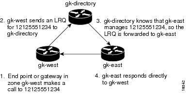
The following example selects one gatekeeper as the directory gatekeeper. See the following figure:
Examples
On the directory gatekeeper called gk-directory, identify all the prefixes for all the gatekeepers in your administrative domain:
zone local gk-directory cisco.com
zone remote gk-west cisco.com 172.16.1.1
zone remote gk-east cisco.com 172.16.2.1
zone prefix gk-west 1408.......
zone prefix gk-west 1415.......
zone prefix gk-west 1213.......
zone prefix gk-west 1650.......
zone prefix gk-east 1212.......
zone prefix gk-east 1617.......
lrq forward-queries
Examples
On the gatekeeper called gk-west, configure all the locally managed prefixes for that gatekeeper:
zone local gk-west cisco.com
zone remote gk-directory cisco.com 172.16.2.3
zone prefix gk-west 1408.......
zone prefix gk-west 1415.......
zone prefix gk-west 1213.......
zone prefix gk-west 1650.......
zone prefix gk-directory *
Examples
On the gatekeeper called gk-east, configure all the locally managed prefixes for that gatekeeper:
zone local gk-east cisco.com
zone remote gk-directory cisco.com 172.16.2.3
zone prefix gk-east 1212.......
zone prefix gk-east 1617.......
zone prefix gk-directory *
When an endpoint or gateway in zone gk-west makes a call to 12125551234, gk-west sends an LRQ message for that E.164 address to gk-directory, which forwards the message to gk-east. Gatekeeper gk-east responds directly to gk-west.
lrq lrj immediate-advance
To enable the Cisco IOS gatekeeper to immediately send a sequential location request (LRQ) message to the next zone after it receives a location reject (LRJ) message from a gatekeeper in the current zone, use the lrq lrj immediate-advance command in gatekeeper configuration mode. To disable this function, use the no form of this command.
Usage Guidelines
In a network in which LRQ messages are forwarded through multiple gatekeepers along a single path, a single LRQ message sent from a gatekeeper could solicit multiple LRJ and location confirmation (LCF) responses. If an LRJ response is received first, a potentially unnecessary LRQ message could be sent to the next zone, increasing traffic.
To avoid this problem, perform the following:
Examples
The following example enables the gatekeeper to immediately send a sequential LRQ message to the next zone after it receives an LRJ message from a gatekeeper in the current zone.
lrq lrj immediate-advancelrq reject-resource-low
lrq reject-unknown-circuit
To enable the gatekeeper to reject a location request (LRQ) message that contains an unknown destination circuit, use the lrq reject-unknown-circuitcommand in gatekeeper configuration mode. To disable the rejection, use the no form of this command.
Usage Guidelines
The gatekeeper checks the destination circuit field in each LRQ message. If the field contains a circuit unknown to the gatekeeper and thiscommandis entered, the gatekeeper rejects the LRQ request. If thiscommand is disabled, the gatekeeper tries to resolve the alias without considering the circuit.
lrq reject-unknown-prefix
To enable the gatekeeper to reject all location request (LRQ) messages for zone prefixes that are not configured, use the lrq reject-unknown-prefix command in gatekeeper configuration mode. To reenable the gatekeeper to accept and process all incoming LRQ messages, use the no form of this command.
Usage Guidelines
Use this command to configure the gatekeeper to reject any incoming LRQ messages for a destination E.164 address that does not match any of the configured zone prefixes.
Whether or not you use this command, the following is true when the E.164 address matches a zone prefix:
- If the matching zone prefix is local (that is, controlled by this gatekeeper), the LRQ message is serviced.
- If the matching zone prefix is remote (that is, controlled by some other gatekeeper), the LRQ message is rejected.
If you do not use this command and the target address does not match any known local or remote prefix, the default behavior is to attempt to service the call using one of the local zones. If this default behavior is not suitable for your site, use this command on your router to force the gatekeeper to reject such requests.
Examples
Consider the following gatekeeper configuration:
zone local gk408 cisco.com
zone local gk415 cisco.com
zone prefix gk408 1408.......
zone prefix gk415 1415.......
lrq reject-unknown-prefix
In this sample configuration, the gatekeeper is configured to manage two zones. One zone contains gateways with interfaces in the 408 area code, and the second zone contains gateways in the 415 area code. Then using the zone prefix command, the gatekeeper is configured with the appropriate prefixes so that calls to those area codes hop off in the optimal zone.
Now say some other zone has been erroneously configured to route calls to the 212 area code to this gatekeeper. When the LRQ message for a number in the 212 area code arrives at this gatekeeper, the gatekeeper fails to match the area code, and the message is rejected.
If this was your only site that had any gateways in it and you wanted your other sites to route all calls that require gateways to this gatekeeper, you can undo the lrq reject-unknown-prefix command by simply using the no lrq reject-unknown-prefix command.Now when the gatekeeper receives an LRQ message for the address 12125551234, it attempts to find an appropriate gateway in either one of the zones gk408 or gk415 to service the call.
lrq timeout blast window