-
Cisco IOS Quality of Service Solutions Command Reference
-
A through C
-
D through F
-
identity policy policy-map through ip rsvp pq-profile
-
ip rsvp precedence through load protocol
-
match access-group through mls ip pbr
-
mls qos global configuration mode through mpls experimental
-
N through P
-
Q through R
-
send qdm message through show atm bundle svc statistics
-
show auto discovery qos through show ip rsvp hello client lsp detail
-
show ip rsvp hello client lsp summary through show lane qos database
-
show mls qos through wrr-queue threshold
-
Index
-
 Feedback
Contents
N through P
- non-tcp
- non-tcp contexts
- oam-bundle
- platform ip features sequential
- platform ipsec fips-mode
- platform ipsec llq
- platform punt-police queue
- platform qos marker-statistics
- platform qos match-statistics per-ace
- platform qos match-statistics per-filter
- platform vfi dot1q-transparency
- plim qos input
- plim qos input map
- plim qos input map cos (classify CoS values for VLAN)
- police
- police (EtherSwitch)
- police (percent)
- police (policy map)
- police (two rates)
- police rate (control-plane)
- police rate pdp
- policy-map
- policy-map copp-peruser
- precedence
- precedence (WRED group)
- preempt-priority
- priority
- priority (10000 series)
- priority (SIP400)
- priority-group
- priority level
- priority-list default
- priority-list interface
- priority-list protocol
- priority-list queue-limit
- priority-queue cos-map
- priority-queue queue-limit
- pvc-bundle
non-tcp
To enable non-Transmission-Control-Protocol (non-TCP) header compression within an IP Header Compression (IPHC) profile, use the non-tcpcommand in IPHC-profile configuration mode. To disable non-TCP header compression within an IPHC profile, use the no form of this command.
Usage Guidelines
Intended for Use with IPHC Profiles
The non-tcpcommand is intended for use as part of an IPHC profile. An IPHC profile is used to enable and configure header compression on a network. For more information about using IPHC profiles to configure header compression, see the “Header Compression” module and the “Configuring Header Compression Using IPHC Profiles” module of the Cisco IOS Quality of Service Solutions Configuration Guide, Release 12.4T.
non-tcp contexts
To set the number of contexts available for non-Transmission-Control-Protocol (TCP) header compression, use the non-tcpcontexts command in IPHC-profile configuration mode. To remove the number of previously configured contexts, use the no form of this command.
Syntax Description
absolute
Indicates that the maximum number of compressed non-TCP contexts will be based on a fixed (absolute) number.
number-of-connections
Number of non-TCP connections. Range is from 1 to 1000.
kbps-per-context
Indicates that the maximum number of compressed non-TCP contexts will be based on available bandwidth.
kbps
Number of kbps to allow for each context. Range is from 1 to 100.
Command Default
The non-tcpcontexts command calculates the number of contexts on the basis of bandwidth and allocates 4 kbps per context.
Usage Guidelines
Use the non-tcpcontexts command to set the number of contexts available for non-TCP header compression. A context is the state that the compressor uses to compress a header and that the decompressor uses to decompress a header. The context is the uncompressed version of the last header sent and includes information used to compress and decompress the packet.
Intended for Use with IPHC Profiles
The non-tcpcontextscommand is intended for use as part of an IPHC profile. An IPHC profile is used to enable and configure header compression on your network. For more information about using IPHC profiles to configure header compression, see the “Header Compression” module and the “Configuring Header Compression Using IPHC Profiles” module of the Cisco IOS Quality of Service Solutions Configuration Guide , Release 12.4T.
Setting the Number of Contexts as an Absolute Number
The non-tcpcontextscommand allows you to set the number of contexts as an absolute number. To set the number of contexts as an absolute number, enter a number between 1 and 1000.
Calculating the Number of Contexts on the Basis of Bandwidth
The non-tcpcontextscommand can calculate the number of contexts on the basis of the bandwidth available on the network link to which the IPHC profile is applied.
To have the number of contexts calculated on the basis of the available bandwidth, enter the kbps-per-contextkeyword followed by a value for the kbps argument. The command divides the available bandwidth by the kbps specified. For example, if the bandwidth of the network link is 3000 kbps, and you enter 5 for the kbps argument, the command calculates 600 contexts.
Examples
The following is an example of an IPHC profile called profile2. In this example, the number of non-TCP contexts has been set to 75.
Router> enable Router# configure terminal Router(config)# iphc-profile profile2 ietf Router(config-iphcp)# non-tcp contexts absolute 75 Router(config-iphcp)# endoam-bundle
To enable end-to-end F5 Operation, Administration, and Maintenance (OAM) loopback cell generation and OAM management for all virtual circuit (VC) members of a bundle or a VC class that can be applied to a VC bundle, use the oam-bundle command in SVC-bundle configuration mode or VC-class configuration mode. To remove OAM management from the bundle or class configuration, use the no form of this command.
To enable end-to-end F5 OAM loopback cell generation and OAM management for all VC members of a bundle, use the oam-bundle command in bundle configuration mode. To remove OAM management from the bundle, use the no form of this command.
Syntax Description
manage
(Optional) Enables OAM management. If this keyword is omitted, loopback cells are sent, but the bundle is not managed.
frequency
(Optional) Number of seconds between transmitted OAM loopback cells. Values range from 0 to 600 seconds. The default value for the frequency argument is 10 seconds.
Command Default
End-to-end F5 OAM loopback cell generation and OAM management are disabled, but if OAM cells are received, they are looped back.
Command Modes
SVC-bundle configuration (for an SVC bundle)
VC-class configuration (for a VC class)
Bundle configuration (for an ATM VC bundle)Command History
Release
Modification
12.0(3)T
This command was introduced.
12.0(26)S
This command was introduced on the Cisco 10000 series router.
12.2(16)BX
This command was implemented on the ESR-PRE2.
12.2(4)T
This command was made available in SVC-bundle configuration mode.
12.2(33)SRA
This command was integrated into Cisco IOS Release 12.2(33)SRA.
12.2(31)SB
This command was integrated into Cisco IOS Release 12.2(31)SB.
12.2SX
This command is supported in the Cisco IOS Release 12.2SX train. Support in a specific 12.2SX release of this train depends on your feature set, platform, and platform hardware.
Usage Guidelines
This command defines whether a VC bundle is OAM managed. If this command is configured for a bundle, every VC member of the bundle is OAM managed. If OAM management is enabled, further control of OAM management is configured using the oamretrycommand.
This command has no effect if the VC class that contains the command is attached to a standalone VC; that is, if the VC is not a bundle member. In this case, the attributes are ignored by the VC.
To use this command in VC-class configuration mode, first enter the vc-classatm global configuration command.
To use this command in bundle configuration mode, first enter the bundle subinterface configuration command to create the bundle or to specify an existing bundle.
VCs in a VC bundle are subject to the following configuration inheritance rules (listed in order of next-highest precedence):
- VC configuration in bundle-VC mode
- Bundle configuration in bundle mode (with the effect of assigned VC-class configuration)
Examples
The following example enables OAM management for a bundle called “bundle 1”:
bundle bundle1
 oam-bundle manage
Related Commands
Command
Description
broadcast
Configures broadcast packet duplication and transmission for an ATM VC class, PVC, SVC, or VC bundle.
bundle
Enters bundle configuration mode to create a bundle or modify an existing bundle.
class-bundle
Configures a VC bundle with the bundle-level commands contained in the specified VC class.
encapsulation
Sets the encapsulation method used by the interface.
inarp
Configures the Inverse ARP time period for an ATM PVC, VC class, or VC bundle.
oam retry
Configures parameters related to OAM management for an ATM PVC, SVC, VC class, or VC bundle.
protocol (ATM)
Configures a static map for an ATM PVC, SVC, VC class, or VC bundle, and enables Inverse ARP or Inverse ARP broadcasts on an ATM PVC by configuring Inverse ARP either directly on the PVC, on the VC bundle, or in a VC class (applies to IP and IPX protocols only).
vc-class atm
Creates a virtual circuit (VC) class for an ATM permanent virtual circuit (PVC), switched virtual circuit (SVC), or ATM interface.
platform ip features sequential
To enable Internet Protocol (IP) precedence-based or differentiated services code point (DSCP)-based egress quality of service (QoS) filtering to use any IP precedence or DSCP policing or marking changes made by ingress policy feature card (PFC) QoS, use the platformipfeaturessequential command in interface configuration mode. To return to the default settings, use the no form of this command.
platform ip features sequential [ access-group { ip-acl-name | ip-acl-number } ]
no platform ip features sequential [ access-group { ip-acl-name | ip-acl-number } ]
Syntax Description
access-group ip-acl-name
(Optional) Specifies the name of the ACL that is used to specify the match criteria for the recirculation packets.
access-group ip-acl-number
(Optional) Specifies the number of the ACL that is used to specify the match criteria for the recirculation packets; valid values are from 1 to 199 and from 1300 to 2699.
Command Default
IP precedence-based or DSCP-based egress QoS filtering uses received IP precedence or DSCP values and does not use any IP precedence or DSCP changes made by ingress QoS as the result of policing or marking.
Usage Guidelines
Caution
If the switch is operating in PFC3A mode with egress ACL support for remarked DSCP configured, when the PFC3 processes traffic to apply ingress PFC QoS, it applies ingress PFC QoS filtering and ingress PFC QoS, and incorrectly applies any egress QoS filtering and egress PFC QoS configured on the ingress interface, which results in unexpected behavior if QoS filtering is configured on an interface where egress ACL support for remarked DSCP is enabled. This problem does not occur in other PFC3 modes.
The enhanced egress-QoS filtering enables the IP precedence-based or DSCP-based egress-QoS filtering to use any IP precedence or DSCP policing or marking changes made by ingress QoS.
The nonenhanced egress-QoS filtering behavior is the normal Cisco 7600 series router or the Catalyst 6500 series switch behavior when QoS is applied in the hardware.
The PFC3 provides egress PFC QoS only for Layer 3-switched and routed traffic on egress Layer 3 interfaces (either LAN ports configured as Layer 3 interfaces or VLAN interfaces).
You configure enhanced egress QoS filtering on ingress Layer 3 interfaces (either LAN ports configured as Layer 3 interfaces or VLAN interfaces).
To enable enhanced egress QoS filtering only for the traffic filtered by a specific standard, extended named, or extended numbered IP ACL, enter the IP ACL name or number.
If you do not enter an IP ACL name or number, enhanced egress QoS filtering is enabled for all IP ingress IP traffic on the interface.
NoteWhen you configure enhanced egress-QoS filtering, the PFC3A processes traffic to apply ingress PFC QoS. The PFC3A applies ingress-QoS filtering and Cisco 7600 series router or the Catalyst 6500 series switch hardware ingress QoS. The PFC3A incorrectly applies any egress-QoS filtering and Cisco 7600 series router or the Catalyst 6500 series switch hardware egress QoS that is configured on the ingress interface.
NoteIf you configure enhanced egress-QoS filtering on an interface that uses Layer 2 features to match the IP precedence or DSCP as modified by ingress-QoS marking, the packets are redirected or dropped and prevented from being processed by egress QoS.
NoteIf you enable enhanced egress-QoS filtering, the hardware acceleration of NetFlow-based features such as reflexive ACL, NAT, and TCP intercept are disabled.
To verify configuration, use the showrunning-configinterface command.
platform ipsec fips-mode
To enable the Federal Information Processing Standard (FIPS) and hardware entropy, use the platform ipsec fips-mode command in the global configuration mode. To disable the FIPS and hardware entropy, use the no form of this command.
Syntax Description
Command History
Release Modification Cisco IOS XE Release 3.7.3S
This command was introduced on the Cisco ASR 1000 Series Aggregation Services Routers.
platform ipsec llq
To enable low latency queuing (LLQ) for quality of service (QoS) groups, use the platform ipsec llq command in global configuration mode. To disable LLQ use the no version of this command.
Usage Guidelines
This command allows users to configure specified QoS groups as high priority for IPsec on tunnel interfaces where Tunnel Protection is used. This prevents high priority packets from being queued to the default queue, thus reducing latency and traffic loss during oversubscription.
platform punt-police queue
To enable punt policing on a queue, and to specify the maximum punt rate and burst rate on a per-queue basis, use the platform punt-police queue command in global configuration mode. To return to the default settings, use the no form of this command.
platform punt-police queue queue-id max-punt-rate max-burst-rate
no platform punt-police queue queue-id
Syntax Description
queue-id
Unique number that identifies the queue. Valid range is a number from 0 to 28.
max-punt-rate
Maximum punt-rate for the queue, in packets per second (pps). Valid range is a number from 10 to 10000.
max-burst-rate
Maximum burst-rate for the queue, in packets per second (pps). Valid range is a number from 1000 to 10000.
Command Default
Punt policing is enabled on the queues. See the table in the “Usage Guidelines” section for a list of the defaults for each queue.
Usage Guidelines
Punt policing protects a Route Processor (RP) from having to process noncritical traffic. Traffic is placed on different CPU queues based on various criteria. You can then configure the maximum punt rate on a per-queue basis. By default, no explicit policing is done on a queue.
Note
Traffic on a certain CPU queue could be dropped, irrespective of the configured punt rate, based on the queue priority, queue size, or traffic punt rate.
To verify the configuration, use the show platform software infrastructure punt statistics command.
Punt policing is enabled by default. The following table shows the default punt policing settings for each queue:
Table 1 Default Punt Policing Settings Ring /Queue
Queue Name
Punt Rate (pps)
Burst Rate (pps)
0
SW FORWARDING Q
500
1000
1
ROUTING PROTOCOL Q
500
1000
2
ICMP Q
500
1000
3
HOST Q
1000
2000
4
ACL LOGGIN Q
500
1000
5
STP Q
3000
6000
6
L2 PROTOCOL Q
1000
2000
7
MCAST CONTROL Q
1000
2000
8
BROADCAST Q
500
1000
9
REP Q
3000
6000
10
CFM Q
3000
6000
11
CONTROL Q
1000
2000
12
IP MPLS TTL Q
1000
2000
13
DEFAULT MCAST Q
500
1000
14
MCAST ROUTE DATA Q
500
1000
15
MCAST MISMATCH Q
500
1000
16
RPF FAIL Q
500
1000
17
ROUTING THROTTLE Q
500
1000
18
MCAST Q
500
1000
19
MPLS OAM
1000
2000
20
IP MPLS MTU
500
1000
21
PTP Q
3000
6000
22
LINUX ND Q
500
1000
23
KEEPALIVE Q
1000
2000
24
ESMC Q
3000
6000
25
FPGA BFD Q
3000
6000
26
FPGA CCM Q
3000
6000
27
FPGA CFE Q
3000
6000
28
L2PT DUP Q
4000
8000
platform qos marker-statistics
To display the number of packets that have modified headers and have been classified into a category for local router processing at a system-wide (platform) level, use the platformqosmarker-statistics command in global configuration mode. To disable displaying the QoS: Packet Marking Statistics feature, use the no form of this command.
Usage Guidelines
Ensure no policy maps are associated with interfaces on the system. If there are, the system returns the following message:
Either a) A system RELOAD or
       b) Remove all service-policies, re-apply the change
            to the statistics, re-apply all service-policies
			is required before this command will be activated.
Enabling the Qos: Packet Marking Statistics feature may increase CPU utilization on a scaled configuration. Before enabling the Qos: Packet Marking Statistics feature, weigh the benefits of the statistics information against the increased CPU utilization for your system.
Examples
The following example shows how to do the following:
- Enable the QoS: Packet Marking Statistics feature
- Configure an input service policy on an ingress interface
- Classify traffic to a configured class
- Configure marking in the class to set the IP precedence to 1
- Display the showpolicy-mapinterface command output
Router#
platform qos marker-statistics

class-map test_class
    match access-group 101
  policy-map test_policy
    class test_class
       set ip precedence 1
Interface POS2/0/1
  service-policy input test_policy
Router#
show policy-map interface
POS2/0/1
  Service-policy input: test_policy
    Class-map: test_class (match-all)
      6644560 packets, 757479840 bytes
      5 minute offered rate 8720000 bps, drop rate 0000 bps
      Match:  precedence 5
      QoS Set
        precedence 1
          Packets marked 6644560
    Class-map: class-default (match-any)
      18 packets, 1612 bytes
      5 minute offered rate 0000 bps, drop rate 0000 bps
      Match: any
Related Commands
Command
Description
show platform hardware qfp active feature qos config global
Displays whether the QoS: Packet Marking Statistics feature is enabled.
show policy-map interface
Displays packet statistics of all classes that are configured for all service policies either on the specified interface or subinterface or on a specific PVC on the interface.
show policy-map session
Displays the QoS policy map in effect for a PPPoE session.
platform qos match-statistics per-ace
To enable the quality of service (QoS) packet-matching statistics to count the number of packets and bytes matching individual access control elements (ACEs) used in QoS policies, use the platform qos match-statistics per-ace command in global configuration mode. To disable the QoS packet-matching statistics per ACE, use the no form of this command.
Usage Guidelines
You must configure the platform qos match-statistics per-filter command to enable QoS per-filter packet-matching statistics before you configure the platform qos match-statistics per-ace command to enable QoS per-ACE packet-matching statistics.
Ensure that policy maps are not associated with the interfaces on the system. If they are, the system returns the following message:
Either a) A system RELOAD or
       b) Remove all service-policies, re-apply the change
          to the statistics, re-apply all service-policies
			is required before this command will be activated.
Enabling the Per ACE QoS Statistics feature may increase CPU utilization on a scaled configuration. Before you enable it you should weigh the benefits of the statistics information against the increased CPU utilization on the system.
Examples
The following example shows how to configure a per-ACE filter for a QoS policy map:
Device(config)# platform qos match-statistics per-filter
Device(config)# platform qos match-statistics per-ace
Related Commands
Command
Description
class-map match-any
Creates a class map to be used for matching packets to a specified class.
platform qos match-statistics per-filter
Enables QoS per-filter packet matching statistics at the system-wide (platform) level.
show access lists
Displays ACE statistics for all configured ACLs including those used in QoS service policies.
show platform hardware qfp active feature qos config global
Displays whether the QoS Packet Matching Statistics feature is enabled.
show policy-map interface
Displays packet statistics of all classes that are configured for all service policies either on the specified interface or subinterface or on a specific PVC on the interface.
platform qos match-statistics per-filter
To define a QoS packet filter at the system-wide (platform) level, then display the number of packets and bytes matching that filter, use the platformqosmatch-statisticsper-filter command in global configuration mode. To stop filtering, use the no form of this command.
Usage Guidelines
Ensure no policy maps are associated with interfaces on the system. If there are, the system returns the following message:
Either a) A system RELOAD or
       b) Remove all service-policies, re-apply the change
            to the statistics, re-apply all service-policies
			is required before this command will be activated.
Enabling the QoS: Packet Matching Statistics feature may increase CPU utilization on a scaled configuration. Before enabling QoS: Packet Matching Statistics, weigh the benefits of the statistics information against the increased CPU utilization for your system.
Ensure you have defined a filter using the class-map
 command with the match-any
 keyword.
Examples
The following example shows you how to use the this command:
Router>
enable
Router#
configure terminal
Router(config)#
platform qos match-statistics per-filter
Router# end
Related Commands
Command
Description
class-map match-any
Creates a class map to be used for matching packets to a specified class.
show platform hardware qfp active feature qos config global
Displays whether or not the QoS: Packet Matching Statistics feature is currently enabled.
show policy-map interface
Displays packet statistics of all classes that are configured for all service policies either on the specified interface or subinterface or on a specific PVC on the interface.
platform vfi dot1q-transparency
To enable 802.1Q transparency mode, use theplatformvfidot1q-transparency command in global configuration mode. To disable 802.1Q transparency, use the no form of this command.
Usage Guidelines
This command is supported on Optical Services Modules (OSMs) only.
802.1Q transparency allows a service provider to modify the Multiprotcol Label Switching Experimental bits (MPLS EXP) bits for core-based QoS policies while leaving any Virtual Private LAN Service (VPLS) customer 802.1p bits unchanged.
With releases before Cisco IOS Release 12.2(18)SXF1, application of a service policy to a VLAN interface that matches all and sets the MPLS EXP bits had an effect on both the Interior Gateway Protocol (IGP) label and the VC label. Because the 802.1p bits were rewritten on the egress Provider Edge (PE) based on the received Virtual Circuit (VC) MPLS EXP bits, the VPLS customer’s 802.1p bits were changed.
The Dot1q Transparency for EoMPLS feature causes the VLAN-applied policy to affect only the IGP label (for core QoS) and leaves the VC label EXP bits equal to the 802.1p bits. On the egress PE, the 802.1p bits are still rewritten based on the received VC EXP bits; however, because the EXP bits now match the ingress 802.1p bits, a VPLS customer’s 802.1p bits do not change.
Global configuration applies to all virtual forwarding instance (VFI) and switched virtual interface (SVI) EoMPLS VCs configured on the Cisco 7600 series routers.
To ensure interoperability, apply the Dot1q Transparency for EoMPLS feature to all participating PE routers.
plim qos input
To attach an ingress classification template to an interface of Packet over SONET (POS), channelized, and clear-channel SPAs, use the plim qos input class-map class-map indexcommandin interface configuration mode. To assign excess weight value to the low-priority packets on an interface for a clear-channel SPA, use the plim qos input weight weight-value command. To remove the ingress classification template assignment for a specified index, use the noform of the plim qos input class-mapcommand. To remove excess scheduling of low-priority packets from an interface, use the no form of plim qos input weight command.
plim qos input { class-map class-map index | weight weight-value }
no plim qos input { class-map class-map index | weight }
Syntax Description
class-map
Maps the ingress classification template class map to the interface.
class-map index
The index classification template number for which the classification criteria is applied to the interface.
weight
Schedules the weight assigned to an interface to share excess bandwidth among low priority packets.
weight-value
The weight value assigned to an interface to share excess bandwidth among low priority packets. The excess bandwidth assigned to the interface is relative and dependent on free bandwith assigned to other interfaces and the free bandwidth available. The valid range is 40 to 10000.
Usage Guidelines
The classification template-specific details are defined in the template, and the template is attached to an interface using the plim qos input class-mapclass-map indexcommand. The classification template can be deleted using the no form of the command. The plim qos input class-mapclass-mapi ndex command is applicable to POS SPA, channelized SPA, and clear-channel SPA.
The plim qos input weightweight-value command is used to assign sharing of excess bandwidth for low priority packets. The plim qos input weightweight-valuecommand is used to assign weight to an interface, and depending on the relative weight assigned to other interfaces, bandwidth is shared among the interfaces. The excess bandwidth is allocated after the high priority packets are processed.
NoteThe plim qos input weightweight-valuecommand is applicable to only clear-channel SPAs.
NoteThe option to configure minimum bandwidth for ‘strict-priority’ queue at port-level (interface-level) is deprecated as it is not applicable to the current mode of operation. Existing configuration will be rejected with an error.
NoteThe plim qos input command is not supported from the CEM interface on the Circuit Emulation over Packet (CEoP) OC-3 SPA on Cisco ASR 1000 Series Routers.
NoteThis plim qos input is not supported from the CEM interface on the Channelized T1/E1 (CTE1) CEoP SPA on Cisco ASR 1000 Series Routers.
The following commands are present in command-line interface but do not have any effect on the CEoP OC3 SPA and CTE1 CEoP SPA on Cisco ASR 1000 Series Routers. If you configure one of these commands, a message stating that the command is not supported on the CEoP OC3 SPA is displayed. When either these commands are configured, a message stating the same is displayed on the Cisco ASR 1000 Series Router:
hw-module subslot {slot/subslot} qos input {{policer bandwidth bandwidth strict-policy} | weight weight}}
Examples
The following example shows how to attach a classification template to an interface using the plim qos input class-mapclass-map index command:
Router# config
Router(config)# interface POS 0/2/0
Router(config-if)# plim qos input class-map
2
The following example shows how to assign a weight of 50 to an interface to enable sharing of excess bandwidth among low priority packets using the plim qos input weight50command:
Router# config Router(config)# interface POS 0/2/0 Router(config-if)# plim qos input weight 50plim qos input map
To configure a priority queue on Gigabit Ethernet Shared Port Adaptors (SPAs), use the plim qos input map command in the interface configuration mode or the subinterface configuration mode. To remove a priority queue, use the no form of this command.
plim qos input map { cos { enable | cos-value queue low-latency} | ip { precedence-based | precedence precedence-value queue low-latency} | ipv6 tc tc-value queue low-latency | mpls exp exp-value queue low-latency
no plim qos input map { cos { enable | cos-value queue low-latency} | ip { precedence-based | precedence precedence-value queue low-latency} | ipv6 tc tc-value queue low-latency | mpls exp exp-value queue low-latency
Syntax Description
Usage Guidelines
The plim qos input map command separates high-priority traffic from low-priority traffic and places the traffic in the appropriate interface queue. The command separates priority and non-priority traffic at the SPA interface processor (SIP) to prevent the dropping of high-priority traffic in an oversubscription scenario. Each SPA supports one priority queue.
The router supports the following classification types for the prioritization of ingress traffic on the Gigabit Ethernet SPAs:In the plim qos input map ip dscp dscp-value queue low-latency command, valid values for dscp-value can be one of the following:
- 0 to 63—Differentiated services codepoint value
- af11—001010
- af12—001100
- af13—001110
- af21—010010
- af22—010100
- af23—010110
- af31—011010
- af32—011100
- af33—011110
- af41—100010
- af42—100100
- af43—100110
- cs1—Precedence 1 (001000)
- cs2—Precedence 2 (010000)
- cs3—Precedence 3 (011000)
- cs4—Precedence 4 (100000)
- cs5—Precedence 5 (101000)
- cs6—Precedence 6 (110000)
- cs7—Precedence 7 (111000)
- default—000000
- ef—101110
In the plim qos input map ipv6 tc tc-value queue low-latency command, valid values for tc-value can be one of the following:
- 0 to 63—Differentiated services codepoint value
- af11—001010
- af12—001100
- af13—001110
- af21—010010
- af22—010100
- af23—010110
- af31—011010
- af32—011100
- af33—011110
- af41—100010
- af42—100100
- af43—100110
- cs1—Precedence 1 (001000)
- cs2—Precedence 2 (010000)
- cs3—Precedence 3 (011000)
- cs4—Precedence 4 (100000)
- cs5—Precedence 5 (101000)
- cs6—Precedence 6 (110000)
- cs7—Precedence 7 (111000)
- default—000000
- ef—101110
Examples
The following example shows how to use the plim qos input map ip dscp-based command to enable DSCP-based classification on the SPA that is located in subslot 0 of the SIP in slot 1 of a Cisco 10000 Series Router:
Router(config)# interface gigabitethernet 3/0/1
Router(config-if)# plim qos input map ip dscp-based
The following example shows how to use the plim qos input map command to classify incoming IP traffic according to the value of the DSCP bits, and place the traffic into the appropriate queue on an ATM interface on a Cisco ASR 1000 Series Router:
Router# configure terminal Router(config)# interface ATM0/1/0 Router(config-if)# plim qos input map ip dscp af11 - af12 queue strict-priority Router(config-if)# plim qos input map ipv6 tc af11 - af12 queue strict-priority Router(config-if)# plim qos input map mpls exp 7 queue 0plim qos input map cos (classify CoS values for VLAN)
To classify ingress traffic on Ethernet shared port adapters (SPAs) based on the Class of Service (CoS) value or CoS range of either the inner or the outer VLAN tag of a QinQ subinterface as either high priority (low latency) or low priority (queue 0), use the plim qos input map cos command in subinterface configuration mode. To disable the CoS-based classification, use the no form of this command.
Syntax for Classifying the CoS Values for an Inner VLAN as High Priority or Low Priority
plim qos input map cos { enable | inner-based | inner { cos-value | cos-range } queue { strict-priority | 0 } }
no plim qos input map cos enable
Syntax for Classifying the CoS Values for an Outer VLAN as High Priority or Low Priority
plim qos input map cos { enable | outer-based | outer { cos-value | cos-range } queue { strict-priority | 0 } }
no plim qos input map cos enable
Syntax Description
enable
Enables IEEE 802.1Q CoS-based classification.
inner-based
Enables an inner VLAN-based classification. Before you can configure the CoS values for an inner VLAN, you must first enable the inner VLAN-based classification.
outer-based
Enables an outer VLAN-based classification. Before you can configure the CoS values for an outer VLAN, you must first enable the outer VLAN-based classification.
inner
Allows you to configure the CoS value or range that requires strict priority for inner VLANs.
outer
Allows you to configure the CoS value or range that requires strict priority for outer VLANs.
cos-value
The inner or outer VLAN CoS value for which you want to classify the packets mapping the CoS value as high priority or low priority.
cos-range
The inner or outer VLAN CoS range for which you want to classify the packets mapping the CoS range as high priority or low priority.
queue
Enables the classification of inner or outer VLAN CoS values or CoS range as high priority or low priority.
strict-priority
Classifies the specified CoS value or range as high priority (low latency).
0
Classifies the specified CoS value or range as low priority (queue 0).
Configuring CoS-based Classification for an Inner VLAN
Before you can classify ingress traffic based on inner VLAN CoS values, you must first enable the inner VLAN CoS-based classification using the plim qos input map cos inner-based command.
Configuring CoS-based Classification for an Outer VLAN
Before you can classify ingress traffic based on outer VLAN CoS values, you must first enable the outer VLAN CoS-based classification using the plim qos input map cos outer-based command.
To disable the CoS-based classification at the subinterface level and enable the Layer 3 information-based classification at the main interface level, use the no plim qos input map cos enable command in subinterface configuration mode. Once the no plim qos input map cos enable command is configured, a message indicating that the main interface-level classification configuration will be applicable is displayed.
NoteWith CSCtd91658, if you try to configure CoS-based classification for an inner VLAN on a subinterface that already has classification based on an outer VLAN (or vice versa), or if you try to remove a non-existent CoS-based classification, a warning message is displayed.
NoteThe plim qos input map cos command is supported only on Ethernet SPAs. The plim qos input map cos command is executed from VLAN subinterface configuration mode under a QinQ subinterface.
Examples
The following example shows how to classify a CoS value of 3 of an inner VLAN as high priority:
Router# configure terminal
Router(config)# interface gigabitethernet 0/0/0.1
Router(config-subif)# plim qos input map cos inner-based
Router(config-subif)# plim qos input map cos inner 3 queue strict-priority
The following example shows how to classify a CoS value of 3 of an outer VLAN as high priority:
Router# configure terminal
Router(config)# interface gigabitethernet 0/0/0.1
Router(config-subif)# plim qos input map cos outer-based
Router(config-subif)# plim qos input map cos outer 3 queue strict-priority
The following example shows how to enable the IEEE 802.1Q CoS-based classification in QinQ subinterface configuration mode:
Router# configure terminal
Router(config)# interface gigabitethernet 0/0/0.2
Router(config-subif)# encapsulation dot1q 2 second-dot1q 100
Router(config-subif)# plim qos input map cos enable
The following example shows how to disable IEEE 802.1Q CoS-based classification in QinQ subinterface configuration mode. A message is displayed indicating that the main interface-level classification configuration will be applicable.
Router# configure terminal
Router(config)# interface gigabitethernet 0/0/0.2
Router(config-subif)# encapsulation dot1q 2 second-dot1q 100
Router(config-subif)# no plim qos input map cos enable
%Classification will now be based on Main interface configuration.
The following example shows how to enable IEEE 802.1Q CoS-based classification in Dot1Q subinterface configuration mode:
Router# configure terminal
Router(config)# interface gigabitethernet 0/0/0.1
Router(config-subif)# encapsulation dot1Q 1 native
Router(config-subif)# plim qos input map cos enable
The following example shows how to disable IEEE 802.1Q CoS-based classification in Dot1Q subinterface configuration mode. A message is displayed indicating that the main interface-level classification configuration will be applicable.
Router# configure terminal
Router(config)# interface gigabitethernet 0/0/0.1
Router(config-subif)# encapsulation dot1Q 1 native
Router(config-subif)# no plim qos input map cos enable
%Classification will now be based on Main interface configuration.
The following example shows how to use the plim qos input map command to classify incoming IP traffic according to the value of the DSCP bits, and place the traffic into the appropriate queue on an ATM interface on a Cisco ASR 1000 Series Router.
Router# configure terminal Router(config)# interface ATM0/1/0 Router(config-if)# plim qos input map ip dscp af11 - af12 queue strict-priority Router(config-if)# plim qos input map ipv6 tc af11 - af12 queue strict-priority Router(config-if)# plim qos input map mpls exp 7 queue 0police
To configure traffic policing, use the police command in policy-map class configuration mode or policy-map class police configuration mode. To remove traffic policing from the configuration, use the no form of this command.
police bps [burst-normal] [burst-max] conform-action action exceed-action action [ violate-action action ]
no police bps [burst-normal] [burst-max] conform-action action exceed-action action [ violate-action action ]
Syntax Description
bps
Average rate, in bits per second. Valid values are 8000 to 128000000000 (128 Gb/s).
burst-normal
(Optional) Normal burst size in bytes. Valid values are 1000 to 2000000000 (2 Gb). Default normal burst size is 1500.
burst-max
(Optional) Maximum burst size, in bytes. Valid values are 1000 to 2000000000 (2 Gb). Default varies by platform.
conform-action
Specifies the action to take on packets that conform to the rate limit.
exceed-action
Specifies the action to take on packets that exceed the rate limit.
violate-action
(Optional) Specifies the action to take on packets that violate the normal and maximum burst sizes.
action
Action to take on packets. Specify one of the following keywords:
- drop —Drops the packet.
- set-clp-transmit value—Sets the ATM Cell Loss Priority (CLP) bit from 0 to 1 on the ATM cell and transmits the packet with the ATM CLP bit set to 1.
- set-cos-inner-transmit value—Sets the inner class of service field as a policing action for a bridged frame on the Enhanced FlexWAN module when using bridging features on SPAs with the Cisco 7600 SIP-200 and Cisco 7600 SIP-400 on the Cisco 7600 series router.
- set-cos-transmit value—Sets the class of service (CoS) packet value and sends it.
- set-discard-class-transmit —Sets the discard class attribute of a packet and transmits the packet with the new discard class setting.
- set-dscp-transmit value—Sets the IP differentiated services code point (DSCP) value and transmits the packet with the new IP DSCP value.
- set-dscp-tunnel-transmit value—Sets the DSCP value (0 to 63) in the tunnel header of a Layer 2 Tunnel Protocol Version 3 (L2TPv3) or Generic Routing Encapsulation (GRE) tunneled packet for tunnel marking and transmits the packet with the new value.
- set-frde-transmit value—Sets the Frame Relay Discard Eligibility (DE) bit from 0 to 1 on the Frame Relay frame and transmits the packet with the DE bit set to 1.
- set-mpls-experimental-imposition-transmit value —Sets the Multiprotocol Label Switching (MPLS) experimental (EXP) bits (0 to 7) in the imposed label headers and transmits the packet with the new MPLS EXP bit value.
- set-mpls-experimental-topmost value—Rewrites the experimental value.
- set-mpls-experimental-topmost-transmit value—Sets the MPLS EXP field value in the topmost MPLS label header at the input and/or output interfaces.
- set-prec-transmit value—Sets the IP precedence and transmits the packet with the new IP precedence value.
- set-prec-tunnel-transmit value—Sets the precedence value (0 to 7) in the tunnel header of an L2TPv3 or GRE tunneled packet for tunnel marking and transmits the packet with the new value.
- set-qos-transmit value—Sets the QoS group value and transmits the packet with the new QoS group value.
- transmit —Transmits the packet. The packet is not altered.
Command Modes
Policy-map class configuration (config-pmap-c) when specifying a single action to be applied to a marked packet
Policy-map class police configuration (config-pmap-c-police) when specifying multiple actions to be applied to a marked packetCommand History
Release
Modification
12.0(5)XE
This command was introduced.
12.1(1)E
This command was integrated into Cisco IOS Release 12.1(1)E.
12.1(5)T
This command was integrated into Cisco IOS Release 12.1(5)T. The violate-action keyword was added.
12.2(2)T
This command was modified.
- The set-clp-transmit keyword for the action argument was added.
- The set-frde-transmit keyword for the action argument was added.
Note However, the set-frde-transmit keyword is not supported for AToM traffic in this release. Also, the set-frde-transmit keyword is supported only when Frame Relay is implemented on a physical interface without encapsulation.
12.2(8)T
This command was modified for the Policer Enhancement—Multiple Actions feature. This command can now accommodate multiple actions for packets marked as conforming to, exceeding, or violating a specific rate.
12.2(13)T
This command was modified. In the action argument, the set-mpls-experimental-transmit keyword was renamed to set-mpls-experimental-imposition-transmit.
12.2(28)SB
This command was modified. The set-dscp-tunnel-transmit and set-prec-tunnel-transmit keywords for the action argument were added. These keywords are intended for marking Layer 2 Tunnel Protocol Version 3 (L2TPv3) tunneled packets.
12.2(33)SRA
This command was modified. The set-cos-inner-transmit keyword for the action argument was added when using multipoint bridging (MPB) features on the Enhanced FlexWAN module and when using MPB on SPAs with the Cisco 7600 SIP-200 and Cisco 7600 SIP-400 on the Cisco 7600 series router.
12.2(31)SB2
This command was modified. Support for the set-frde-transmit action argument was added on the Cisco 10000 series router.
12.2SX
This command is supported in the Cisco IOS Release 12.2SX train. Support in a specific 12.2SX release of this train depends on your feature set, platform, and platform hardware.
12.2(33)SRC
This command was modified. Support for the Cisco 7600 series router was added.
12.4(15)T2
This command was modified to include support for marking Generic Routing Encapsulation (GRE) tunneled packets.
Note For this release, marking GRE-tunneled packets is supported only on platforms equipped with a Cisco MGX Route Processor Module (RPM-XF).
12.2(33)SB
This command was modified to include support for marking GRE-tunneled packets, and support for the Cisco 7300 series router was added.
15.1(1)T
This command was modified to include support for policing on SVI interfaces for Cisco ISR 1800, 2800, and 3800 series routers.
12.2(50)SY
This command was modified. Support for the set-mpls-experimental-topmost value argument was added.
15.0(1)SY
This command was modified. The maximum value for the bps, burst-normal, and burst-max arguments was increased.
Cisco IOS XE Release 3.5S
This command was modified. Support was added for the Cisco ASR 903 Router.
Usage Guidelines
Use the police command to mark a packet with different quality of service (QoS) values based on conformance to the service-level agreement.
In Cisco IOS release 12.2(50)SY, when you apply the set-mpls-experimental-topmost value in the egress direction the set-mpls-experimental-imposition value is blocked.
NoteIn Cisco IOS Release 15.0(1)SY and above, if you configure a policy map without specifying the burst size, then the default burst size can reach 2 Gb/s.
If you configure a high rate or high burst size and then change to a Cisco IOS software release that does not support your settings, the configuration is rejected on boot up and the police command is removed from the policy map.
Specifying Multiple Actions
The police command allows you to specify multiple policing actions. When specifying multiple policing actions when configuring the police command, note the following points:
- You can specify a maximum of four actions at one time.
- You cannot specify contradictory actions such as conform-action transmit and conform-action drop.
Using the police Command with the Traffic Policing Feature
The police command can be used with the Traffic Policing feature. The Traffic Policing feature works with a token bucket algorithm. Two types of token bucket algorithms are in Cisco IOS Release 12.1(5)T: a single-token bucket algorithm and a two-token bucket algorithm. A single-token bucket system is used when the violate-action option is not specified, and a two-token bucket system is used when the violate-action option is specified.
The token bucket algorithm for the police command that was introduced in Cisco IOS Release 12.0(5)XE is different from the token bucket algorithm for the police command that was introduced in Cisco IOS Release 12.1(5)T. For information on the token bucket algorithm introduced in Release 12.0(5)XE, see the Traffic Policing document for Release 12.0(5)XE. This document is available on the New Features for 12.0(5)XE documentation index (under Modular QoS CLI-related feature modules) at www.cisco.com.
The following are explanations of how the token bucket algorithms introduced in Cisco IOS Release 12.1(5)T work.
Token Bucket Algorithm with Single-Token Bucket
The single-token bucket algorithm is used when the violate-action option is not specified in the police command CLI.
The conform bucket is initially set to the full size (the full size is the number of bytes specified as the normal burst size).
When a packet of a given size (for example, “B” bytes) arrives at specific time (time “T”), the following actions occur:
- Tokens are updated in the conform bucket. If the previous arrival of the packet was at T1 and the current time is T, the bucket is updated with (T - T1) worth of bits based on the token arrival rate. The token arrival rate is calculated as follows:
(time between packets (which is equal to T - T1) * policer rate)/8 bytes
- If the number of bytes in conform bucket B is greater than or equal to the packet size, the packet conforms and the conform action is taken on the packet. If the packet conforms, B bytes are removed from the conform bucket and the conform action is completed for the packet.
- If the number of bytes in conform bucket B (minus the packet size to be limited) is fewer than 0, the exceed action is taken.
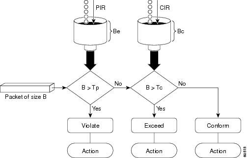
Token Bucket Algorithm with a Two-Token Bucket
The two-token bucket algorithm is used when the violate-action option is specified in the police command.
The conform bucket is initially full (the full size is the number of bytes specified as the normal burst size).
The exceed bucket is initially full (the full exceed bucket size is the number of bytes specified in the maximum burst size).
The tokens for both the conform and exceed token buckets are updated based on the token arrival rate, or committed information rate (CIR).
When a packet of given size (for example, “B” bytes) arrives at specific time (time “T”) the following actions occur:
- Tokens are updated in the conform bucket. If the previous arrival of the packet was at T1 and the current arrival of the packet is at T, the bucket is updated with T -T1 worth of bits based on the token arrival rate. The refill tokens are placed in the conform bucket. If the tokens overflow the conform bucket, the overflow tokens are placed in the exceed bucket.
The token arrival rate is calculated as follows:
(time between packets (which is equal to T-T1) * policer rate)/8 bytes
- If the number of bytes in conform bucket B is greater than or equal to the packet size, the packet conforms and the conform action is taken on the packet. If the packet conforms, B bytes are removed from the conform bucket and the conform action is taken. The exceed bucket is unaffected in this scenario.
- If the number of bytes in conform bucket B is less than the packet size, the excess token bucket is checked for bytes by the packet. If the number of bytes in exceed bucket B is greater than or equal to 0, the exceed action is taken and B bytes are removed from the exceed token bucket. No bytes are removed from the conform bucket.
- If the number of bytes in exceed bucket B is less than the packet size, the packet violates the rate and the violate action is taken. The action is complete for the packet.
Using the set-cos-inner-transmit Action for SIPs and SPAs on the Cisco 7600 Series Router
The set-cos-inner-transmit keyword action was introduced in Cisco IOS Release 12.2(33)SRA to support marking of the inner CoS value as a policing action when using MPB features on the Enhanced FlexWAN module and when using MPB features on SPAs with the Cisco 7600 SIP-200 and Cisco 7600 SIP-400 on the Cisco 7600 series router.
This command is not supported on the Cisco 7600 SIP-600.
For more information about QoS and the forms of police commands supported by the SIPs on the Cisco 7600 series router, see the Cisco 7600 Series SIP, SSC, and SPA Software Configuration Guide.
Using the police command on the Cisco ASR 903 Router
Examples
The following example shows how to define a traffic class (using the class-map command) and associate the match criteria from the traffic class with the traffic policing configuration, which is configured in the service policy (using the policy-map command). The service-policy command is then used to attach this service policy to the interface.
In this particular example, traffic policing is configured with the average rate at 8000 bits per second and the normal burst size at 1000 bytes for all packets leaving Fast Ethernet interface 0/0:
Router(config)# class-map access-match
Router(config-cmap)# match access-group 1
Router(config-cmap)# exit
Router(config)# policy-map police-setting
Router(config-pmap)# class access-match
Router(config-pmap-c)# police 8000 1000 conform-action transmit exceed-action drop
Router(config-pmap-c)# exit
Router(config-pmap)# exit
Router(config)# interface fastethernet 0/0
Router(config-if)# service-policy output police-setting
In this example, the initial token buckets starts full at 1000 bytes. If a 450-byte packet arrives, the packet conforms because enough bytes are available in the conform token bucket. The conform action (send) is taken by the packet and 450 bytes are removed from the conform token bucket (leaving 550 bytes).
If the next packet arrives 0.25 seconds later, 250 bytes are added to the token bucket ((0.25 * 8000)/8), leaving 800 bytes in the token bucket. If the next packet is 900 bytes, the packet exceeds and the exceed action (drop) is taken. No bytes are taken from the token bucket.
Examples
In this example, traffic policing is configured with the average rate at 8000 bits per second, the normal burst size at 1000 bytes, and the excess burst size at 1000 bytes for all packets leaving Fast Ethernet interface 0/0.
Router(config)# class-map access-match
Router(config-cmap)# match access-group 1
Router(config-cmap)# exit
Router(config)# policy-map police-setting
Router(config-pmap)# class access-match
Router(config-pmap-c)# police 8000 1000 1000 conform-action transmit exceed-action set-qos-transmit 1 violate-action drop
Router(config-pmap-c)# exit
Router(config-pmap)# exit
Router(config)# interface fastethernet 0/0
Router(config-if)# service-policy output police-setting
In this example, the initial token buckets starts full at 1000 bytes. If a 450-byte packet arrives, the packet conforms because enough bytes are available in the conform token bucket. The conform action (send) is taken by the packet, and 450 bytes are removed from the conform token bucket (leaving 550 bytes).
If the next packet arrives 0.25 seconds later, 250 bytes are added to the conform token bucket ((0.25 * 8000)/8), leaving 800 bytes in the conform token bucket. If the next packet is 900 bytes, the packet does not conform because only 800 bytes are available in the conform token bucket.
The exceed token bucket, which starts full at 1000 bytes (as specified by the excess burst size), is then checked for available bytes. Because enough bytes are available in the exceed token bucket, the exceed action (set the QoS transmit value of 1) is taken and 900 bytes are taken from the exceed bucket (leaving 100 bytes in the exceed token bucket).
If the next packet arrives 0.40 seconds later, 400 bytes are added to the token buckets ((.40 * 8000)/8). Therefore, the conform token bucket now has 1000 bytes (the maximum number of tokens available in the conform bucket) and 200 bytes overflow the conform token bucket (because only 200 bytes were needed to fill the conform token bucket to capacity). These overflow bytes are placed in the exceed token bucket, giving the exceed token bucket 300 bytes.
If the arriving packet is 1000 bytes, the packet conforms because enough bytes are available in the conform token bucket. The conform action (transmit) is taken by the packet, and 1000 bytes are removed from the conform token bucket (leaving 0 bytes).
If the next packet arrives 0.20 seconds later, 200 bytes are added to the token bucket ((.20 * 8000)/8). Therefore, the conform bucket now has 200 bytes. If the arriving packet is 400 bytes, the packet does not conform because only 200 bytes are available in the conform bucket. Similarly, the packet does not exceed because only 300 bytes are available in the exceed bucket. Therefore, the packet violates and the violate action (drop) is taken.
Examples
The following example shows that if packets conform to the rate limit, the MPLS EXP field is set to 5. If packets exceed the rate limit, the MPLS EXP field is set to 3.
Router(config)# policy-map input-IP-dscp
Router(config-pmap)# class dscp24
Router(config-pmap-c)# police 8000 1500 1000 conform-action set-mpls-experimental-imposition-transmit 5 exceed-action set-mpls-experimental-imposition-transmit 3
Router(config-pmap-c)# violate-action drop
Examples
The following example shows configuration of a QoS class that filters all traffic for virtual LAN (VLAN) 100 into a class named “vlan-inner-100” and establishes a traffic shaping policy for the vlan-inner-100 class. The service policy limits traffic to an average rate of 500 kb/s, with a normal burst of 1000 bytes and a maximum burst of 1500 bytes, and sets the inner CoS value to 3. Since setting of the inner CoS value is supported only with bridging features, the configuration also shows the service policy being applied as an output policy for an ATM SPA interface permanent virtual circuit (PVC) that bridges traffic into VLAN 100 using the bridge-domain command.
Router(config)# class-map match-all vlan-inner-100
Router(config-cmap)# match vlan inner 100
Router(config-cmap)# exit
Router(config)# policy-map vlan-inner-100
Router(config-pmap)# class vlan-inner-100
Router(config-pmap-c)# police 500000 1000 1500 conform-action set-cos-inner-transmit 3
Router(config-pmap-c)# exit
Router(config-pmap)# exit
Router(config)# interface atm3/0/0
Router(config-if)# pvc 100/100
Router(config-if-atm-vc)# bridge-domain 100 dot1q
Router(config-if-atm-vc)# service-policy output vlan-inner-100
Router(config-if-atm-vc)# end
Related Commands
Command
Description
bridge-domain
Enables RFC 1483 ATM bridging or RFC 1490 Frame Relay bridging to map a bridged VLAN to an ATM PVC or Frame Relay data-link connection identifier (DLCI).
class-map
Creates a class map to be used for matching packets to a specified class.
policy-map
Creates or modifies a policy map that can be attached to one or more interfaces to specify a service policy.
service-policy
Specifies the name of the service policy to be attached to the interface.
show policy-map
Displays the configuration of all classes for a specified service policy map or all classes for all existing policy maps.
show policy-map interface
Displays the configuration of all classes configured for all service policies on the specified interface or displays the classes for the service policy for a specific PVC on the interface.
police (EtherSwitch)
To define a policer for classified traffic, use the police command in policy-map class configuration mode. To remove an existing policer, use the no form of this command.
police { bps | cir bps } [ burst-byte | bc burst-byte ] conform-action transmit [ exceed-action { drop | dscp dscp-value } ]
no police { bps | cir bps } [ burst-byte | bc burst-byte ] conform-action transmit [ exceed-action { drop | dscp dscp-value } ]
Syntax Description
bps | cir bps
Average traffic rate or committed information rate (CIR) in bits per second (bps).
For 10/100 ports, the range is 1000000 to 100000000, and the granularity is 1 Mbps.
For Gigabit-capable Ethernet ports, the range is 8000000 to 128000000000 (or 128 Gbps). Policer granularity above 16 Mbps is .1% of the rate, policer granularity below 16 Mbps is 8 Mbps.
burst-byte | bc burst-byte
(Optional) Normal burst size or burst count in bytes. Valid values are 1000 to 2000000000 (2 Gb).
conform-action transmit
Sends packets that conform to the rate limit.
exceed-action drop
(Optional) When the specified rate is exceeded, specifies that the switch drops the packet.
exceed-action dscp dscp-value
(Optional) When the specified rate is exceeded, specifies that the switch changes the differentiated services code point (DSCP) of the packet to the specified dscp-value and then sends the packet.
Command History
Release
Modification
12.1(6)EA2
This command was introduced.
12.2(15)ZJ
This command was modified. This command was implemented on the following platforms: Cisco 2600 series, Cisco 3600 series, and Cisco 3700 series routers.
12.3(4)T
This command was modified. This command was implemented on the following platforms: Cisco 2600 series, Cisco 3600 series, and Cisco 3700 series routers.
12.2(33)SRA
This command was integrated into Cisco IOS Release 12.2(33)SRA.
12.2SX
This command is supported in the Cisco IOS Release 12.2SX train. Support in a specific 12.2SX release of this train depends on your feature set, platform, and platform hardware.
15.0(1)SY
This command was modified. The maximum value for the burst-byte argument was increased.
Usage Guidelines
You can configure up to six policers on ingress Fast Ethernet ports.
You can configure up to 60 policers on ingress Gigabit-capable Ethernet ports.
Policers cannot be configured on egress Fast Ethernet and Gigabit-capable Ethernet ports.
To return to policy-map configuration mode, use the exit command. To return to privileged EXEC mode, use the end command.
Use the show policy-map privileged EXEC command to verify your settings.
Examples
The following example shows how to configure a policer that sets the DSCP value to 46 if traffic does not exceed a 1-Mbps average rate with a burst size of 65536 bytes and drops packets if traffic exceeds these conditions:
Router(config)# policy-map policy1 Router(config-pmap)# class class1 Router(config-pmap-c)# set ip dscp 46 Router(config-pmap-c)# police 1000000 65536 conform-action transmit exceed-action drop Router(config-pmap-c)# endpolice (percent)
To configure traffic policing on the basis of a percentage of bandwidth available on an interface, use the police command in policy-map class configuration mode. To remove traffic policing from the configuration, use the no form of this command.
police cir percent percentage [burst-in-msec] [ bc conform-burst-in-msec ms ] [ be peak-burst-in-msec ms ] [ pir percent percentage ] [ conform-action action [ exceed-action action [ violate-action action ] ] ]
no police cir percent percentage [burst-in-msec] [ bc conform-burst-in-msec ms ] [ be peak-burst-in-msec ms ] [ pir percent percentage ] [ conform-action action [ exceed-action action [ violate-action action ] ] ]
police cir percent percent [burst-in-msec] [ bc conform-burst-in-msec ms ] [ pir percent ] [ be peak-burst-in-msec ms ] [ conform-action action ] [ exceed-action action ] [ violate-action action ]
no police cir percent percent [burst-in-msec] [ bc conform-burst-in-msec ms ] [ pir percent ] [ be peak-burst-in-msec ms ] [ conform-action action ] [ exceed-action action ] [ violate-action action ]
Syntax Description
cir
Specifies the information rate. Indicates that the CIR will be used for policing traffic.
percent
Specifies that a percentage of bandwidth will be used for calculating the CIR.
percentage
The bandwidth percentage. Valid range is a number from 1 to 100.
burst-in-msec
(Optional) Burst in milliseconds. Valid range is a number from 1 to 2000.
bc
(Optional) Specifies the conform burst (bc) size used by the first token bucket for policing traffic.
conform-burst-in-msec
(Optional) The bc value in milliseconds. Valid range is a number from 1 to 2000.
ms
(Optional) Indicates that the burst value is specified in milliseconds.
be
(Optional) Specifies the peak burst (be) size used by the second token bucket for policing traffic.
peak-burst-in-msec
(Optional) The be size in milliseconds. Valid range is a number from 1 to 2000.
pir
(Optional) Indicates that the Peak Information Rate (PIR) will be used for policing traffic.
percent
(Optional) The percentage of bandwidth tht will be used for calculating the PIR.
conform-action
(Optional) Action to take on packets whose rate is less than the conform burst. You must specify a value for peak-burst-in-msec before you specify the conform-action.
exceed-action
(Optional) Specifies the action to take on packets whose rate is within the conform and conform plus exceed burst.
violate-action
(Optional) Specifies the action to take on packets whose rate exceeds the conform plus exceed burst. You must specify the exceed-action before you specify the violate-action.
action
(Optional) The action to take on packets. Specify one of the following keywords:
All Supported Platforms
- drop --Drops the packet.
- set-clp-transmit --Sets the ATM Cell Loss Priority (CLP) bit from 0 to 1 on the ATM cell and sends the packet with the ATM CLP bit set to 1.
- set-dscp-transmit new-dscp -- Sets the IP differentiated services code point (DSCP) value and sends the packet with the new IP DSCP value setting.
- set-frde-transmit --Sets the Frame Relay discard eligible (DE) bit from 0 to 1 on the Frame Relay frame and sends the packet with the DE bit set to 1.
- set-prec-transmit new-prec --Sets the IP precedence and sends the packet with the new IP precedence value setting.
- transmit --Sends the packet with no alteration.
Supported Platforms Except the Cisco 10000 Series Router
- policed-dscp-transmit --(Exceed and violate action only). Changes the DSCP value per the policed DSCP map and sends the packet.
- set-cos-inner-transmit value --Sets the inner class of service field as a policing action for a bridged frame on the Enhanced FlexWAN module, and when using bridging features on SPAs with the Cisco 7600 SIP-200 and Cisco 7600 SIP-400 on the Cisco 7600 series router.
- set-cos-transmit value--Sets the packet cost of service (CoS) value and sends the packet.
- set-mpls-exposition-transmit --Sets the Multiprotocol Label Switching (MPLS) experimental bits from 0 to 7 and sends the packet with the new MPLS experimental bit value setting.
- set-mpls-topmost-transmit --Sets the MPLS experimental bits on the topmost label and sends the packet.
action (continued)
Cisco 10000 Series Routers
- drop --Drops the packet.
- set-clp-transmit value --Sets the ATM Cell Loss Priority (CLP) bit from 0 to 1 on the ATM cell and transmits the packet with the ATM CLP bit set to 1.
- set-cos-inner-transmit value --Sets the inner class of service field as a policing action for a bridged frame on the Enhanced FlexWAN module, and when using bridging features on SPAs with the Cisco 7600 SIP-200 and Cisco 7600 SIP-400 on the Cisco 7600 series router.
- set-cos-transmit value --Sets the packet COS value and sends it.
- set-discard-class-transmit --Sets the discard class attribute of a packet and transmits the packet with the new discard class setting.
- set-dscp-transmit value --Sets the IP differentiated services code point (DSCP) value and transmits the packet with the new IP DSCP value setting.
- set-frde-transmit value --Sets the Frame Relay Discard Eligibility (DE) bit from 0 to 1 on the Frame Relay frame and transmits the packet with the DE bit set to 1.
- set-mpls-experimental-imposition-transmit value --Sets the Multiprotocol Label Switching (MPLS) experimental (EXP) bits (0 to 7) in the imposed label headers and transmits the packet with the new MPLS EXP bit value setting.
- set-mpls-experimental-topmost-transmit value --Sets the MPLS EXP field value in the topmost MPLS label header at the input and/or output interfaces.
- set-prec-transmit value --Sets the IP precedence and transmits the packet with the new IP precedence value setting.
- set-qos-transmit value --Sets the quality of service (QoS) group value and transmits the packet with the new QoS group value setting. Valid values are from 0 to 99.
- transmit --Transmits the packet. The packet is not altered.
All Supported Platforms
The default bc and be values are 4 ms.
The default action for conform-action is transmit.
The default action for exceed-action and violate-action is drop.
Command History
Release
Modification
12.0(5)XE
This command was introduced.
12.0(25)SX
This command was modified. The Percent-based Policing feature was introduced on the Cisco 10000 series router.
12.1(1)E
This command was integrated into Cisco IOS Release 12.2(1)E.
12.1(5)T
This command was integrated into Cisco IOS Release 12.1(5)T.
12.2(13)T
This command was modified for the Percentage-Based Policing and Shaping feature.
12.0(28)S
The command was integrated into Cisco IOS Release 12.0(28)S.
12.2(18)SXE
The command was integrated into Cisco IOS Release 12.2(18)SXE.
12.2(28)SB
The command was integrated into Cisco IOS Release 12.2(28)SB.
12.2(33)SRA
This command was modified. The set-cos-inner-transmit keyword for the action argument was added when using multipoint bridging (MPB) features on the Enhanced FlexWAN module, and when using MPB on SPAs with the Cisco 7600 SIP-200 and Cisco 7600 SIP-400 on the Cisco 7600 series router.
12.2(31)SB2
This command was modified. Support was added on the PRE3 for the set-frde-transmit action argument for the Cisco 10000 series router.
Cisco IOS XE Release 2.1
This command was implemented on Cisco ASR 1000 series routers.
15.0(1)SY
This command was modified. The maximum value for the CIR and PIR was increased.
Conform Burst and Peak Burst Sizes in Milliseconds
This command calculates the cir and pir on the basis of a percentage of the maximum amount of bandwidth available on the interface. When a policy map is attached to the interface, the equivalent cir and pir values in bits per second (bps) are calculated on the basis of the interface bandwidth and the percent value entered with this command. The show policy-map interface command can then be used to verify the bps rate calculated.
The calculated cir and pir bps rates must be in the range of 8000 and 128000000000 bps (or 128 Gbps). If the rates are outside this range, the associated policy map cannot be attached to the interface. If the interface bandwidth changes (for example, more is added), the bps values of the cir and the pir are recalculated on the basis of the revised amount of bandwidth. If the cir and pir percentages are changed after the policy map is attached to the interface, the bps values of the cir and pir are recalculated.
This command also allows you to specify the values for the conform burst size and the peak burst size in milliseconds. If you want bandwidth to be calculated as a percentage, the conform burst size and the peak burst size must be specified in milliseconds (ms).
Policy maps can be configured in two-level (nested) hierarchies; a top (or “parent”) level and a secondary (or “child”) level. The police (percent) command can be configured for use in either a parent or child policy map.
The police (percent) command uses the maximum rate of bandwidth available as the reference point for calculating the bandwidth percentage. When the police (percent) command is configured in a child policy map, the police (percent) command uses the bandwidth amount specified in the next higher-level policy (in this case, the parent policy map). If the parent policy map does not specify the maximum bandwidth rate available, the police (percent) command uses the maximum bandwidth rate available on the next higher level (in this case, the physical interface, the highest point in the hierarchy) as the reference point. The police (percent) command always looks to the next higher level for the bandwidth reference point. The following sample configuration illustrates this point:
Policymap parent_policy
 class parent
  shape average 512000
  service-policy child_policy
Policymap child_policy
 class normal_type
  police cir percent 30
In this sample configuration, there are two hierarchical policies: one called parent_policy and one called child_policy. In the policy map called child_policy, the police command has been configured in the class called normal_type. In this class, the percentage specified by for the police (percent) command is 30 percent. The command will use 512 kbps, the peak rate, as the bandwidth reference point for class parent in the parent_policy. The police (percent) command will use 512 kbps as the basis for calculating the cir rate (512 kbps * 30 percent).
interface serial 4/0
 service-policy output parent_policy
Policymap parent_policy
 class parent
  bandwidth 512
  service-policy child_policy
In the above example, there is one policy map called parent_policy. In this policy map, a peak rate has not been specified. The bandwidth command has been used, but this command does not represent the maximum rate of bandwidth available. Therefore, the police (percent) command will look to the next higher level (in this case serial interface 4/0) to get the bandwidth reference point. Assuming the bandwidth of serial interface 4/0 is 1.5 Mbps, the police (percent) command will use 1.5 Mbps as the basis for calculating the cir rate (1500000 * 30 percent).
The police (percent) command is often used in conjunction with the bandwidth and priority commands. The bandwidth and priority commands can be used to calculate the total amount of bandwidth available on an entity (for example, a physical interface). When the bandwidth and priority commands calculate the total amount of bandwidth available on an entity, the following guidelines are invoked:
- If the entity is a physical interface, the total bandwidth is the bandwidth on the physical interface.
For more information on bandwidth allocation, see the “Congestion Management Overview” chapter in the Cisoc IOS Quality of Service Solutions Configuration Guide.
Using the set-cos-inner-transmit Action for SIPs and SPAs on the Cisco 7600 Series Router
The set-cos-inner-transmit keyword action was introduced in Cisco IOS Release 12.2(33)SRA to support marking of the inner CoS value as a policing action when using MPB features on the Enhanced FlexWAN module, and when using MPB features on SPAs with the Cisco 7600 SIP-200 and Cisco 7600 SIP-400 on the Cisco 7600 series router.
This command is not supported on the Cisco 7600 SIP-600.
For more information about QoS and the forms of police commands supported by the SIPs on the Cisco 7600 series router, see the Cisco 7600 Series SIP, SSC, and SPA Software Configuration Guide .
Examples
The following example shows how to configure traffic policing using a CIR and a PIR on the basis of a percentage of bandwidth. In this example, a CIR of 20 percent and a PIR of 40 percent have been specified. Additionally, an optional bc value and be value (300 ms and 400 ms, respectively) have been specified.
Router> enable
Router# configure terminal
Router(config)# policy-map policy1
Router(config-pmap)# class class1
Router(config-pmap-c)# police cir percent 20 bc 300 ms be 400 ms pir percent 40

Router(config-pmap-c-police)# exit
After the policy map and class maps are configured, the policy map is attached to an interface as shown in the following example:
Router> enable
Router# configure terminal
Router(config)# interface serial4/0
Router(config-if)# service-policy input policy1
Router(config-if)# exit
Setting the Inner CoS Value as an Action for SIPs and SPAs on the Cisco 7600 Series Router
The following example shows configuration of a QoS class that filters all traffic for virtual LAN (VLAN) 100 into a class named vlan-inner-100 and establishes a traffic shaping policy for the vlan-inner-100 class. The service policy limits traffic to a CIR of 20 percent and a PIR of 40 percent, with a conform burst (bc) of 300 ms, and peak burst (be) of 400 ms, and sets the inner CoS value to 3. Because setting of the inner CoS value is only supported with bridging features, the configuration also shows the service policy being applied as an output policy for an ATM shared port adapter (SPA) interface permanent virtual circuit (PVC) that bridges traffic into VLAN 100 using the bridge-domain command.
Router(config)# class-map match-all vlan-inner-100
Router(config-cmap)# match vlan inner 100
Router(config-cmap)# exit
Router(config)# policy-map vlan-inner-100
Router(config-pmap-c)# police cir percent 20 bc 300 ms be 400 ms pir percent 40 conform-action set-cos-inner-transmit 3
Router(config-pmap-c)# exit
Router(config-pmap)# exit
Router(config)# interface atm3/0/0
Router(config-if)# pvc 100/100
Router(config-if-atm-vc)# bridge-domain 100 dot1q
Router(config-if-atm-vc)# service-policy output vlan-inner-100
Router(config-if)# end
The following example shows how to configure the police (percent) command for a priority service. In the example, the priority class named Voice is configured in the policy map named New-Traffic. The router allocates 25 percent of the committed rate to Voice traffic and allows committed bursts of 4 ms and excess bursts of 1 ms. The router transmits Voice traffic that conforms to the committed rate, sets the QoS transmit value to 4 for Voice traffic that exceeds the burst sizes, and drops Voice traffic that violates the committed rate.
Router(config)# policy-map New-Traffic
Router(config-pmap)# class Voice
Router(config-pmap-c)# priority
Router(config-pmap-c)# queue-limit 32
Router(config-pmap-c)# police percent 25 4 ms 1 ms conform-action transmit exceed-action set-qos-transmit 4 violate-action drop
Related Commands
Command
Description
bandwidth (policy-map class)
Specifies or modifies the bandwidth allocated for a class belonging to a policy map.
bridge-domain
Enables RFC 1483 ATM bridging or RFC 1490 Frame Relay bridging to map a bridged VLAN to an ATM PVC or Frame Relay DLCI.
policy-map
Creates or modifies a policy map that can be attached to one or more interfaces to specify a service policy.
priority
Gives priority to a traffic class in a policy map.
service-policy
Attaches a policy map to an input interface or VC, or an output interface or VC, to be used as the service policy for that interface or VC.
shape (percent)
Specifies average or peak rate traffic shaping on the basis of a percentage of bandwidth available on an interface.
show policy-map
Displays the configuration of all classes for a specified service policy map or all classes for all existing policy maps.
show policy-map interface
Displays the packet statistics of all classes that are configured for all service policies either on the specified interface or subinterface or on a specific PVC on the interface.
police (policy map)
To create a per-interface policer and configure the policy-map class to use it, use the police command in policy-map class configuration mode. To delete the per-interface policer from the policy-map class, use the no form of this command.
police bps [ [bc] normal-burst-bytes [ maximum-burst-bytes | [be] [burst-bytes] ] ] [ pir bps [ be burst-bytes ] ] [ conform-action action [ exceed-action action [ violate-action action ] ] ]
no police bps
police aggregate name
no police aggregate name
police cir bps [ [bc] normal-burst-bytes [ maximum-burst-bytes | [be] [burst-bytes] ] ] [ pir bps [ be burst-bytes ] ] [ conform-action action [ exceed-action action [ violate-action action ] ] ]
no police cir bps
police cir percent percent [ burst ms [be] [ burst ms ] ] [ pir percent percent [ be burst ms ] ] [ conform-action action [ exceed-action action [ violate-action action ] ] ]
no police cir percent
police flow bps [normal-burst-bytes] [ conform-action action [ exceed-action action ] ]
police flow mask { dest-only | full-flow | src-only } bps [normal-burst-bytes] [ conform-action action [ exceed-action action ] ]
no police flow
Syntax Description
bps
The target bit rate in bits per second (bps). The postfix values k, m, and g are allowed, as is a decimal point. Valid range is from 8000 (or 8k) to 128000000000 (or 128 Gbps).
normal-burst-bytes
(Optional) The CIR token-bucket size in bytes for handling a burst. Valid values are 1000 to 2000000000 (2 Gb).
maximum-burst-bytes
(Optional) The PIR token-bucket size in bytes for handling a burst. Valid values are 1000 to 2000000000 (2 Gb).
burst-bytes
(Optional) The token-bucket size in bytes for handling a burst. Valid values are 1000 to 2000000000 (2 Gb).
bc
(Optional) Specifies in bytes the allowed (conforming) burst size.
be
(Optional) Specifies in bytes the allowed excess burst size.
pir
(Optional) Specifies the peak information rate (PIR).
cir
Specifies the committed information rate (CIR).
conform-action action
(Optional) Specifies the action to take on packets that conform to the rate limit. See the “Usage Guidelines” section for valid values for the action argument.
exceed-action action
(Optional) Specifies the action to be taken on packets when the packet rate is greater than the rate specified in the maximum-burst-bytes argument. See the “Usage Guidelines” section for valid values for the action argument.
violate-action action
(Optional) Specifies the action to be taken when the packet rate is greater than the rate specified in the maximum-burst-bytes argument. See the “Usage Guidelines” section for valid values for the action argument.
aggregate name
Specifies a previously defined aggregate policer name and configures the policy-map class to use the specified aggregate policer.
percent percent
Specifies the percentage of the interface bandwidth to be allowed. Valid range is from 1 to 100.
burst
(Optional) The token-bucket size in milliseconds (ms) for handling a burst. Valid range is from 1 to 2000.
ms
Indicates milliseconds. When bandwidth is specified as a percentage, this keyword must follow the burst argument.
flow
Specifies a microflow policer that will police each flow.
mask
Specifies the flow mask to be used for policing.
dest-only
Specifies the destination-only flow mask.
full-flow
Specifies the full-flow mask.
src-only
Specifies the source-only flow mask.
Command History
Release
Modification
12.2(14)SX
This command was introduced on the Supervisor Engine 720.
12.2(17d)SXB
This command was integrated into Cisco IOS Release 12.2(17d)SXB and implemented on the Supervisor Engine 2.
12.2(17d)SXB3
This command was modified. The police bps minimum rate was lowered from 32,000 to 8,000 on FlexWAN interfaces only.
12.2(18)SXD
This command was modified as follows:
12.2(18)SXE
This command was modified. The bps maximum rate was increased from 4,000,000,000 to 10,000,000,000 bps to support 10-Gigabit Ethernet.
12.2(18)SXF
This command was modified. The CIR maximum rate was increased to 10,000,000,000 bps.
12.2(33)SRA
This command was integrated into Cisco IOS Release 12.2(33)SRA.
12.2(31)SB
This command was modified. The command behavior was changed so that if you modify only the police rate parameters and not the police actions, the police actions default to the default actions: conform-action transmit, exceed-action drop, and violate-action drop. This was implemented on the Cisco 10000 series router for the PRE3.
12.2(33)SB
This command was modified. The command behavior was changed so that if you modify only the police rate parameters and not the police actions, the police actions are preserved. This was implemented on the Cisco 10000 series router for the PRE3 and PRE4. For more information, see the “Usage Guidelines” section.
12.2(33)SXH2
This command was modified. The CIR maximum rate was increased to 64,000,000,000 bps.
12.2(33)SXI
This command was modified. The minimum CIR token bucket size was reduced to 1 byte.
15.0(1)SY
This command was modified. The maximum value for the normal-burst-bytes, maximum-burst-bytes, and burst-bytes arguments was increased to 2 Gb. The maximum value for the bps argument was increased to 128 Gb.
Usage Guidelines
In Cisco IOS Release 12.2(17d)SXB3, valid values for the bps argument for the FlexWAN interfaces only are from 8,000 to 4,000,000,000 bps.
Use the mls qos aggregate-policer name command to create a named aggregate policer.
You can create two types of aggregate policers: named and per-interface. Both types can be attached to more than one port as follows:
- You create named aggregate policers using the mls qos aggregate-policer command. If you attach a named aggregate policer to multiple ingress ports, it polices the matched traffic from all the ingress ports to which it is attached.
- You define per-interface aggregate policers in a policy-map class using the police command. If you attach a per-interface aggregate policer to multiple ingress ports, it polices the matched traffic on each ingress port separately.
Use the no police aggregate name command to clear the use of the named aggregate policer.
Enter the police flow command to define a microflow policer (you cannot apply microflow policing to ARP traffic).
Enter the police command to define per-interface (not named) aggregate policers.
If the traffic is both aggregate and microflow policed, the aggregate and the microflow policers must both be in the same policy-map class and each must use the same conform-action and exceed-action keywords.
Values for the action Argument
The valid values for the action argument are as follows:
- drop --Drops packets that do not exceed the rate set for the bps argument.
- set-clp-transmit --Sets and sends the ATM cell loss priority (CLP).
- set-cos-inner-transmit { new- cos}--Marks the matched traffic with a new inner class of service (CoS) value of the new-cos argument. Valid values of the new-cos argument are from 0 to 7.
- set-cos-transmit { new- cos}--Marks the matched traffic with a new CoS value of the new-cos argument. Valid values of the new-cos argument are from 0 to 7.
- set-cos-transmit --Sets and sends the ATM cell loss priority (CLP).
- dscp-bit-pattern--Specifies a DSCP bit pattern. Valid values are listed in Table 1 .
- dscp-value--Specifies a DSCP value. Valid values are from 0 to 63.
- default--Matches packets with the default DSCP value (000000).
- ef--Matches packets with the Expedited Forwarding (EF) per-hop behavior (PHB) DSCP value (101110).
Table 2 Valid DSCP Bit Pattern Values Keyword
Definition
af11
Matches packets with AF11 DSCP (001010).
af12
Matches packets with AF12 DSCP (001100).
af13
Matches packets with AF13 DSCP (001110).
af21
Matches packets with AF21 DSCP (010010).
af22
Matches packets with AF22 DSCP (010100).
af23
Matches packets with AF23 DSCP (010110).
af31
Matches packets with AF31 DSCP (011010).
af32
Matches packets with AF32 DSCP (011100).
af33
Matches packets with AF33 DSCP (011110).
af41
Matches packets with AF41 DSCP (100010).
af42
Matches packets with AF42 DSCP (100100).
af43
Matches packets with AF43 DSCP (100110).
cs1
Matches packets with CS1 (precedence 1) DSCP (001000).
cs2
Matches packets with CS2 (precedence 2) DSCP (010000).
cs3
Matches packets with CS3 (precedence 3) DSCP (011000).
cs4
Matches packets with CS4 (precedence 4) DSCP (100000).
cs5
Matches packets with CS5 (precedence 5) DSCP (101000).
cs6
Matches packets with CS6 (precedence 6) DSCP (110000).
cs7
Matches packets with CS7 (precedence 7) DSCP (111000).
- set-frde-transmit --Sets and sends the Frame Relay discard eligible (FR DE) bit. This is valid for the exceed-action action keyword and argument combination.
- set-mpls-exp-imposition-transmit new-mpls-exp --Rewrites the Multiprotocol Label Switching (MPLS) experimental (exp) bits on imposed label entries and transmits the bits. The new-mpls-exp argument specifies the value used to set the MPLS EXP bits that are defined by the policy map. Valid values for the new-mpls-exp argument are from 0 to 7.
- set-mpls-exp-topmost-transmit --Sets experimental bits on the topmost label and sends the packet.
NoteThe set-mpls-exp-topmost-transmit keyword is not supported in some releases of the Catalyst 6500 series switch or the Cisco 7600 series router.
- set-prec-transmit new-precedence [ exceed-action ] --Marks the matched traffic with a new IP-precedence value and transmits it. Valid values for the new-precedence argument are from 0 to 7. You can also follow this action with the exceed-action keyword.
- set-qos-transmit -- Rewrites qos-group and sends the packet.
- transmit --Transmits the packets that do not exceed the rate set for the bps argument. The optional keyword and argument combination for the transmit keyword is exceed-action action.
If the following keywords are not specified, the default actions are as follows:
Cisco 10000 Series Router
In releases earlier than Cisco IOS Release 12.2(31)SB, if you modify the police rate parameters, but not the action parameters, the action parameters revert to the default actions.
For example, the following sample configuration shows the police command configured in the policy map named test. The police actions are set to set-clp-transmit for conforming, exceeding, and violating traffic. The police rate parameters are then changed to 500000, 250, and 200, respectively, but no actions are modified. When you display the test policy map again, you can see that the police actions default to transmit, drop, and drop, respectively.
Router# show policy-map test
Policy Map test
Class prec1
police 248000 100 10 conform-action set-clp-transmit exceed-action set-clp-transmit violate-action set-clp-transmit
Router# configure terminal
Enter configuration commands, one per line.  End with CNTL/Z.
Router(config)# policy-map test
Router(config-pmap)# class prec1
Router(config-pmap-c)# police 500000 250 200
Router(config-pmap-c)# end
Router# show policy-map test
Policy Map test
Class prec1
police 500000 250 200 conform-action transmit exceed-action drop violate-action drop
Cisco IOS Release 12.2(33)SB and later releases support dual police actions and a police submode; therefore, if you use the police command to modify only the rate parameters, the police actions do not default to the default actions and the previous actions are preserved.
For example, the following sample configuration shows the police command configured under the traffic class named prec1 in the policy map named test. The police rate is specified and the police actions are then specified in police submodes. After you change only the police rate parameters, the police actions do not default, but rather they retain their original settings.
Router# show policy-map test
Policy Map test
Class prec1
police 248000 1000 100
conform-action set-clp-transmit
exceed-action set-clp-transmit
violate-action set-clp-transmit
Router# configure terminal
Enter configuration commands, one per line.  End with CNTL/Z.
Router(config)# policy-map test
Router(config-pmap)# class prec1
Router(config-pmap-c)# police 500000 100 200
Router(config-pmap-c)# end
Router# show policy-map test
Policy Map test
Class prec1
police 500000 100 200
conform-action set-clp-transmit
exceed-action set-clp-transmit
violate-action set-clp-transmit
Examples
This example shows how to specify a previously defined aggregate-policer name and configure the policy-map class to use the specified aggregate policer:
Router(config-pmap-c)# police aggregate agg1This example shows how to create a policy map named police-setting that uses the class map access-match, which is configured to trust received IP-precedence values and is configured with a maximum-capacity aggregate policer and a microflow policer:
Router# configure terminal

Enter configuration commands, one per line.  End with CNTL/Z.
Router(config)# policy-map police-setting
Router(config-pmap)# class access-match
Router(config-pmap-c)# trust ip-precedence
Router(config-pmap-c)# police 1000000000 200000 conform-action set-prec-transmit 6 exceed-action policed-dscp-transmit
Router(config-pmap-c)# police flow 10000000 10000 conform-action set-prec-transmit 6 exceed-action policed-dscp-transmit
Router(config-pmap-c)# exit
Related Commands
Command
Description
class-map
Accesses QoS class-map configuration mode to configure QoS class maps.
mls qos aggregate-policer
Defines a named aggregate policer for use in policy maps.
police
Configures traffic policing in QoS policy-map class configuration mode or QoS policy-map class police configuration mode.
service-policy
Attaches a policy map to an interface.
show class-map
Displays class-map information.
show policy-map
Displays information about the policy map.
show policy-map interface
Displays the statistics and the configurations of the input and output policies that are attached to an interface.
police (two rates)
To configure traffic policing using two rates, the committed information rate (CIR) and the peak information rate (PIR), use the police command in policy-map class configuration mode. To remove two-rate traffic policing from the configuration, use the no form of this command.
police cir cir [ bc conform-burst ] [ pir pir ] [ be peak-burst ] [ conform-action action [ exceed-action action [ violate-action action ] ] ]
no police cir
Syntax Description
cir
Specifies the ommitted information rate (CIR) at which the first token bucket is updated.
cir
The CIR value in bits per second. The value is a number from 8000 to 128000000000 (128 Gbps).
bc
(Optional) Specifies the conform burst (bc) size used by the first token bucket for policing.
conform-burst
(Optional) The bc value in bytes. The value is a number from 1000 to 2000000000 (2 Gb).
pir
(Optional) Specifies the peak information rate (PIR) at which the second token bucket is updated.
pir
(Optional) The PIR value in bits per second. The value is a number from 8000 to 128000000000 (128 Gbps).
be
(Optional) Specifies the peak burst (be) size used by the second token bucket for policing.
peak-burst
(Optional) The peak burst (be) size in bytes. The size varies according to the interface and platform in use.
conform-action
(Optional) Specifies the action to take on packets that conform to the CIR and PIR.
exceed-action
(Optional) Specifies the action to take on packets that conform to the PIR but not the CIR.
violate-action
(Optional) Specifies the action to take on packets exceed the PIR.
action
(Optional) Specifies the action to take on packets. Specify one of the following keywords:
- drop --Drops the packet.
- set-clp-transmit --Sets the ATM Cell Loss Priority (CLP) bit from 0 to 1 on the ATM cell and sends the packet with the ATM CLP bit set to 1.
- set-cos-inner-transmit value --Sets the inner class of service field as a policing action for a bridged frame on the Enhanced FlexWAN module, and when using bridging features on SPAs with the Cisco 7600 SIP-200 and Cisco 7600 SIP-400 on the Cisco 7600 series router.
- set-dscp-transmit new-dscp -- Sets the IP differentiated services code point (DSCP) value and sends the packet with the new IP DSCP value setting.
- set-dscp-tunnel-transmit value --Sets the DSCP value (0 to 63) in the tunnel header of a Layer 2 Tunnel Protocol Version 3 (L2TPv3) or Generic Routing Encapsulation (GRE) tunneled packet for tunnel marking and transmits the packet with the new value.
- set-frde-transmit --Sets the Frame Relay discard eligible (DE) bit from 0 to 1 on the Frame Relay frame and sends the packet with the DE bit set to 1.
- set-mpls-exp-transmit --Sets the Multiprotocol Label Switching (MPLS) experimental bits from 0 to 7 and sends the packet with the new MPLS experimental bit value setting.
- set-prec-transmit new-prec --Sets the IP precedence and sends the packet with the new IP precedence value setting.
- set-prec-tunnel-transmit value --Sets the precedence value (0 to 7) in the tunnel header of an L2TPv3 or GRE tunneled packet for tunnel marking and transmits the packet with the new value.
- set-qos-transmit new-qos --Sets the quality of service (QoS) group value and sends the packet with the new QoS group value setting.
- transmit --Sends the packet with no alteration.
Command History
Release
Modification
12.0(5)XE
This command was introduced.
12.1(1)E
This command was integrated into Cisco IOS Release 12.1(1)E.
12.1(5)T
This command was modified. The violate-action keyword was added.
12.2(2)T
This command was modified. The following keywords for the action argument were added:
12.2(4)T
This command was modified. The cir and pir keywordswere added to accommodate two-rate traffic policing.
12.2(28)SB
This command was modified. The set-dscp-tunnel-transmit and set-prec-tunnel-transmit keywords for the action argument were added. These keywords are intended for marking Layer 2 Tunnel Protocol Version 3 (L2TPv3) tunneled packets.
12.2(33)SRA
This command was modified. The set-cos-inner-transmit keyword for the action argument was added when using multipoint bridging (MPB) features on the Enhanced FlexWAN module, and when using MPB on SPAs with the Cisco 7600 SIP-200 and Cisco 7600 SIP-400 on the Cisco 7600 series router.
12.2SX
This command is supported in the Cisco IOS Release 12.2SX train. Support in a specific 12.2SX release of this train depends on your feature set, platform, and platform hardware.
12.2(33)SRC
This command was modified to support the Cisco 7600 series router equipped with a Cisco Multilayer Switch Feature Card 3 (MSFC3).
12.4(15)T2
This command was modified to include support for marking Generic Routing Encapsulation (GRE) tunneled packets.
Note For this release, marking GRE-tunneled packets is supported only on platforms equipped with a Cisco MGX Route Processor Module (RPM-XF).
12.2(33)SB
This command was modified to include support for marking GRE-tunneled packets, and support for the Cisco 7300 series router was added.
12.4(20)T
This command was modified. Support was added for hierarchical queueing framework (HQF) using the Modular Quality of Service (QoS) Command-Line Interface (CLI) (MQC).
15.0(1)SY
This command was modified. The maximum value for the cir, conform-burst, and pir arguments was increased.
Usage Guidelines
Configuring Priority with an Explicit Policing Rate
When you configure a priority class with an explicit policing rate, traffic is limited to the policer rate regardless of congestion conditions. In other words, even if bandwith is available, the priority traffic cannot exceed the rate specified with the explicit policer.
Token Buckets
Two-rate traffic policing uses two token buckets--Tc and Tp--for policing traffic at two independent rates. Note the following points about the two token buckets:
- The Tc token bucket is updated at the CIR value each time a packet arrives at the two-rate policer. The Tc token bucket can contain up to the confirm burst (Bc) value.
- The Tp token bucket is updated at the PIR value each time a packet arrives at the two-rate policer. The Tp token bucket can contain up to the peak burst (Be) value.
Updating Token Buckets
The following scenario illustrates how the token buckets are updated:
A packet of B bytes arrives at time t. The last packet arrived at time t1. The CIR and the PIR token buckets at time t are represented by Tc(t) and Tp(t), respectively. Using these values and in this scenario, the token buckets are updated as follows:
Tc(t) = min(CIR * (t-t1) + Tc(t1), Bc)
Tp(t) = min(PIR * (t-t1) + Tp(t1), Be)
Marking Traffic
The two-rate policer marks packets as either conforming, exceeding, or violating a specified rate. The following points (using a packet of B bytes) illustrate how a packet is marked:
- If B > Tp(t), the packet is marked as violating the specified rate.
- If B > Tc(t), the packet is marked as exceeding the specified rate, and the Tp(t) token bucket is updated as Tp(t) = Tp(t) - B.
Otherwise, the packet is marked as conforming to the specified rate, and both token buckets--Tc(t) and Tp(t)--are updated as follows:
Tp(t) = Tp(t) - B
Tc(t) = Tc(t) - B
For example, if the CIR is 100 kbps, the PIR is 200 kbps, and a data stream with a rate of 250 kbps arrives at the two-rate policer, the packet would be marked as follows:
- 100 kbps would be marked as conforming to the rate.
- 100 kbps would be marked as exceeding the rate.
- 50 kbps would be marked as violating the rate.
Marking Packets and Assigning Actions Flowchart
The flowchart in the figure illustrates how the two-rate policer marks packets and assigns a corresponding action (that is, violate, exceed, or conform) to the packet.
Using the set-cos-inner-transmit Action for SIPs and SPAs on the Cisco 7600 Series Router
The set-cos-inner-transmit keyword action was introduced in Cisco IOS Release 12.2(33)SRA to support marking of the inner CoS value as a policing action when using MPB features on the Enhanced FlexWAN module, and when using MPB features on SPAs with the Cisco 7600 SIP-200 and Cisco 7600 SIP-400 on the Cisco 7600 series router.
This command is not supported on the Cisco 7600 SIP-600.
For more information about QoS and the forms of police commands supported by the SIPs on the Cisco 7600 series router, see the Cisco 7600 Series SIP, SSC, and SPA Software Configuration Guide.
Examples
In the following example, priority traffic is limited to a committed rate of 1000 kbps regardless of congestion conditions in the network:
Router(config)# policy-map p1
Router(config-pmap)# class c1
Router(config-pmap-c)# police cir 1000000 conform-action transmit exceed-action drop
Examples
In the following example, two-rate traffic policing is configured on a class to limit traffic to an average committed rate of 500 kbps and a peak rate of 1 Mbps:
Router(config)# class-map police
Router(config-cmap)# match access-group 101
Router(config-cmap)# policy-map policy1
Router(config-pmap)# class police
Router(config-pmap-c)# police cir 500000 bc 10000 pir 1000000 be 10000 conform-action
 transmit exceed-action set-prec-transmit 2 violate-action drop
Router(config-pmap-c)# exit
Router(config-pmap)# exit
Router(config)# interface serial3/0
Router(config-if)# service-policy output policy1
Router(config-if)# end
Router# show policy-map policy1
 Policy Map policy1
  Class police
   police cir 500000 conform-burst 10000 pir 1000000 peak-burst 10000 conform-action transmit exceed-action set-prec-transmit 2 violate-action drop
Traffic marked as conforming to the average committed rate (500 kbps) will be sent as is. Traffic marked as exceeding 500 kbps, but not exceeding 1 Mbps, will be marked with IP Precedence 2 and then sent. All traffic marked as exceeding 1 Mbps will be dropped. The burst parameters are set to 10000 bytes.
In the following example, 1.25 Mbps of traffic is sent (“offered”) to a policer class:
Router# show policy-map interface serial3/0
 Serial3/0
  Service-policy output: policy1
   Class-map: police (match all)
    148803 packets, 36605538 bytes
    30 second offered rate 1249000 bps, drop rate 249000 bps
    Match: access-group 101
    police:
     cir 500000 bps, conform-burst 10000, pir 1000000, peak-burst 100000
     conformed 59538 packets, 14646348 bytes; action: transmit
     exceeded 59538 packets, 14646348 bytes; action: set-prec-transmit 2
     violated 29731 packets, 7313826 bytes; action: drop
     conformed 499000 bps, exceed 500000 bps violate 249000 bps
   Class-map: class-default (match-any)
    19 packets, 1990 bytes
    30 seconds offered rate 0 bps, drop rate 0 bps
    Match: any
The two-rate policer marks 500 kbps of traffic as conforming, 500 kbps of traffic as exceeding, and 250 kbps of traffic as violating the specified rate. Packets marked as conforming to the rate will be sent as is, and packets marked as exceeding the rate will be marked with IP Precedence 2 and then sent. Packets marked as violating the rate are dropped.
Examples
The following example shows configuration of a QoS class that filters all traffic for virtual LAN (VLAN) 100 into a class named “vlan-inner-100,” and establishes a traffic shaping policy for the vlan-inner-100 class. The service policy limits traffic to an average committed rate of 500 kbps and a peak rate of 1 Mbps and sets the inner CoS value to 3. Since setting of the inner CoS value is only supported with bridging features, the configuration also shows the service policy being applied as an output policy for an ATM SPA interface permanent virtual circuit (PVC) that bridges traffic into VLAN 100 using the bridge-domain command.
Router(config)# class-map match-all vlan-inner-100
Router(config-cmap)# match vlan inner 100
Router(config-cmap)# exit
Router(config)# policy-map vlan-inner-100
Router(config-pmap-c)# police cir 500000 bc 10000 pir 1000000 be 10000 conform-action set-cos-inner-transmit 3
Router(config-pmap-c)# exit
Router(config-pmap)# exit
Router(config)# interface atm3/0/0
Router(config-if)# pvc 100/100
Router(config-if-atm-vc)# bridge-domain 100 dot1q
Router(config-if-atm-vc)# service-policy output vlan-inner-100
Router(config-if-atm-vc)# end
Related Commands
Command
Description
bridge-domain
Enables RFC 1483 ATM bridging or RFC 1490 Frame Relay bridging to map a bridged VLAN to an ATM PVC or Frame Relay DLCI.
police
Configures traffic policing.
policy-map
Creates or modifies a policy map that can be attached to one or more interfaces to specify a service policy.
service-policy
Attaches a policy map to an input interface or an output interface to be used as the service policy for that interface.
show policy-map
Displays the configuration of all classes for a specified service policy map or all classes for all existing policy maps.
show policy-map interface
Displays the packet statistics of all classes that are configured for all service policies either on the specified interface or subinterface or on a specific PVC on the interface.
police rate (control-plane)
To configure traffic policing for traffic that is destined for the control plane, use the police rate command in QoS policy-map class configuration mode or control plane configuration mode. To remove traffic policing from the configuration, use the no form of this command.
police rate units pps [ burst burst-in-packets packets ] [ peak-rate peak-rate-in-pps pps ] [ peak-burst peak-burst-in-packets packets ] [ conform-action action ]
no police rate units pps [ burst burst-in-packets packets ] [ peak-rate peak-rate-in-pps pps ] [ peak-burst peak-burst-in-packets packets ] [ conform-action action ]
Syntax for Packets per Seconds (pps)
police rate units pps [ burst burst-in-packets packets ] [ peak-rate peak-rate-in-pps pps ] [ peak-burst peak-burst-in-packets packets ]
no police rate units pps [ burst burst-in-packets packets ] [ peak-rate peak-rate-in-pps pps ] [ peak-burst peak-burst-in-packets packets ]
Syntax for Bytes per Seconds (bps)
police rate units bps [ burst burst-in-bytes bytes ] [ peak-rate peak-rate-in-bps bps ] [ peak-burst peak-burst-in-bytes bytes ]
no police rate units bps [ burst burst-in-bytes bytes ] [ peak-rate peak-rate-in-bps bps ] [ peak-burst peak-burst-in-bytes bytes ]
Syntax for Percent
police rate percent percentage [ burst ms ms ] [ peak-rate percent percentage ] [ peak-burst ms ms ]
no police rate percent percentage [ burst ms ms ] [ peak-rate percent percentage ] [ peak-burst ms ms ]
Syntax for Cisco 10000 Series Router
police rate units pps [ burst burst-in-packets packets ] [ peak-rate peak-rate-in-pps pps ] [ peak-burst peak-burst-in-packets packets ] [ conform-action action ] [ exceed-action action ] [ violate-action action ]
no police rate units pps [ burst burst-in-packets packets ] [ peak-rate peak-rate-in-pps pps ] [ peak-burst peak-burst-in-packets packets ] [ conform-action action ] [ exceed-action action ] [ violate-action action ]
Syntax for Cisco 7600 Series Router with SIP-400
police rate units [ pps burst burst-in-packets packets | bps burst burst-in-bytes bytes ]
no police rate units [ pps burst burst-in-packets packets | bps burst burst-in-bytes bytes ]
Syntax Description
units
The police rate. If the police rate is specified in pps, the valid range of values is:
- Cisco 10000 series router--Valid range is 1 to 500000.
- Cisco 7600 series router with Cisco SIP-400--Valid range is 1 to 100.
- Other platforms--Valid range is 1 to 2000000.
If the police rate is specified in bps, the valid range of values is:
pps
Specifies that packets per seconds (pps) will be used to determine the rate at which traffic is policed.
burst burst-in-packets packets
(Optional) Specifies the burst rate, in packets, that will be used for policing traffic. Valid range of values are:
peak-rate peak-rate-in-pps pps
(Optional) Specifies the peak information rate (PIR) that will be used for policing traffic and calculating the PIR. Valid range of values are:
peak-burst peak-burst-in-packets packets
(Optional) Specifies the peak burst value, in packets, that will be used for policing traffic. Valid range of values are:
bps
(Optional) Specifies that bits per second (bps) that will be used to determine the rate at which traffic is policed.
burst burst-in-bytes bytes
(Optional) Specifies the burst rate, in bytes, that will be used for policing traffic. Valid range of values are:
peak-rate peak-rate-in-bps bps
(Optional) Specifies the peak rate value, in bytes, for the peak rate. Valid range is from 1000 to 512000000 .
peak-burst peak-burst-in-bytes bytes
(Optional) Specifies the peak burst value, in bytes, that will be used for policing traffic. Valid range is 1000 to 2000000000 (2 Gb).
percent
Specifies a percentage of interface bandwidth that will be used to determine the rate at which traffic is policed.
percentage
The bandwidth percentage. Valid range is from 1 to 100.
burst ms ms
(Optional) Specifies the burst rate, in milliseconds, that will be used for policing traffic. Valid range is from 1 to 2000.
peak-rate percent percentage
(Optional) Specifies a percentage of interface bandwidth that will be used to determine the PIR. Valid range is from 1 to 100.
peak-burst ms ms
(Optional) Specifies the peak burst rate, in milliseconds, that will be used for policing traffic. Valid range is from 1 to 2000.
conform-action action
(Optional) Specifies the action to take on packets that conform to the police rate limit. See the “Usage Guidelines” section for the actions you can specify.
exceed-action action
(Optional) Specifies the action to take on packets that exceed the rate limit. See the “Usage Guidelines” section for the actions you can specify.
violate-action action
(Optional) Specifies the action to take on packets that continuously exceed the police rate limit. See the “Usage Guidelines” section for the actions you can specify.
Command Modes
QoS policy-map class configuration (config-pmap)
Control plane configuration (config-cp)Command History
Release
Modification
12.3(7)T
This command was introduced.
12.2(18)SXD1
This command was modified. Support for this command was introduced on the Supervisor Engine 720.
12.2(25)S
This command was integrated into Cisco IOS Release 12.2(25)S.
12.2(33)SRA
This command was integrated into Cisco IOS Release 12.2(33)SRA.
12.2(31)SB2
This command was integrated into Cisco IOS Release 12.2(31)SB2 and implemented on the Cisco 10000 series router.
12.2(33)SRC
This command was modified to support CoPP enhancements on the Cisco 7600 SIP-400.
15.0(1)SY
This command was modified. The maximum value for the burst-in-bytes, peak-burst-in-bytes, and units arguments was increased.
Usage Guidelines
Use the police rate command to limit traffic that is destined for the control plane on the basis of packets per second (pps), bytes per seconds (bps), or a percentage of interface bandwidth.
If the police rate command is issued, but the a rate is not specified, traffic that is destined for the control plane will be policed on the basis of bps.
The table below lists the actions you can specify for the action argument.
Table 3 action Argument Values Action
Description
drop
Drops the packet. This is the default action for traffic that exceeds or violates the committed police rate.
set-clp-transmit value
Sets the ATM Cell Loss Priority (CLP) bit on the ATM cell. Valid values are 0 or 1.
set-discard-class-transmit value
Sets the discard class attribute of a packet and transmits the packet with the new discard class setting. Valid values are from 0 to 7.
set-dscp-transmit value
Sets the IP differentiated services code point (DSCP) value and transmits the packet with the new IP DSCP value setting. Valid values are from 0 to 63.
set-dscp-tunnel-transmit value
Rewrites the tunnel packet DSCP and transmits the packet with the new tunnel DSCP value. Valid values are from 0 to 63.
set-frde-transmit value
Sets the Frame Relay Discard Eligibility (DE) bit from 0 to 1 on the Frame Relay frame and transmits the packet with the DE bit set to 1.
set-mpls-exp-imposition-transmit value
Sets the Multiprotocol Label Switching (MPLS) experimental (EXP) bits in the imposed label headers and transmits the packet with the new MPLS EXP bit value setting. Valid values are from 0 to 7.
set-mpls-exp-transmit value
Sets the MPLS EXP field value in the MPLS label header at the input interface, output interface, or both. Valid values are from 0 to 7.
set-prec-transmit value
Sets the IP precedence and transmits the packet with the new IP precedence value. Valid values are from 0 to 7.
set-prec-tunnel-transmit value
Sets the tunnel packet IP precedence and transmits the packet with the new IP precedence value. Valid values are from 0 to 7.
set-qos-transmit value
Sets the QoS group and transmits the packet with the new QoS group value. Valid values are from 0 to 63.
transmit
Transmits the packet. The packet is not altered.
Examples
The following example shows how to configure the action to take on packets that conform to the police rate limit:
Router(config)# access-list 140 deny tcp host 10.1.1.1 any eq telnet Router(config)# access-list 140 deny tcp host 10.1.1.2 any eq telnet Router(config)# access-list 140 permit tcp any any eq telnet Router(config)# class-map match-any pps-1 Router(config-cmap)# match access-group 140 Router(config-cmap)# exit Router(config)# policy-map copp-pps Router(config-pmap)# class pps-1 Router(config-pmap)# police rate 10000 pps burst 100 packets peak-rate 10100 pps peak-burst 150 packets conform-action transmit Router(config-cmap)# exit Router(config)# control-plane Router(config-cp)# service-policy input copp-pps Router(config-cp)# exitpolice rate pdp
To configure Packet Data Protocol (PDP) traffic policing using the police rate, use the police rate pdp command in policy-map class configuration mode or policy-map class police configuration mode. To remove PDP traffic policing from the configuration, use the no form of this command.
police rate pdp [ burst bytes ] [ peak-rate pdp [ peak-burst bytes ] ] conform-action action exceed-action action [ violate-action action ]
no police rate pdp [ burst bytes ] [ peak-rate pdp [ peak-burst bytes ] ] conform-action action exceed-action action [ violate-action action ]
Syntax Description
burst bytes
(Optional) Specifies the committed burst size, in bytes. The size varies according to the interface and platform in use. Valid range is 1000 to 2000000000 (2 Gb). Default is 1500.
peak-rate pdp
(Optional) Specifies that the peak rate of sessions be considered when PDP traffic is policed.
peak-burst bytes
(Optional) Specifies the peak burst size, in bytes. The size varies according to the interface and platform in use. Valid range is 1000 to 2000000000 (2 Gb). Default is 2500.
conform-action
Specifies the action to take on packets when the rate is less than the conform burst.
exceed-action
Specifies the action to take on packets when the rate exceeds the conform burst.
violate-action
(Optional) Specifies the actionction to take on packets when the rate violates the conform burst.
action
The action to take on packets. Specify one of the following keywords:
- drop --Drops the packet.
- set-dscp-transmit new-dscp-value --Sets the IP differentiated services code point (DSCP) value and sends the packet with the new IP DSCP value.
- set-prec-transmit new-prec-value --Sets the IP precedence and sends the packet with the new IP precedence value.
- transmit --Sends the packet with no alteration.
Command Modes
Policy-map class configuration (config-pmap-c)
Policy-map class police configuration (config-pmap-c-police)Command History
Release
Modification
12.3(8)XU
This command was introduced.
12.3(11)YJ
This command was integrated into Cisco IOS Release 12.3(11)YJ.
12.3(14)YQ
This command was integrated into Cisco IOS Release 12.3(14)YQ.
12.4(9)T
This command was integrated into Cisco IOS Release 12.4(9)T.
15.0(1)SY
This command was modified. The maximum value for the bytes argument was increased.
Usage Guidelines
The police rate pdp command is included with the Flow-Based QoS for GGSN feature available with Cisco IOS Release 12.4(9)T.
The Flow-Based QoS for GGSN feature is designed specifically for the Gateway General Packet Radio Service (GPRS) Support Node (GGSN).
Per-PDP Policing
The Flow-Based QoS for GGSN feature includes per-PDP policing (session-based policing).
Per-PDP policing is a gateway GPRS support node traffic conditioner (3G TS 23.107) function that can be used to limit the maximum rate of traffic received on the Gi interface for a particular PDP context.
The policing function enforces the call admission control (CAC)-negotiated data rates for a PDP context. The GGSN can be configured to either drop nonconforming traffic or mark nonconforming traffic for preferential dropping if congestion should occur.
The policing parameters used depend on the PDP context, such as the following:
- For GTPv1 PDPs with R99 quality of service (QoS) profiles, the maximum bit rate (MBR) and guaranteed bit rate (GBR) parameters from the CAC-negotiated QoS profile are used. For nonreal time traffic, only the MBR parameter is used.
- For GTPv1 PDPs with R98 QoS profiles and GTPv0 PDPs, the peak throughput parameter from the CAC-negotiated QoS policy is used.
Before configuring per-PDP policing, note the following points:
- Universal Mobile Telecommunications System (UMTS) QoS mapping must be enabled on the GGSN.
- Cisco Express Forwarding (CEF) must be enabled on the Gi interface.
- Per-PDP policing is supported for downlink traffic at the Gi interface only.
- The initial packets of a PDP context are not policed.
- Hierarchical policing is not supported.
- If flow-based policing is configured in a policy map that is attached to an Access Point Network (APN), the show policy-map apn command displays the total number of packets received before policing and does not display the policing counters.
NoteTo clear policing counters displayed by the showpolicy-mapapn command, use the clear gprs access-point statisticsaccess-point-indexcommand.
- A service policy that has been applied to an APN cannot be modified. To modify a service policy, remove the service policy from the APN, modify it, and then reapply the service policy.
- Multiple class maps, each with match flow pdp configured and a different differentiated services code point (DSCP) value specified, are supported in a policy map only if the DSCP is trusted (the gprs umts-qos dscp unmodified global configuration command has not been configured on the GGSN).
For More Information
For more information about the GGSN, along with the instructions for configuring the Flow-Based QoS for GGSN feature, see the “Cisco GGSN Release 6.0 Configuration Guide” , Cisco IOS Release 12.4(2)XB.
NoteTo configure the Flow-Based QoS for GGSN feature, follow the instructions in the section called “Configuring Per-PDP Policing .”
For more information about the show policy-map apn command, the gprs umts-qos dscp unmodified command, the clear gprs access-point statistics command, and other GGSN-specific commands, see the “Cisco GGSN Release 6.0 Command Reference”, Cisco IOS Release 12.4(2)XB.
Examples
The following is an example of a per-PDP policing policy map applied to an APN:
class-map match-all class-pdp
 match flow pdp
!
! Configures a policy map and attaches this class map to it.
policy-map policy-gprs
 class class-pdp
  police rate pdp
    conform-action set-dscp-transmit 15
    exceed-action set-dscp-transmit 15
    violate-action drop
! Attaches the policy map to the APN.

gprs access-point-list gprs
  access-point 1
   access-point-name static
   service-policy input policy-gprs
Related Commands
Command
Description
clear gprs access-point statistics
Clears statistics counters for a specific access point or for all access points on the GGSN.
gprs umts-qos dscp unmodified
Specifies that the subscriber datagram be forwarded through the GTP path without modifying its DSCP.
match flow pdp
Specifies PDP flows as the match criterion in a class map.
show policy-map apn
Displays statistical and configuration information for all input and output policies attached to an APN.
policy-map
To enter policy-map configuration mode and create or modify a policy map that can be attached to one or more interfaces to specify a service policy, use the policy-mapcommand in global configuration mode. To delete a policy map, use the no form of this command.
Supported Platforms Other Than Cisco 10000 and Cisco 7600 Series Routers
policy-map [ type { stack | access-control | port-filter | queue-threshold | logging log-policy } ] policy-map-name
no policy-map [ type { stack | access-control | port-filter | queue-threshold | logging log-policy } ] policy-map-name
Cisco 10000 Series Router
policy-map [ type { control | service } ] policy-map-name
no policy-map [ type { control | service } ] policy-map-name
Cisco CMTS and 7600 Series Router
policy-map [ type { class-routing ipv4 unicast unicast-name | control control-name | service service-name } ] policy-map-name
no policy-map [ type { class-routing ipv4 unicast unicast-name | control control-name | service service-name } ] policy-map-name
Syntax Description
type
(Optional) Specifies the policy-map type.
stack
(Optional) Determines the exact pattern to look for in the protocol stack of interest.
access-control
(Optional) Enables the policy map for the flexible packet matching feature.
port-filter
(Optional) Enables the policy map for the port-filter feature.
queue-threshold
(Optional) Enables the policy map for the queue-threshold feature.
logging
(Optional) Enables the policy map for the control-plane packet logging feature.
log-policy
(Optional) Type of log policy for control-plane logging.
policy-map-name
Name of the policy map.
control
(Optional) Creates a control policy map.
control-name
Name of the control policy map.
service
(Optional) Creates a service policy map.
service-name
Name of the policy-map service.
class-routing
Configures the class-routing policy map.
ipv4
Configures the class-routing IPv4 policy map.
unicast
Configures the class-routing IPv4 unicast policy map.
unicast-name
Unicast policy-map name.
Command History
Release
Modification
12.0(5)T
This command was introduced.
12.4(4)T
This command was modified. The type andaccess-controlkeywords were added to support flexible packet matching. The port-filter and queue-threshold keywords were added to support control-plane protection.
12.4(6)T
This command was modified. The logging keyword was added to support control-plane packet logging.
12.2(31)SB
This command was modified. The control and servicekeywords were added to support the Cisco 10000 series router.
12.2(18)ZY
This command was modified.
- The type andaccess-controlkeywords were integrated into Cisco IOS Release 12.2(18)ZY on the Catalyst 6500 series switch that is equipped with the Supervisor 32/programmable intelligent services accelerator (PISA) engine.
- The command was modified to enhance the Network-Based Application Recognition (NBAR) functionality on the Catalyst 6500 series switch that is equipped with the Supervisor 32/PISA engine.
12.2SX
This command is supported in the Cisco IOS Release 12.2SX train. Support in a specific 12.2SX release of this train depends on your feature set, platform, and platform hardware.
12.2(33)SRC
This command was modified. Support for this command was implemented on Cisco 7600 series routers.
Cisco IOS XE Release 2.1
This command was integrated into Cisco IOS XE Release 2.1 and implemented on Cisco ASR 1000 series routers.
12.2(33)SCF
This command was integrated into Cisco IOS Release 12.2(33)SCF.
Usage Guidelines
Use the policy-map command to specify the name of the policy map to be created, added, or modified before you configure policies for classes whose match criteria are defined in a class map. The policy-map command enters policy-map configuration mode, in which you can configure or modify the class policies for a policy map.
You can configure class policies in a policy map only if the classes have match criteria defined for them. Use the class-map and match commands to configure match criteria for a class. Because you can configure a maximum of 64 class maps, a policy map cannot contain more than 64 class policies, except as noted for quality of service (QoS) class maps on Cisco 7600 systems.
NoteFor QoS class maps on Cisco 7600 series routers, the limits are 1024 class maps and 256 classes in a policy map.
A policy map containing ATM set cell loss priority (CLP) bit QoS cannot be attached to PPP over X (PPPoX) sessions. The policy map is accepted only if you do not specify the set atm-clp command.
A single policy map can be attached to more than one interface concurrently. Except as noted, when you attempt to attach a policy map to an interface, the attempt is denied if the available bandwidth on the interface cannot accommodate the total bandwidth requested by class policies that make up the policy map. In such cases, if the policy map is already attached to other interfaces, the map is removed from those interfaces.
NoteThis limitation does not apply on Cisco 7600 series routers that have session initiation protocol (SIP)-400 access-facing line cards.
Whenever you modify a class policy in an attached policy map, class-based weighted fair queuing (CBWFQ) is notified and the new classes are installed as part of the policy map in the CBWFQ system.
NotePolicy-map installation via subscriber-profile is not supported. If you configure an unsupported policy map and there are a large number of sessions, an equally large number of messages print on the console. For example, if there are 32,000 sessions, then 32,000 messages print on the console at 9,600 baud.
Class Queues (Cisco 10000 Series Routers Only)
The Performance Routing Engine (PRE)2 allows you to configure 31 class queues in a policy map.
In a policy map, the PRE3 allows you to configure one priority level 1 queue, one priority level 2 queue, 12 class queues, and one default queue.
Control Policies (Cisco 10000 Series Routers Only)
Control policies define the actions that your system will take in response to the specified events and conditions.
A control policy is made of one or more control policy rules. A control policy rule is an association of a control class and one or more actions. The control class defines the conditions that must be met before the actions are executed.
There are three steps involved in defining a control policy:
- Using the class-map type control command, create one or more control class maps.
- Using the policy-map type control command, create a control policy map.
A control policy map contains one or more control policy rules. A control policy rule associates a control class map with one or more actions. Actions are numbered and executed sequentially.
Service Policies (Cisco 10000 Series Routers Only)
Service policy maps and service profiles contain a collection of traffic policies and other functions. Traffic policies determine which function is applied to which session traffic. A service policy map or service profile may also contain a network-forwarding policy, which is a specific type of traffic policy that determines how session data packets will be forwarded to the network.
Policy Map Restrictions (Catalyst 6500 Series Switches Only)
Cisco IOS Release 12.2(18)ZY includes software intended for use on the Catalyst 6500 series switch that is equipped with a Supervisor 32/PISA engine. This release and platform has the following restrictions for using policy maps and match commands:
Examples
The following example shows how to create a policy map called “policy1” and configure two class policies included in that policy map. The class policy called “class1” specifies a policy for traffic that matches access control list (ACL) 136. The second class is the default class to which packets that do not satisfy the configured match criteria are directed.
! The following commands create class-map class1 and define its match criteria:
class-map class1
 match access-group 136
! The following commands create the policy map, which is defined to contain policy
! specification for class1 and the default class:
policy-map policy1
class class1
 bandwidth 2000
 queue-limit 40
class class-default
 fair-queue 16
 queue-limit 20
The following example shows how to create a policy map called “policy9” and configure three class policies to belong to that map. Of these classes, two specify the policy for classes with class maps that specify match criteria based on either a numbered ACL or an interface name, and one specifies a policy for the default class called “class-default” to which packets that do not satisfy the configured match criteria are directed.
policy-map policy9

class acl136
 bandwidth 2000
 queue-limit 40

class ethernet101
 bandwidth 3000
 random-detect exponential-weighting-constant 10
class class-default
 fair-queue 10
 queue-limit 20
The following is an example of a modular QoS command-line interface (MQC) policy map configured to initiate the QoS service at the start of a session.
Router> enable
Router# configure terminal
Router(config)# policy-map type control TEST
Router(config-control-policymap)# class type control always event session-start
Router(config-control-policymap-class-control)# 1
 service-policy type service name QoS_Service
Router(config-control-policymap-class-control)# end
Examples
The following example shows the configuration of a control policy map named “rule4”. Control policy map rule4 contains one policy rule, which is the association of the control class named “class3” with the action to authorize subscribers using the network access server (NAS) port ID. The service-policy type control command is used to apply the control policy map globally.
class-map type control match-all class3
 match access-type pppoe
 match domain cisco.com
 available nas-port-id
!
policy-map type control rule4
 class type control class3
  authorize nas-port-id
!
service-policy type control rule4
The following example shows the configuration of a service policy map named “redirect-profile”:
policy-map type service redirect-profile
 class type traffic CLASS-ALL
  redirect to group redirect-sg
Examples
The following example shows how to define a policy map for the 802.1p domain:
enable
configure terminal
 policy-map cos7
  class cos7
  set cos 2
  end
The following example shows how to define a policy map for the MPLS domain:
enable
configure terminal
 policy-map exp7
  class exp7
  set mpls experimental topmost 2
  end
Related Commands
Command
Description
bandwidth (policy-map class)
Specifies or modifies the bandwidth allocated for a class belonging to a policy map.
class (policy-map)
Specifies the name of the class whose policy you want to create or change, and its default class before you configure its policy.
class class-default
Specifies the default class whose bandwidth is to be configured or modified.
class-map
Creates a class map to be used for matching packets to a specified class.
fair-queue (class-default)
Specifies the number of dynamic queues to be reserved for use by the class-default class as part of the default class policy.
match access-group
Configures the match criteria for a class map on the basis of the specified ACL.
queue-limit
Specifies or modifies the maximum number of packets that the queue can hold for a class policy configured in a policy map.
random-detect (interface)
Enables WRED or DWRED.
random-detect exponential-weighting-constant
Configures the WRED and DWRED exponential weight factor for the average queue size calculation.
random-detectservice-policy precedence
Configures WRED and DWRED parameters for a particular IP precedence.
service-policy
Attaches a policy map to an input interface or VC or an output interface or VC to be used as the service policy for that interface or VC.
set atm-clp precedence
Sets the ATM CLP bit when a policy map is configured.
policy-map copp-peruser
To create a policy map that defines a Control Plane Policing and Protection (CoPP) per-user policy, use the policy-mapcopp-perusercommand in global configuration mode. To disable, use the no form of the command.
Examples
The following example creates a CoPP per-user policy map:
Router(config)# policy-map copp-peruser Router(config-pmap)# class arp-peruser Router(config-pmap-c)# police rate 5 pps burst 50 packets Router(config-pmap-c)# class dhcp-peruser Router(config-pmap-c)# police rate 10 pps burst 100 packetsprecedence
To configure precedence levels for a virtual circuit (VC) class that can be assigned to a VC bundle and thus applied to all VC members of that bundle, use the precedence command in vc-class configuration mode. To remove the precedence levels from the VC class, use the no form of this command.
To configure the precedence levels for a VC or permanent virtual circuit (PVC) member of a bundle, use the precedence command in bundle-vc configuration mode for ATM VC bundle members, or in switched virtual circuit (SVC)-bundle-member configuration mode for an ATM SVC. To remove the precedence levels from the VC or PVC, use the no form of this command.
Command Default
Defaults to other--that is, any precedence levels in the range from 0 to 7 that are not explicitly configured.
Command Modes
VC-class configuration (for a VC class)
Bundle-vc configuration (for ATM VC bundle members)
SVC-bundle-member configuration (for an ATM SVC)Command History
Release
Modification
11.1(22)CC
This command was introduced.
12.0(3)T
This command was integrated into Cisco IOS Release 12.0(3)T. This command was extended to configure precedence levels for a VC member of a bundle.
12.2(4)T
This command was made available in SVC-bundle-member configuration mode.
12.0(23)S
This command was made available in vc-class and bundle-vc configuration modes on the 8-port OC-3 STM-1 ATM line card for Cisco 12000 series Internet routers.
12.2(33)SRA
This command was integrated into Cisco IOS Release 12.2(33)SRA.
12.2SX
This command is supported in the Cisco IOS Release 12.2SX train. Support in a specific 12.2SX release of this train depends on your feature set, platform, and platform hardware.
Usage Guidelines
Assignment of precedence levels to VC or PVC bundle members allows you to create differentiated service because you can distribute the IP precedence levels over the various VC/PVC bundle members. You can map a single precedence level or a range of levels to each discrete VC/PVC in the bundle, thereby enabling VCs/PVCs in the bundle to carry packets marked with different precedence levels. Alternatively, you can use the precedenceother command to indicate that a VC/PVC can carry traffic marked with precedence levels not specifically configured for other VCs/PVCs. Only one VC/PVC in the bundle can be configured using the precedenceother command. This VC/PVC is considered the default one.
To use this command in vc-class configuration mode, first enter the vc-classatm command in global configuration mode. The precedence command has no effect if the VC class that contains the command is attached to a standalone VC; that is, if the VC is not a bundle member.
To use the precedence command to configure an individual bundle member in bundle-VC configuration mode, first enter the bundle command to enact bundle configuration mode for the bundle to which you want to add or modify the VC member to be configured. Then use the pvc-bundle command to specify the VC to be created or modified and enter bundle-VC configuration mode.
VCs in a VC bundle are subject to the following configuration inheritance guidelines (listed in order of next-highest precedence):
- VC configuration in bundle-vc mode
- Bundle configuration in bundle mode (with effect of assigned vc-class configuration)
- Subinterface configuration in subinterface mode
Examples
The following example configures a class called “control-class” that includes a precedence command that, when applied to a bundle, configures all VC members of that bundle to carry IP precedence level 7 traffic. Note, however, that VC members of that bundle can be individually configured with the precedence command at the bundle-vc level, which would supervene.
vc-class atm control-class
 precedence 7
The following example configures PVC 401 (with the name of “control-class”) to carry traffic with IP precedence levels in the range of 4-2, overriding the precedence level mapping set for the VC through vc-class configuration:
pvc-bundle control-class 401
 precedence 4-2
Related Commands
Command
Description
bump
Configures the bumping rules for a VC class that can be assigned to a VC bundle.
bundle
Creates a bundle or modifies an existing bundle to enter bundle configuration mode.
class-vc
Assigns a VC class to an ATM PVC, SVC, or VC bundle member.
dscp (frame-relay vc-bundle-member)
Specifies the DSCP value or values for a specific Frame Relay PVC bundle member.
match precedence
Identifies IP precedence values as match criteria.
mpls experimental
Configures the MPLS experimental bit values for a VC class that can be mapped to a VC bundle and thus applied to all VC members of that bundle.
protect
Configures a VC class with protected group or protected VC status for application to a VC bundle member.
pvc-bundle
Adds a PVC to a bundle as a member of the bundle and enters bundle-vc configuration mode in order to configure that PVC bundle member.
pvc
Creates or assigns a name to an ATM PVC, specifies the encapsulation type on an ATM PVC, and enters interface-ATM-VC configuration mode.
ubr
Configures UBR QoS and specifies the output peak cell rate for an ATM PVC, SVC, VC class, or VC bundle member.
ubr+
Configures UBR QoS and specifies the output peak cell rate and output minimum guaranteed cell rate for an ATM PVC, SVC, VC class, or VC bundle member.
vbr-nrt
Configures the VBR-NRT QoS and specifies output peak cell rate, output sustainable cell rate, and output maximum burst cell size for an ATM PVC, SVC, VC class, or VC bundle member.
vc-class atm
Configures a VC class for an ATM VC or interface.
precedence (WRED group)
To configure a Weighted Random Early Detection (WRED) or VIP-distributed WRED (DWRED) group for a particular IP Precedence, use the precedencecommand in random-detect-group configuration mode. To return the values for each IP Precedence for the group to the default values, use the no form of this command.
precedence precedence min-threshold max-threshold mark-probability-denominator
no precedence precedence min-threshold max-threshold mark-probability-denominator
Syntax Description
precedence
IP Precedence number. Values range from 0 to 7.
min-threshold
Minimum threshold in number of packets. Value range from 1 to 4096. When the average queue length reaches this number, WRED or DWRED begins to drop packets with the specified IP Precedence.
max-threshold
Maximum threshold in number of packets. The value range is min-threshold to 4096. When the average queue length exceeds this number, WRED or DWRED drops all packets with the specified IP Precedence.
mark-probability-denominator
Denominator for the fraction of packets dropped when the average queue depth is max-threshold . For example, if the denominator is 512, 1 out of every 512 packets is dropped when the average queue is at the max-threshold . The value is 1 to 65536. The default is 10; 1 out of every 10 packets is dropped at the max-threshold .
Command Default
For all IP Precedences, the mark-probability-denominator argument is 10, and the max-threshold argument is based on the output buffering capacity and the transmission speed for the interface.
The default min-threshold argument depends on the IP Precedence. The min-threshold argument for IP Precedence 0 corresponds to half of the max-thresholdargument. The values for the remaining IP Precedences fall between half the max-threshold argument and the max-threshold argument at evenly spaced intervals. See the table below in the “Usage Guidelines” section for a list of the default minimum value for each IP Precedence.
Command History
Release
Modification
11.1(22)CC
This command was introduced.
12.2(33)SRA
This command was integrated into Cisco IOS Release 12.2(33)SRA.
12.2SX
This command is supported in the Cisco IOS Release 12.2SX train. Support in a specific 12.2SX release of this train depends on your feature set, platform, and platform hardware.
Usage Guidelines
WRED is a congestion avoidance mechanism that slows traffic by randomly dropping packets when congestion exists. DWRED is similar to WRED but uses the Versatile Interface Processor (VIP) instead of the Route Switch Processor (RSP).
If used, this command is issued after the random-detect-group command.
When you configure the random-detectgroupcommand on an interface, packets are given preferential treatment based on the IP Precedence of the packet. Use the precedence command to adjust the treatment for different IP Precedences.
If you want WRED or DWRED to ignore the IP Precedence when determining which packets to drop, enter this command with the same parameters for each IP Precedence. Remember to use reasonable values for the minimum and maximum thresholds.
NoteThe default WRED or DWRED parameter values are based on the best available data. We recommend that you do not change the parameters from their default values unless you have determined that your applications would benefit from the changed values.
The table below lists the default minimum value for each IP Precedence.
Examples
The following example specifies parameters for the WRED parameter group called sanjose for the different IP Precedences:
random-detect-group sanjose
 precedence 0 32 256 100
 precedence 1 64 256 100
 precedence 2 96 256 100
 precedence 3 128 256 100
 precedence 4 160 256 100
 precedence 5 192 256 100
 precedence 6 224 256 100
 precedence 7 256 256 100
Related Commands
Command
Description
exponential-weighting-constant
Configures the exponential weight factor for the average queue size calculation for a WRED parameter group.
random-detect (per VC)
Enables per-VC WRED or per-VC DWRED.
random-detect-group
Defines the WRED or DWRED parameter group.
random-detect precedence
Configures WRED and DWRED parameters for a particular IP Precedence.
show queueing
Lists all or selected configured queueing strategies.
show queueing interface
Displays the queueing statistics of an interface or VC.
preempt-priority
To specify the Resource Reservation Protocol (RSVP) quality of service (QoS) priorities to be inserted into PATH and RESV messages if they were not signaled from an upstream or downstream neighbor or local client application, use the preempt-priority command in local policy configuration mode. To delete the priorities, use the no form of this command.
preempt-priority [ traffic-eng x ] setup-priority [hold-priority]
no preempt-priority [ traffic-eng x ] setup-priority [hold-priority]
Syntax Description
traffic-eng x
(Optional) Indicates the upper limit of the priority for Traffic Engineering (TE) reservations. The range of xvalues is 0 to 7 in which the smaller the number, the higher the reservation’s priority. For non-TE reservations, the range of xvalues is 0 to 65535 in which the higher the number, the higher the reservation’s priority.
setup-priority
Indicates the priority of a reservation when it is initially installed. Values range from 0 to 7 where 0 is considered the highest priority. For TE reservations, the default value is 7; for non-TE reservations, the default is 0.
hold-priority
(Optional) Indicates the priority of a reservation after it has been installed. If omitted, this argument defaults to the setup-priority. Values range from 0 to 7 where 0 is considered the highest priority. For TE reservations, the default value is 7; for non-TE reservations, the default is 0.
Usage Guidelines
Use the preempt-priority command to specify the maximum setup or hold priority that RSVP QoS or MPLS/ TE sessions can signal. A PATHERROR, RESVERROR, or local application error is returned if these limits are exceeded.
If an incoming message has a preemption priority that requests a priority higher than the policy allows, the message is rejected. Use the tunnel mpls traffic-eng priority command to configure preemption priority for TE tunnels.
A single policy can contain a preempt-priority traffic-eng and a preempt-priority command, which may be useful if the policy is bound to an access control list (ACL) that identifies a subnet containing a mix of TE and non-TE endpoints or midpoints.
When selecting reservations for preemption, RSVP preempts lower-priority reservations before those with higher priority. If there are multiple nonTE reservations with the same preemption priority, RSVP selects the oldest reservations first.
Examples
The following example has a setup priority of 0 and a hold priority of 5:
Router(config-rsvp-local-policy)# preempt-priority 0 5Related Commands
Command
Description
ip rsvp policy local
Determines how to perform authorization on RSVP requests.
ip rsvp policy preempt
Enables RSVP to take bandwidth from lower-priority reservations and give it to new, higher-priority reservations.
tunnel mpls traffic-eng priority
Configures the setup and reservation priorities for an MPLS TE tunnel.
priority
To give priority to a class of traffic belonging to a policy map, use the priority command in policy-map class configuration mode. To remove a previously specified priority for a class, use the no form of this command.
priority { bandwidth-kbps | percent percentage } [burst]
no priority { bandwidth-kbps | percent percentage } [burst]
Syntax Description
bandwidth-kbps
Guaranteed allowed bandwidth, in kilobits per second (kbps), for the priority traffic. The amount of guaranteed bandwidth varies according to the interface and platform in use. Beyond the guaranteed bandwidth, the priority traffic will be dropped in the event of congestion to ensure that the nonpriority traffic is not starved. The value must be between 1 and 2,000,000 kbps.
percent
Specifies that the amount of guaranteed bandwidth will be specified by the percent of available bandwidth.
percentage
Total available bandwidth to be set aside for the priority class. The percentage can be a number from 1 to 100.
burst
(Optional) Burst size in bytes. The burst size configures the network to accommodate temporary bursts of traffic. The default burst value, which is computed as 200 milliseconds of traffic at the configured bandwidth rate, is used when theburst argument is not specified. The range of the burst is from 32 to 2000000 bytes.
Command History
Release
Modification
12.0(7)T
This command was introduced.
12.0(5)XE5
This command was integrated into Cisco IOS Release 12.0(5)XE5 and implemented on the Versatile Interface Processor (VIP) as part of the Distributed Low Latency Queueing (Low Latency Queueing for the VIP) feature.
12.0(9)S
This command was integrated into Cisco IOS Release 12.0(9)S and implemented on the VIP as part of the Distributed Low Latency Queueing (Low Latency Queueing for the VIP) feature.
12.1(2)E
This command was modified. The burst argument was added.
12.1(3)T
This command was integrated into Cisco IOS Release 12.1(3)T.
12.1(5)T
This command was integrated into Cisco IOS Release 12.1(5)T and implemented on the VIP as part of the Distributed Low Latency Queueing (Low Latency Queueing for the VIP) feature.
12.2(2)T
This command was modified. The percent keyword and the percentage argument were added.
12.2(28)SB
This command was integrated into Cisco IOS Release 12.2(28)SB.
12.2(33)SRA
This command was integrated into Cisco IOS Release 12.2(33)SRA.
12.2SX
This command is supported in the Cisco IOS Release 12.2SX train. Support in a specific 12.2SX release of this train depends on your feature set, platform, and platform hardware.
Cisco IOS XE Release 2.1
This command was integrated into Cisco IOS XE 2.1 and implemented on Cisco ASR 1000 Series Aggregation Services Routers.
15.1(1)T
This command was modified. The allowed value for the bandwidth-kbps argument was changed. The value must be between 8 and 2,000,000 kbps.
15.2(1)T
This command was modified. The allowed value for the bandwidth-kbps argument was changed. The value must be between 1 and 2,000,000 kbps.
15.4(1)S
This command was implemented on the Cisco ASR 901 series routers.
Usage Guidelines
This command configures low latency queueing (LLQ), providing strict priority queueing (PQ) for class-based weighted fair queueing (CBWFQ). Strict PQ allows delay-sensitive data such as voice to be dequeued and sent before packets in other queues are dequeued.
The priority command allows you to set up classes based on a variety of criteria (not just User Datagram Ports [UDP] ports) and assign priority to them, and is available for use on serial interfaces and ATM permanent virtual circuits (PVCs). A similar command, the iprtpprioritycommand, allows you to stipulate priority flows based only on UDP port numbers and is not available for ATM PVCs.
When the device is not congested, the priority class traffic is allowed to exceed its allocated bandwidth. When the device is congested, the priority class traffic above the allocated bandwidth is discarded.
The bandwidth and priority commands cannot be used in the same class, within the same policy map. These commands can be used together in the same policy map, however.
Within a policy map, you can give one or more classes priority status. When multiple classes within a single policy map are configured as priority classes, all traffic from these classes is queued to the same, single, priority queue.
When the policy map containing class policy configurations is attached to the interface to stipulate the service policy for that interface, available bandwidth is assessed. If a policy map cannot be attached to a particular interface because of insufficient interface bandwidth, the policy is removed from all interfaces to which it was successfully attached.
For more information on bandwidth allocation, see the chapter “Congestion Management Overview” in the Cisco IOS Quality of Service Solutions Configuration Guide.
Note
On Cisco ASR 1000 Series Aggregation Services Routers, the use of a conditional priority rate limiter, such as bandwidth-kbps or percentage, is not supported in the lowest level (i.e. grandchild or leaf) of a three-layer policy map configuration. At the lowest level of a three level policy, the conditional limiter will not be applied. However, priority with a strict policer is supported at this level of the hierarchy. This restriction does not apply to flat or two level hierarchical policy maps.
Examples
The following example shows how to configure PQ with a guaranteed bandwidth of 50 kbps and a one-time allowable burst size of 60 bytes for the policy map named policy1:
Router(config)# policy-map policy1
Router(config-pmap)# class voice
Router(config-pmap-c)# priority 50 60
In the following example, 10 percent of the available bandwidth is reserved for the class named voice on interfaces to which the policy map named policy1 has been attached:
Router(config)# policy-map policy1
Router(config-pmap)# class voice
Router(config-pmap-c)# priority percent 10
Related Commands
Command
Description
bandwidth
Specifies or modifies the bandwidth allocated for a class belonging to a policy map.
ip rtp priority
Reserves a strict priority queue for a set of RTP packet flows belonging to a range of UDP destination ports.
ip rtp reserve
Reserves a special queue for a set of RTP packet flows belonging to a range of UDP destination ports.
max-reserved-bandwidth
Changes the percent of interface bandwidth allocated for CBWFQ, LLQ, and IP RTP Priority.
show interfaces fair-queue
Displays information and statistics about WFQ for a VIP-based interface.
show policy-map
Displays the configuration of all classes for a specified service policy map or all classes for all existing policy maps.
show policy-map interface
Displays the packet statistics of all classes that are configured for all service policies either on the specified interface or subinterface or on a specific PVC on the interface.
show queue
Displays the contents of packets inside a queue for a particular interface or VC.
priority (10000 series)
To give priority to a traffic class in a policy map, use the priority command in QoS policy-map class configuration mode on Cisco 10000 Series Routers. To remove preferential treatment of a class, use the no form of this command.
Command History
Release
Modification
12.0(17)SL
This command was introduced.
12.0(20)ST
This command was enhanced to include a percent-based bandwidth rate.
12.0(25)S
This command was modified to provide strict priority queueing on the ESR-PRE1.
12.2(16)BX
This command was implemented on the ESR-PRE2.
12.3(7)XI1
This command was modified to provide strict priority queueing on the ESR-PRE2.
12.2(31)SB
This command was integrated into Cisco IOS Release 12.2(31)SB.
Usage Guidelines
In Cisco IOS Release 12.0(25)S and Release 12.3(7)XI1, and later releases, the priority command provides strict priority queueing. To specify a bandwidth rate in kilobits per second (kbps) or as a percentage of the link bandwidth, use the police or police percent command.
Strict priority queueing guarantees low latency for any packet that enters a priority queue, regardless of the current congestion level on the link.
NoteIn releases prior to Cisco IOS Release 12.0(25)S and Release 12.3(7)XI, use the priority command to specify a bandwidth rate.
The priority command allows you to assign priority to a traffic class in a policy map. Because the router gives preferential treatment to a priority class, priority queueing allows delay-sensitive data such as voice to be dequeued and sent before packets in other queues.
The bandwidth parameter you specify in the police command guarantees bandwidth to the priority class and restricts the flow of packets from the priority class.
The following interfaces support priority queueing using the priority command:
- Physical
- Multilink PPP and multilink Frame Relay
- ATM shaped (peak cell rate is specified) unspecified bit rate (UBR) Permanent Virtual Circuits (PVCs) and point-to-point subinterfaces
- ATM constant bit rate (CBR) PVCs and point-to-point subinterfaces
- ATM variable bit rate (VBR) PVCs and point-to-point subinterfaces
- Label-controlled ATM (LC-ATM) subinterfaces
- Frame Relay PVCs, point-to-point subinterfaces, and map classes
- Ethernet VLANs
The following interfaces do not support priority queueing using the priority command:
- ATM unshaped (no peak cell rate specified) UBR PVCs and point-to-point subinterfaces
- IP tunnel
- Virtual access
Cisco 10000 Series Router
The Cisco 10000 series router supports the priority command only on outbound interfaces. It does not support the priority command on inbound interfaces.
Restrictions and Limitations for Priority Queueing
Examples
The following example assigns priority to class-default in policy map policy1:
Router(config)# policy-map policy1
Router(config-pmap)# class class-default
Router(config-pmap-c)# priority
Related Commands
Command
Description
bandwidth (policy-map class)
Specifies the bandwidth allocated for a class belonging to a policy map.
police
Controls the maximum rate of traffic sent or received on an interface.
police (percent)
Configures traffic policing on the basis of a percentage of bandwidth available on an interface.
random detect (perVC)
Enables per-VC WRED or per-VC VIP-distributed WRED.
priority (SIP400)
To configure the strict scheduling priority for a class map, use the priority command in policy-map class configuration mode. To remove a previously specified priority level for a class, use the no form of this command with no arguments.
Syntax Description
level {1 | 2
(Optional) Defines multiple levels of a strict priority service model (1 is high and 2 is lower). When you enable a traffic class with a specific level of priority service, the implication is a single priority queue associated with all traffic enabled with the specified level of priority service. Default: 1.
kbps
(Optional) Guaranteed allowed bandwidth, in kbps, for the priority traffic. The amount of guaranteed bandwidth varies according to the interface and platform in use. Beyond the guaranteed bandwidth, the priority traffic will be dropped in the event of congestion to ensure that the nonpriority traffic is not starved. Range: 1 to 2480000.
burst
(Optional) Specifies the burst size in bytes. The burst size configures the network to accommodate temporary bursts of traffic. The default burst value is used when the burst argument is not specified. Range: 18 to 2000000. Default: 200 milliseconds of traffic at the configured bandwidth rate.
percent percentage
(Optional) Specifies the percentage of the total available bandwidth to be set aside for the priority class. Range 1 to 100.
Usage Guidelines
You can enter the priority command tocreate two levels of priority queues within a single policy map. The packets from the level 2 priority queue are scheduled to transmit only when the level 1 priority queue is empty.
The priority bandwidth and percentage have the following restrictions:
- Supported in the output direction only.
- Not supported on ATM shared port adapters (SPAs).
The priority level has the following restrictions:
- Only two priority levels are supported: priority or priority level 1 and priority level 2.
- Priority is supported in the output direction only.
- Priority is not supported on ATM SPAs.
You can enter the showpolicy-mapinterface command to display the strict level in the priority feature and the counts per level.
The bandwidth and prioritylevel commands cannot be used in the same class within the same policy map. These commands can be used in the same policy map, however.
The shape and prioritylevel commands cannot be used in the same class within the same policy map. These commands can be used in the same policy map, however,
Within a policy map, you can give one or more classes priority status. The router associates a single priority queue with all of the traffic enabled with the same priority level and empties the high level priority queues before servicing the next level priority queues and nonpriority queues.
You cannot specify the same priority level for two different classes in the same policy map.
You cannot specify the priority command and the prioritylevel command for two different classes in the same policy map. For example, you cannot specify the prioritykbps or prioritypercentpercentage command and the prioritylevel command for different classes.
When the prioritylevel command is configured with a specific level of priority service, the queue-limit and random-detect commands can be used if only a single class at that level of priority is configured.
You cannot configure the default queue as a priority queue at any priority level.
Examples
The following example shows how to configure multilevel priority queues. In the example, the traffic class named Customer1 is given high priority (level 1) and the class named Customer2 is given level 2 priority. To prevent Customer2 traffic from becoming obstructed, Customer1 traffic is policed at 30 percent of the available bandwidth.
Router# config terminal
Router(config)# policy-map Business
Router(config-pmap)# class Customer1
Router(config-pmap-c)# priority level 1
Router(config-pmap-c)# police 30
Router(config-pmap-c)# exit
Router(config-pmap)# class Customer2
Router(config-pmap-c)# priority level 2
The following example configures a priority queue with a guaranteed bandwidth of 50 kbps and a one-time allowable burst size of 60 bytes for the policy map called policy1:
Router(config)# policy-map policy1
Router(config-pmap)# class voice
Router(config-pmap-c)# priority 50 60
In the following example, 10 percent of the available bandwidth is reserved for the class called voice on interfaces to which the policy map called policy1 has been attached:
Router(config)# policy-map policy1
Router(config-pmap)# class voice
Router(config-pmap-c)# priority percent 10
Related Commands
Command
Description
bandwidth
Specifies or modifies the bandwidth allocated for a class belonging to a policy map.
priority
Assigns priority to a class of traffic.
queue-limit
Specifies the maximum number of packets a queue can hold for a class policy configured in a policy map.
random-detect
Enables Weighted Random Early Detection (WRED) on an interface.
shape
Specifies a maximum data rate for a class of outbound traffic.
show policy-map interface
Displays the statistics and configurations of the policies attached to an interface.
priority-group
NoteEffective with Cisco IOS Release 15.1(3)T, the priority-groupcommand is hidden. Although this command is still available in Cisco IOS software, the CLI interactive Help does not display it if you attempt to view it by entering a question mark at the command line. This command will be completely removed in a future release, which means that you will need to use the appropriate replacement command (or sequence of commands). For more information (including a list of replacement commands), see the "Legacy QoS Command Deprecation" feature document in the Cisco IOS Quality of Service Solutions Configuration Guide.
To assign the specified priority list to an interface, use the priority-group command in interface configuration mode. To remove the specified priority groupassignment, use the no form of this command.
Command History
Release
Modification
10.0
This command was introduced.
12.2(33)SRA
This command was integrated into Cisco IOS Release 12.2(33)SRA.
12.2SX
This command is supported in the Cisco IOS Release 12.2SX train. Support in a specific 12.2SX release of this train depends on your feature set, platform, and platform hardware.
15.1(3)T
This command was modified. This command was hidden.
Usage Guidelines
Only one list can be assigned per interface. Priority output queueing provides a mechanism to prioritize packets sent on an interface.
Use theshowqueueingandshowinterfaces commands to display the current status of the output queues.
Examples
The following example causes packets for transmission on serial interface 0 to be classified by priority list 1:
interface serial 0
 priority-group 1
The following example shows how to establish queueing priorities based on the address of the serial link on a serial tunnel (STUN) connection. Note that you must use the priority-group interface configuration command to assign a priority group to an output interface.
stun peer-name 172.16.0.0
stun protocol-group 1 sdlc
!
interface serial 0
! Disable the ip address for interface serial 0:
no ip address
! Enable the interface for STUN:
encapsulation stun
!
stun group 2
stun route address 10 tcp 172.16.0.1 local-ack priority
!
! Assign priority group 1 to the input side of interface serial 0:
priority-group 1
! Assign a low priority to priority list 1 on serial link identified
! by group 2 and address A7:
priority-list 1 stun low address 2 A7
Related Commands
Command
Description
locaddr-priority-list
Maps LUs to queueing priorities as one of the steps to establishing queueing priorities based on LU addresses.
priority-list default
Assigns a priority queue for those packets that do not match any other rule in the priority list.
priority-list interface
Establishes queueing priorities on packets entering from a given interface.
priority-list protocol
Establishes queueing priorities based on the protocol type.
priority-list protocol ip tcp
Establishes BSTUN or STUN queueing priorities based on the TCP port.
priority-list protocol stun address
Establishes STUN queueing priorities based on the address of the serial link.
priority-list queue-limit
Specifies the maximum number of packets that can be waiting in each of the priority queues.
show interfaces
Displays statistics for all interfaces configured on the router or access server.
show queue
Displays the contents of packets inside a queue for a particular interface or VC.
show queueing
Lists all or selected configured queueing strategies.
priority level
To configure multiple priority queues, use the priority level command in policy-map class configuration mode. To remove a previously specified priority level for a class, use the no form of this command.
Syntax Description
level
Defines multiple levels of a strict priority service model. When you enable a traffic class with a specific level of priority service, the implication is a single priority queue associated with all traffic that is enabled with the specified level of priority service.
Valid values are from 1 (high priority) to 4 (low priority). Default is 1. For Cisco ASR 1000 Series Routers and the Cisco ASR 903 Series Routers, valid values are from 1 (high priority) to 2 (low priority). Default is 1.
Command History
Release
Modification
12.2(31)SB2
This command was introduced to provide multiple levels of strict priority queuing and implemented on the Cisco 10000 Series Router for the PRE3.
Cisco IOS XE Release 2.1
This command was implemented on Cisco ASR 1000 Series Routers.
Cisco IOS XE Release 3.7S
This command was implemented on Cisco ASR 903 Series Routers.
Usage Guidelines
The bandwidth and priority levelcommands cannot be used in the same class, within the same policy map. These commands can be used in the same policy map, however.
The shape and priority level commands cannot be used in the same class, within the same policy map. These commands can be used in the same policy map, however.
Within a policy map, you can give one or more classes priority status. The router associates a single priority queue with all of the traffic enabled with the same priority level and services the high-level priority queues until empty before servicing the next-level priority queues and non-priority queues.
You cannot specify the same priority level for two different classes in the same policy map.
You cannot specify the priority command and the priority level command for two different classes in the same policy map. For example, you cannot specify the priority bandwidth kbps or priority percent percentage command and the priority level command for different classes.
When the priority level command is configured with a specific level of priority service, the queue-limit and random-detect commands can be used only if a single class at that level of priority is configured.
You cannot configure the default queue as a priority queue at any priority level.
Cisco 10000 Series Router, Cisco ASR 1000 Series Router, and Cisco ASR 903 Series Router
The Cisco 10000 series router, the Cisco ASR 1000 Series Router, and the Cisco ASR 903 Series Router support two levels of priority service: level 1 (high) and level 2 (low). If you do not specify a priority level, the routers use the default level of 1. Level 1 specifies that low-latency behavior must be given to the traffic class. The high-level queues are serviced until empty before the next-level queues and non-priority queues.
Examples
The following example shows how to configure multi level priority queues. In the example, the traffic class named Customer1 is given high priority (level 1), and the class named Customer2 is given level 2 priority. To prevent Customer2 traffic from becoming starved of bandwidth, Customer1 traffic is policed at 30 percent of the available bandwidth.
Router> enable
Router# config terminal
Router(config)# policy-map Business
Router(config-pmap)# class Customer1
Router(config-pmap-c)# priority level 1
Router(config-pmap-c)# police 30
Router(config-pmap-c)# exit
Router(config-pmap)# class Customer2
Router(config-pmap-c)# priority level 2
Related Commands
Command
Description
bandwidth
Specifies or modifies the bandwidth allocated for a class belonging to a policy map.
priority
Assigns priority to a class of traffic.
show policy-map interface
Displays the packet statistics of all classes that are configured for all service policies either on the specified interface or subinterface or on a specific PVC on the interface. Displays statistical information for all priority levels configured.
priority-list default
To assign a priority queue for those packets that do not match any other rule in the priority list, use the priority-listdefault command in global configuration mode. To return to the default or assign normal as the default, use the no form of this command.
priority-list list-number default { high | medium | normal | low }
no priority-list list-number default
Command History
Release
Modification
10.0
This command was introduced.
12.2(33)SRA
This command was integrated into Cisco IOS Release 12.2(33)SRA.
12.2SX
This command is supported in the Cisco IOS Release 12.2SX train. Support in a specific 12.2SX release of this train depends on your feature set, platform, and platform hardware.
Usage Guidelines
When you use multiple rules, remember that the system reads the priority settings in order of appearance. When classifying a packet, the system searches the list of rules specified by priority-list commands for a matching protocol or interface type. When a match is found, the system assigns the packet to the appropriate queue. The system searches the list in the order specified, and the first matching rule terminates the search.
Examples
The following example sets the priority queue for those packets that do not match any other rule in the priority list to a low priority:
priority-list 1 default lowRelated Commands
Command
Description
priority-group
Assigns the specified priority list to an interface.
priority-list interface
Establishes queueing priorities on packets entering from a given interface.
priority-list protocol
Establishes queueing priorities based on the protocol type.
priority-list queue-limit
Specifies the maximum number of packets that can be waiting in each of the priority queues.
show queue
Displays the contents of packets inside a queue for a particular interface or VC.
show queueing
Lists all or selected configured queueing strategies.
priority-list interface
To establish queueing priorities on packets entering from a given interface, use the priority-listinterface command in global configuration mode. To remove an entry from the list, use the noform of this command with the appropriate arguments.
priority-list list-number interface interface-type interface-number { high | medium | normal | low }
no priority-list list-number interface interface-type interface-number { high | medium | normal | low }
Command History
Release
Modification
10.0
This command was introduced.
12.2(33)SRA
This command was integrated into Cisco IOS Release 12.2(33)SRA.
12.2SX
This command is supported in the Cisco IOS Release 12.2SX train. Support in a specific 12.2SX release of this train depends on your feature set, platform, and platform hardware.
Usage Guidelines
When you use multiple rules, remember that the system reads the priority settings in order of appearance. When classifying a packet, the system searches the list of rules specified by priority-list commands for a matching protocol or interface type. When a match is found, the system assigns the packet to the appropriate queue. The system searches the list in the order specified, and the first matching rule terminates the search.
Examples
The following example assigns a list entering on serial interface 0 to a medium priority queue level:
priority-list 3 interface serial 0 medium
NoteThis command defines a rule that determines how packets are attached to an interface. Once the rule is defined, the packet is actually attached to the interface using the priority-group command.
Related Commands
Command
Description
priority-group
Assigns the specified priority list to an interface.
priority-list default
Assigns a priority queue for those packets that do not match any other rule in the priority list.
priority-list protocol
Establishes queueing priorities based on the protocol type.
priority-list queue-limit
Specifies the maximum number of packets that can be waiting in each of the priority queues.
show queue
Displays the contents of packets inside a queue for a particular interface or VC.
show queueing
Lists all or selected configured queueing strategies.
priority-list protocol
To establish queueing priorities based upon the protocol type, use the priority-listprotocol command in global configuration mode. To remove a priority list entry assigned by protocol type, use the no form of this command with the appropriate arguments.
priority-list list-number protocol protocol-name { high | medium | normal | low } queue-keyword keyword-value
no priority-list list-number protocol protocol-name { high | medium | normal | low } queue-keyword keyword-value
Syntax Description
list-number
Any number from 1 to 16 that identifies the priority list.
protocol-name
Protocol type: aarp, appletalk, arp, bridge (transparent), clns, clns_es, clns_is, compressedtcp, cmns, decnet, decnet_node, decnet_router-l1, decnet_router-l2, dlsw, ip, ipx, pad, rsrb, stun, and x25.
high | medium | normal | low
Priority queue level.
queue-keyword keyword-value
Possible keywords are fragments, gt, list, lt, tcp, and udp. For more information about keywords and values, see Table 20 in the “Usage Guidelines” section.
Command History
Release
Modification
10.0
This command was introduced.
12.2(13)T
This command was modified. The apollo, vines, and xns keywords were removed from the list of protocol types. These protocols were removed because Apollo Domain, Banyan VINES, and Xerox Network Systems (XNS) were removed in Release 12.2(13)T.
12.2(33)SRA
This command was integrated into Cisco IOS Release 12.2(33)SRA.
12.2SX
This command is supported in the Cisco IOS Release 12.2SX train. Support in a specific 12.2SX release of this train depends on your feature set, platform, and platform hardware.
Usage Guidelines
When you use multiple rules for a single protocol, remember that the system reads the priority settings in order of appearance. When classifying a packet, the system searches the list of rules specified by priority-list commands for a matching protocol type. When a match is found, the system assigns the packet to the appropriate queue. The system searches the list in the order specified, and the first matching rule terminates the search.
Thedecnet_router-l1 keyword refers to the multicast address for all level 1 routers, which are intra-area routers, and the decnet_router-l2 keyword refers to all level 2 routers, which are interarea routers.
The dlsw,rsrb, and stunkeywords refer only to direct encapsulation.
Use the tables below to configure the queueing priorities for your system.
Table 5 Protocol Priority Queue Keywords and Values Option
Description
fragments
Assigns the priority level defined to fragmented IP packets (for use with IP only). More specifically, this command matches IP packets whose fragment offset field is nonzero. The initial fragment of a fragmented IP packet has a fragment offset of zero, so such packets are not matched by this command.
Note Packets with a nonzero fragment offset do not contain TCP or User Datagram Protocol (UDP) headers, so other instances of this command that use the tcp or udp keyword will always fail to match such packets.
gt byte-count
Specifies a greater-than count. The priority level assigned goes into effect when a packet size exceeds the value entered for the byte-countargument.
Note The size of the packet must also include additional bytes because of MAC encapsulation on the outgoing interface.
list list-number
Assigns traffic priorities according to a specified list when used with AppleTalk, bridging, IP, IPX, VINES, or XNS. The list-numberargument is the access list number as specified by theaccess-list global configuration command for the specified protocol-name . For example, if the protocol is AppleTalk, list-number should be a valid AppleTalk access list number.
lt byte-count
Specifies a less-than count. The priority level assigned goes into effect when a packet size is less than the value entered for the byte-count argument.
Note The size of the packet must also include additional bytes because of MAC encapsulation on the outgoing interface.
tcp port
Assigns the priority level defined to TCP segments originating from or destined to a specified port (for use with IP only). Table 21 lists common TCP services and their port numbers.
udp port
Assigns the priority level defined to UDP packets originating from or destined to a specified port (for use with IP only). Table 22 lists common UDP services and their port numbers.
Table 6 Common TCP Services and Their Port Numbers Service
Port
FTP data
20
FTP
21
Simple Mail Transfer Protocol (SMTP)
25
Telnet
23
NoteTo display a complete list of TCP services and their port numbers, enter a help string, such as the following example: Router(config)#prioritylist4protocolipmediumtcp?
Table 7 Common UDP Services and Their Port Numbers Service
Port
Domain Name System (DNS)
53
Network File System (NFS)
2049
remote-procedure call (RPC)
111
SNMP
161
TFTP
69
NoteTo display a complete list of UDP services and their port numbers, enter a help string, such as the following example: Router(config)#prioritylist4protocolipmediumudp?
NoteThe tables above include some of the more common TCP and UDP port numbers. However, you can specify any port number to be prioritized; you are not limited to those listed. For some protocols, such as TFTP and FTP, only the initial request uses port 69. Subsequent packets use a randomly chosen port number. For these types of protocols, the use of port numbers fails to be an effective method to manage queued traffic.
Examples
The following example shows how to assign 1 as the arbitrary priority list number, specify DECnet as the protocol type, and assign a high-priority level to the DECnet packets sent on this interface:
priority-list 1 protocol decnet highThe following example shows how to assign a medium-priority level to every DECnet packet with a size greater than 200 bytes:
priority-list 2 protocol decnet medium gt 200The following example shows how to assign a medium-priority level to every DECnet packet with a size less than 200 bytes:
priority-list 4 protocol decnet medium lt 200The following example shows how to assign a high-priority level to traffic that matches IP access list 10:
priority-list 1 protocol ip high list 10The following example shows how to assign a medium-priority level to Telnet packets:
priority-list 4 protocol ip medium tcp 23The following example shows how to assign a medium-priority level to UDP DNS packets:
priority-list 4 protocol ip medium udp 53The following example shows how to assign a high-priority level to traffic that matches Ethernet type code access list 201:
priority-list 1 protocol bridge high list 201The following example shows how to assign a high-priority level to data-link switching plus (DLSw+) traffic with TCP encapsulation:
priority-list 1 protocol ip high tcp 2065The following example shows how to assign a high-priority level to DLSw+ traffic with direct encapsulation:
priority-list 1 protocol dlsw high
NoteThis command define a rule that determines how packets are attached to an interface. Once the rule is defined, the packet is actually attached to the interface using the priority-groupcommand.
Related Commands
Command
Description
priority-group
Assigns the specified priority list to an interface.
priority-list default
Assigns a priority queue for those packets that do not match any other rule in the priority list.
priority-list interface
Establishes queueing priorities on packets entering from a given interface.
priority-list queue-limit
Specifies the maximum number of packets that can be waiting in each of the priority queues.
show queue
Displays the contents of packets inside a queue for a particular interface or VC.
show queueing
Lists all or selected configured queueing strategies.
priority-list queue-limit
To specify the maximum number of packets that can be waiting in each of the priority queues, use the priority-listqueue-limit command in global configuration mode. To select the normal queue, use the noform of thiscommand.
priority-list list-number queue-limit high-limit medium-limit normal-limit low-limit
no priority-list list-number queue-limit
Syntax Description
list-number
Any number from 1 to 16 that identifies the priority list.
high-limit medium-limit normal-limit low-limit
Priority queue maximum length. A value of 0 for any of the four arguments means that the queue can be of unlimited size for that particular queue. For default values for these arguments, see the table below.
Command Default
None. See the table below in the “Usage Guidelines” section of this command for a list of the default queue limit arguments.
Command History
Release
Modification
10.0
This command was introduced.
12.2(33)SRA
This command was integrated into Cisco IOS Release 12.2(33)SRA.
12.2SX
This command is supported in the Cisco IOS Release 12.2SX train. Support in a specific 12.2SX release of this train depends on your feature set, platform, and platform hardware.
Usage Guidelines
If a priority queue overflows, excess packets are discarded and messages can be sent, if appropriate, for the protocol.
The default queue limit values are listed in the table below.
Table 8 Default Priority Queue Packet Limits Priority Queue Argument
Packet Limits
high-limit
20
medium-limit
40
normal-limit
60
low-limit
80
NoteIf priority queueing is enabled and there is an active Integrated Services Digital Network (ISDN) call in the queue, changing the configuration of the priority-listqueue-limitcommand drops the call from the queue. For more information about priority queueing, refer to the Cisco IOS Quality of Service Solutions Configuration Guide.
Examples
The following example shows how to set the maximum packets in the priority queue to 10:
Router(config)# priority-list 2 queue-limit 10 40 60 80Related Commands
Command
Description
priority-group
Assigns the specified priority list to an interface.
priority-list default
Assigns a priority queue for those packets that do not match any other rule in the priority list.
priority-list interface
Establishes queueing priorities on packets entering from a given interface.
priority-list protocol
Establishes queueing priorities based on the protocol type.
show queue
Displays the contents of packets inside a queue for a particular interface or VC.
show queueing
Lists all or selected configured queueing strategies.
priority-queue cos-map
To map CoS values to the receive and transmit strict-priority queues in interface configuration command mode, use the priority-queuecos-map command. To return to the default mapping, use the no form of this command.
priority-queue cos-map queue-id cos1 [ cos2 [ cos3 [ cos4 [ cos5 [ cos6 [ cos7 [cos8] ] ] ] ] ] ]
no priority-queue cos-map
Command Default
The default mapping is queue 1 is mapped to CoS 5 for the following receive and transmit strict-priority queues:
Command History
Release
Modification
12.2(14)SX
Support for this command was introduced on the Supervisor Engine 720.
12.2(17d)SXB
This command was implemented on the Supervisor Engine 2 and integrated into Cisco IOS Release 12.2(17d)SXB.
12.2(33)SRA
This command was integrated into Cisco IOS Release 12.2(33)SRA.
12.2(50)SY
Support for this command was introduced.
Usage Guidelines
NoteIn Cisco IOS Release 12.2(50)SY and later releases, you can enable this command only if either the platform qos queueing-only command or the auto qos default command is configured.
When mapping CoS values to the strict-priority queues, note the following information:
priority-queue queue-limit
To set the priority-queue size on an interface, use the priority-queuequeue-limit command in interface configuration mode. To return to the default priority-queue size, use the no form of this command.
Command Default
When global quality of service (QoS) is enabled the priority-queue size is 15. When global QoS is disabled the priority-queue size is 0.
Usage Guidelines
NoteIn Cisco IOS Release 12.2(50)SY and later releases, you can enable this command only if either the platform qos queueing-only command or the auto qos default command is configured.
This command is supported on the following modules:
pvc-bundle
To add a virtual circuit (VC) to a bundle as a member of the bundle and enter bundle-vc configuration mode in order to configure that VC bundle member, use the pvc-bundle command in bundle configuration mode. To remove the VC from the bundle, use the noform of this command.
Syntax Description
pvc-name
The name of the permanent virtual circuit (PVC) bundle.
vpi /
(Optional) ATM network virtual path identifier (VPI) for this PVC. The absence of the / and a vpi value defaults the vpi value to 0.
On the Cisco 7200 and 7500 series routers, the value range is from 0 to 255; on the Cisco 4500 and 4700 routers, the value range is from 0 to 1 less than the quotient of 8192 divided by the value set by the atmvc-per-vp command.
The vpi and vci arguments cannot both be set to 0; if one is 0, the other cannot be 0.
vci
(Optional) ATM network virtual channel identifier (VCI) for this PVC. The value range is from 0 to 1 less than the maximum value set for this interface by the atmvc-per-vp command. Typically, lower values 0 to 31 are reserved for specific traffic (F4 Operation, Administration, and Maintenance (OAM), switched virtual circuit (SVC) signaling Integrated Local Management Interface (ILMI), and so on) and should not be used.
The VCI is a 16-bit field in the header of the ATM cell. The VCI value is unique only on a single link, not throughout the ATM network, because it has local significance only.
The vpi and vci arguments cannot both be set to 0; if one is 0, the other cannot be 0.
Command History
Release
Modification
12.0(3)T
This command was introduced.
12.0(26)S
This command was implemented on the Cisco 10000 series router.
12.2(16)BX
This command was implemented on the ESR-PRE2.
12.2(33)SRA
This command was integrated into Cisco IOS Release 12.2(33)SRA.
12.2(31)SB
This command was integrated into Cisco IOS Release 12.2(31)SB.
12.2SX
This command is supported in the Cisco IOS Release 12.2SX train. Support in a specific 12.2SX release of this train depends on your feature set, platform, and platform hardware.
Usage Guidelines
Each bundle can contain multiple VCs having different quality of service (QoS) attributes. This command associates a VC with a bundle, making it a member of that bundle. Before you can add a VC to a bundle, the bundle must exist. Use the bundle command to create a bundle. You can also use this command to configure a VC that already belongs to a bundle. You enter the command in the same way, giving the name of the VC bundle member.
The pvc-bundle command enters bundle-vc configuration mode, in which you can specify VC-specific and VC class attributes for the VC.
Examples
The following example specifies an existing bundle called bundle1 and enters bundle configuration mode. Then it adds two VCs to the bundle. For each added VC, bundle-vc mode is entered and a VC class is attached to the VC to configure it.
bundle bundle1
 pvc-bundle bundle1-control 207
 class control-class
 pvc-bundle bundle1-premium 206
 class premium-class
The following example configures the PVC called bundle1-control, an existing member of the bundle called bundle1, to use class-based weighted fair queueing (CBWFQ). The example configuration attaches the policy map called policy1 to the PVC. Once the policy map is attached, the classes comprising policy1 determine the service policy for the PVC bundle1-control.
bundle bundle1
 pvc-bundle bundle1-control 207
 class control-class
 service-policy output policy1
Related Commands
Command
Description
atm vc-per-vp
Sets the maximum number of VCIs to support per VPI.
bump
Configures the bumping rules for a VC class that can be assigned to a VC bundle.
class-bundle
Configures a VC bundle with the bundle-level commands contained in the specified VC class.
class-vc
Assigns a VC class to an ATM PVC, SVC, or VC bundle member.
precedence
Configures precedence levels for a VC member of a bundle, or for a VC class that can be assigned to a VC bundle.
protect
Configures a VC class with protected group or protected VC status for application to a VC bundle member.
pvc
Creates or assigns a name to an ATM PVC, specifies the encapsulation type on an ATM PVC, and enters interface-ATM-VC configuration mode.
ubr
Configures UBR QoS and specifies the output peak cell rate for an ATM PVC, SVC, VC class, or VC bundle member.
ubr+
Configures UBR QoS and specifies the output peak cell rate and output minimum guaranteed cell rate for an ATM PVC, SVC, VC class, or VC bundle member.
vbr-nrt
Configures the VBR-NRT QoS and specifies output peak cell rate, output sustainable cell rate, and output maximum burst cell size for an ATM PVC, SVC, VC class, or VC bundle member.
1 1p2q1t--One strict-priority queue, two standard queues with one WRED drop threshold and one non-configurable (100%) tail-drop threshold per queue.2 1p3q8t--One strict-priority queue, three standard queues with eight WRED drop thresholds per queue.3 1p7q8t--One strict-priority queue, seven standard queues with eight WRED drop thresholds per queue.4 1p7q4t--One strict-priority queue, seven standard queues with four WRED drop thresholds per queue.