- Cisco 7304 Router Modular Services Card and Shared Port Adapter Software Configuration Guide
 Feedback
Table Of Contents
Required Configuration Tasks for POS SPAs
Specifying the Interface Address on a SPA
Modifying the Interface MTU Size
Interface MTU Configuration Guidelines
Interface MTU Configuration Task
Modifying the Keepalive Interval
Verifying the Keepalive Interval
Modifying SONET Payload Scrambling
Verifying SONET Payload Scrambling
Configuring the Encapsulation Type
Verifying the Encapsulation Method
Configuring POS Alarm Trigger Delays
Line Level and Section Level Triggers
Verifying POS Alarm Trigger Delays
Verifying the SDCC Interface Configuration
Shutting Down and Restarting an Interface on a SPA
Verifying the Interface Configuration
Verifying Per-Port Interface Status
Monitoring Per-Port Interface Statistics
Basic Interface Configuration Example
POS Framing Configuration Example
Keepalive Configuration Example
Clock Source Configuration Example
SONET Payload Scrambling Configuration Example
Encapsulation Configuration Example
POS Delay Triggers Configuration Example
Configuring the POS SPAs
This chapter provides information about configuring the Packet over SONET (POS) shared port adapters (SPAs) on the Cisco 7304 router. This chapter includes the following sections:
•
Verifying the Interface Configuration
For more information about the commands used in this chapter first see "Command Reference" in this book, which documents new and modified commands, and also the Cisco 7300 Series Platform-Specific Commands. Also refer to the related Cisco IOS Release 12.2 software command reference and master index publications. For more information about accessing these publications, see the "Related Documentation" section of this document.
For information about managing your system images and configuration files, refer to the Cisco IOS Configuration Fundamentals Configuration Guide, Release 12.2 and Cisco IOS Configuration Fundamentals Command Reference, Release 12.2 publications.
Configuration Tasks
This section describes how to configure POS SPAs and includes information about verifying the configuration.
It includes the following topics:
•
•
•
•
•
•
•
For more information about the installation of SPAs on the Cisco 7304 router, refer to the Cisco 7304 Router Modular Services Card and Shared Port Adapter Hardware Installation Guide.
Required Configuration Tasks
This section lists the required configuration steps to configure the POS SPAs. Some of the configuration commands implement default values that might be appropriate for your network. If the default value is correct for your network, then you do not need to configure the command. These commands are indicated by "(As Required)" in the Purpose column.
Required Configuration Tasks for POS SPAs
To configure the POS SPAs, complete the following steps:
Step 1
Router# configure terminal
Enters global configuration mode.
Step 2
Router(config)# interface pos
slot/subslot/portSpecifies the POS interface to configure, where:
•
Step 3
Router(config-if)# ip address ip-address mask [secondary]
Sets a primary or secondary IP address for an interface, where:
•
•
•
Step 4
Router(config-if)# pos framing {sonet | sdh}
(As Required) Specifies the POS framing type, where:
•
•
The POS framing type must be configured to be the same on both ends of the POS link.
Step 5
Router(config-if)# mtu bytes
(As Required) Configures the maximum transmission unit (or packet size) for an interface, where:
•
Step 6
Router(config-if)# keepalive [period [retries]]
(As Required) Specifies the frequency at which the Cisco IOS software sends messages to the other end of the link, to ensure that a network interface is alive, where:
•
•
The keepalive must be configured to be the same on both ends of the POS link.
Step 7
Router(config-if)# crc [16 | 32]
(As Required) Specifies the length of the cyclic redundancy check (CRC), where:
•
•
The CRC size must be configured to be the same on both ends of the POS link.
Step 8
Router(config-if)# clock source {line | internal}
(As Required) Specifies the clock source for the POS link.
•
•
Step 9
Router(config-if)# encapsulation encapsulation-type
(As Required) Specifies the encapsulation method used by the interface, where:
•
The encapsulation must be configured to be the same on both ends of the POS link.
Step 10
Router(config-if)# pos scramble-atm
(As Required) Enables SONET payload scrambling.
The default configuration is SONET payload scrambling disabled.
The SONET payload scrambling must be configured to be the same on both ends of the POS link.
Step 11
Router(config-if)# no shutdown
Enables the interface.
Specifying the Interface Address on a SPA
SPA interface ports begin numbering with "0" from left to right. Single-port SPAs use only the port number 0. To configure or monitor SPA interfaces, you need to specify the physical location of the MSC, SPA and interface in the CLI. The interface address format is slot/subslot/port, where:
•
•
•
For example, to configure the first interface (0) on a serial SPA installed in the first subslot of an MSC (0) installed in chassis slot 3, use the the following command:
Router(config)# interface serial 3/0/0The same slot/subslot/port format is used in similar commands for other non-channelized SPAs.
Modifying the Interface MTU Size
The Cisco IOS software supports three different types of configurable maximum transmission unit (MTU) options at different levels of the protocol stack:
•
•
•
Different encapsulation methods and the number of MPLS MTU labels add additional overhead to a packet. For example, for an Ethernet packet, SNAP encapsulation adds an 8-byte header, dot1q encapsulation adds a 2-byte header, and each MPLS label adds a 4-byte header (n labels x 4 bytes).
Interface MTU Configuration Guidelines
When configuring the interface MTU size on the POS SPAs, consider the following guidelines:
•
•
•
–
–
•
–
–
Interface MTU Configuration Task
To modify the MTU size on an interface, use the following command in interface configuration mode:
Router(config-if)# mtu bytes
Configures the maximum packet size for an interface, where:
•
To return to the default MTU size, use the no form of the command.
Verifying the MTU Size
To verify the MTU size for an interface, use the show interfaces pos privileged EXEC command and observe the value shown in the "MTU" field.
The following example shows an MTU size of 4470 bytes for interface port 0 (the first port) on the SPA installed in the top subslot (1) of the MSC that is located in slot 2 of the Cisco 7304 router:
Router# show interfaces pos 2/1/0POS2/1/0 is up, line protocol is up (APS working - active)Hardware is Packet over SonetInternet address is 10.1.1.1/24MTU 4470 bytes, BW 155000 Kbit, DLY 100 usec,reliability 255/255, txload 1/255, rxload 1/255....Modifying the POS Framing
POS framing can be specified as SONET (Synchronous Optical Network) or SDH (Synchronous Digital Hierarchy). SONET and SDH are a set of related standards for synchronous data transmission over fiber- optic networks. SONET is the United States version of the standard published by the American National Standards Institute (ANSI). SDH is the international version of the standard published by the International Telecommunications Union (ITU).
To modify the POS framing, use the following command in interface configuration mode:
To return to the default, use the no form of the command.
Verifying the POS Framing
To verify the POS framing, use the show controllers pos privileged EXEC command and observe the value shown in the "Hardware is" field.
The following example shows that POS framing mode is set to SDH for interface 1on the POS SPA installed in subslot 0 of the MSC located in slot 5 of the Cisco 7304 router:
Router# show controllers pos 5/0/1 detailsPOS5/0/1SECTIONLOF = 1 LOS = 1 BIP(B1) = 34222LINEAIS = 1 RDI = 0 FEBE = 131146 BIP(B2) =13688534PATHAIS = 0 RDI = 1 FEBE = 21 BIP(B3) = 11420LOP = 0 NEWPTR = 0 PSE = 0 NSE = 0Active Defects: NoneActive Alarms: NoneAlarm reporting enabled for: SF SLOS SLOF B1-TCA B2-TCA PLOP B3-TCABER thresholds: SF = 10e-3, SD = 10e-6TCA thresholds: B1 = 10e-6, B2 = 10e-6, B3 = 10e-6APSCOAPS = 2 PSBF = 0State: PSBF_state = FalseRx(K1/K2): 00/00 Tx(K1/K2): 00/00S1S0 = 00, C2 = CFCLOCK RECOVERYRDOOL = 0State: RDOOL_state = FalsePATH TRACE BUFFER: STABLERemote hostname : c7600-1Remote interface: POS7/1/3Remote IP addr : 10.5.5.4Remote Rx(K1/K2): 00/00 Tx(K1/K2): 00/00464688C0: 63373630 302D3100 00000000 c7600-1.....464688D0: 00000000 00000000 00000000 504F5337 ............POS7464688E0: 2F312F33 00000000 0000352E 352E352E /1/3......5.5.5.464688F0: 34000000 00000000 00003030 30303030 4.........00000046468900: 30300D0A 00..BER thresholds: SF = 10e-3 SD = 10e-6TCA thresholds: B1 = 10e-6 B2 = 10e-6 B3 = 10e-6Clock source: internalConfiguration details of POS5/0/1::MTU: 4470, xmit_delay: 0, CRC: crc16, Framing: sdh, Clock source: internalScramble: off, ais_shut: on, tx_j0: 0x1aps_working: off, aps_protect: off, aps_signalling; SDH MSPVector Details:fastsend = 0x406C0210, turbofs = 0x41419A28Counters:Rx Bytes = 0, Tx Bytes = 0Rx Pkts = 0, Tx Pkts = 0Rx CRC Errs = 0, Tx Underruns = 0Rx Giants = 1, Tx Aborts = 0Rx Ignore = 0Rx Runts = 25Rx Aborts= 0Modifying the Keepalive Interval
When the keepalive feature is enabled, a keepalive packet is sent at the specified time interval to keep the interface active. The keepalive interval must be configured to be the same on both ends of the POS link.
To modify the keepalive interval, use the following command in interface configuration mode:
To disable keepalive packets, use the no form of this command.
Verifying the Keepalive Interval
To verify the keepalive interval, use the show interfaces pos privileged EXEC command and observe the value shown in the "Keepalive" field.
The following example shows that keepalive is enabled for interface port 0 on the POS SPA installed in the MSC that is located in slot 2 of the Cisco 7304 router:
Router# show interfaces pos 2/0/0Hardware is Packet over Sonet Internet address is 10.1.1.1.2 MTU 9216 bytes, BW 622000 Kbit, DLY 100 usec, reliability 255/255, txload 1/255, rxload 1/255Keepalive set (10 sec)...Modifying the CRC Size
CRC is an error-checking technique that uses a calculated numeric value to detect errors in transmitted data. The CRC size indicates the length in bits of the FCS.
The default CRC size is 16 bits for the OC-3 and OC-12 POS SPAs. The CRC size must be configured to be the same on both ends of the POS link.
To modify the CRC size, use the following command in interface configuration mode:
To return to the default CRC size, use the no form of the command.
Verifying the CRC Size
To verify the CRC size, use the show interfaces pos privileged EXEC command and observe the value shown in the "CRC" field.
The following example shows that the CRC size is 16 for interface port 0 on the POS SPA installed in the MSC that is located in slot 2 of the Cisco 7304 router:
Router# show interfaces pos 2/0/0Hardware is Packet over Sonet Internet address is 10.1.1.2.1 MTU 9216 bytes, BW 622000 Kbit, DLY 100 usec reliability 255/255, txload 1/255, rxload 1/255Encapsulation HDLC, crc 16, loopback not set..Modifying the Clock Source
A clock source of internal specifies that the interface clocks its transmitted data from its internal clock. A clock source of line specifies that the interface clocks its transmitted data from a clock recovered from the line's receive data stream.
For information about the recommended clock source settings for POS router interfaces, refer to Configuring Clock Settings on POS Router Interfaces at the following URL:
http://www.cisco.com/en/US/tech/tk482/tk607/technologies_tech_note09186a0080094bb9.shtml
To modify the clock source, use the following command in interface configuration mode:
To return to the default clock source, use the no form of this command.
Verifying the Clock Source
To verify the clock source, use the show controllers pos privileged EXEC command and observe the value shown in the "Clock source" field.
The following example shows that the clock source is internal for interface port 0 on the POS SPAs installed in the Cisco 7304 MSC-100 that is located in slot 2 of the Cisco 7304 router:
Router# show controllers pos 2/0/0
POS2/0/0
SECTION
LOF = 0 LOS = 1 BIP(B1) = 7
LINE
AIS = 0 RDI = 1 FEBE = 20 BIP(B2) = 9
PATH
AIS = 0 RDI = 0 FEBE = 0 BIP(B3) = 5
PLM = 0 UNEQ = 0 TIM = 0 TIU = 0
LOP = 0 NEWPTR = 0 PSE = 0 NSE = 0


Active Defects: None
Active Alarms: None
Alarm reporting enabled for: SF SLOS SLOF B1-TCA LAIS LRDI B2-TCA PAIS PLOP PRDI PUNEQ B3-TCA RDOOL APS COAPS = 2 PSBF = 0 State: PSBF_state = False Rx(K1/K2): 00/00 Tx(K1/K2): 00/00 Rx Synchronization Status S1 = 00 S1S0 = 02, C2 = CF CLOCK RECOVERY RDOOL = 0 State: RDOOL_state = False PATH TRACE BUFFER: STABLE Remote hostname : RouterTester. Port 102/1 Remote interface: Remote IP addr : Remote Rx(K1/K2): / Tx(K1/K2): / BER thresholds: SF = 10e-5 SD = 10e-6 TCA thresholds: B1 = 10e-6 B2 = 10e-6 B3 = 10e-6 Clock source: internal...Modifying SONET Payload Scrambling
SONET payload scrambling applies a self-synchronous scrambler (x43+1) to the Synchronous Payload Envelope (SPE) of the interface to ensure sufficient bit transition density. SONET payload scrambling is disabled by default. SONET payload scrambling must be configured to be the same on both ends of the POS link.
To modify SONET payload scrambling, use the following command in interface configuration mode:
To disable SONET payload scrambling, use the no form of this command.
Verifying SONET Payload Scrambling
To verify SONET payload scrambling, use the show interfaces pos privileged EXEC command and observe the value shown in the "Scramble" field.
The following example shows that SONET payload scrambling is disabled for interface port 0 on the POS SPA installed in the Cisco 7304 MSC-100 that is located in slot 2 of the Cisco 7304 router:
Router# show interfaces pos 2/0/0 Hardware is Packet over Sonet Internet address is 10.0.0.1/24 MTU 9216 bytes, BW 622000 Kbit, DLY 100 usec, reliability 255/255, txload 1/255, rxload 1/255 Encapsulation HDLC, crc 16, loopback not set Keepalive not set Scramble disabled ...Configuring the Encapsulation Type
By default, the interfaces on the OC-3 or OC-12 POS SPA encapsulation is HDLC. The encapsulation type must be configured to be the same on both ends of the POS link. The encapsulation method can be specified as HDLC (High-Level Data Link Control), PPP (Point-to-Point Protocol) or Frame Relay.
To modify the encapsulation method, use the following command in interface configuration mode:
Verifying the Encapsulation Method
To verify the encapsulation method, use the show interfaces pos privileged EXEC command and observe the value shown in the "Encapsulation" field.
The following example shows the encapsulation method is HDLC for port 0 on the POS SPAs installed in the MSC that is located in slot 2 of the Cisco 7304 router:
Router# show interfaces pos 2/0/ Hardware is Packet over Sonet Internet address is 10.0.0.1/24 MTU 9216 bytes, BW 622000 Kbit, DLY 100 usec, reliability 255/255, txload 1/255, rxload 1/255 Encapsulation HDLC, crc 16, loopback not set Keepalive not set Scramble disabled ...Configuring APS
Automatic protection switching (APS) allows switch over of POS circuits in the event of circuit failure and is often required when connecting SONET equipment to telco equipment. APS refers to the mechanism of using a "protect" POS interface in the SONET network as the backup for a "working" POS interface. When the working interface fails, the protect interface quickly assumes its traffic load. Depending on the configuration, the two circuits may be terminated in the same router, or in different routers.
For more information about APS, refer to A Brief Overview of Packet Over SONET APS at the following URL:
http://www.cisco.com/en/US/tech/tk482/tk607/technologies_tech_note09186a0080093eb5.shtml
To configure the working POS interface, use the following command in interface configuration mode:
To remove the POS interface as a working interface, use the no form of this command.
To configure the protect POS interface, use the following command in interface configuration mode:
To remove the POS interface as a protect interface, use the no form of this command.
Verifying the APS Status
To verify the APS configuration or to determine if a switch over has occurred, use the show aps command.
The following is an example of a router configured with a working interface. In this example, POS interface 0/0/0 is configured as a working interface in group 1, and the interface is selected (that is, active).
Router# show aps
POS0/0/0 working group 1 channel 1 Enabled Selected
The following is an example of a router configured with a protect interface. In this example, POS interface 2/1/1 is configured as a protect interface in group 1, and the interface is not selected (the "~" indicates that the interface is not active). The output also shows that the working channel is located on the router with the IP address 10.0.0.1 and that the interface currently selected is enabled.
Router# show apsPOS2/1/1 APS Group 1: protect channel 0 (inactive)Working channel 1 at 10.0.0.1 (Enabled)SONET framing; SONET APS signalling by defaultRemote APS configuration: (null)...Configuring POS Alarm Trigger Delays
A trigger is an alarm that, when activated, causes the line protocol to go down. The POS alarm trigger delay helps to ensure uptime of a POS interface by preventing intermittent problems from disabling the line protocol. The POS alarm trigger delay feature delays the setting of the line protocol to down when trigger alarms are received. If the trigger alarm was sent because of an intermittent problem, the POS alarm trigger delay can prevent the line protocol from going down when the line protocol was functional.
Line Level and Section Level Triggers
The pos delay triggers line command is used for POS router interfaces connected to internally-protected Dense Wavelength Division Multiplexing (DWDM) systems. This command is invalid for interfaces that are configured as working or protect APS. Normally a few microseconds of line- or section-level alarms brings down the link until the alarm has been clear for ten seconds. If you configure holdoff, the link-down trigger is delayed for 100 milliseconds. If the alarm stays up for more than 100 milliseconds, the link is brought down. If the alarm clears before 100 milliseconds, the link remains up.
The following line- and section-level alarms are triggers, by default, for the line protocol to go down:
•
•
•
You can issue the pos delay triggers line command to delay a down trigger of the line protocol on the interface. You can set the delay from 50 to 10000 milliseconds. The default delay is 100 milliseconds.
To configure POS line or section level triggers, use the following command in interface configuration mode:
To determine which alarms are reported on the POS interface, and to display the BER thresholds, use the show controllers pos command.
To disable alarm trigger delays, use the no form of this command.
Path-Level Triggers
You can issue the pos delay triggers path command to configure various path alarms as triggers and to specify an activation delay between 50 and 10000 milliseconds. The default delay value is 100 milliseconds. The following path alarms are not triggers by default. You can configure these path alarms as triggers and also specify a delay:
•
•
•
•
•
•
•
The pos delay triggers path command can also bring down the line protocol when the higher of the B2 and B3 error rates is compared with the signal failure (SF) threshold. If the SF threshold is crossed, the line protocol of the interface goes down.
To configure POS path-level triggers, use the following command in interface configuration mode:
To disable path-level triggers, use the no form of this command.
Verifying POS Alarm Trigger Delays
To verify POS alarm trigger delays, use the show controllers pos privileged EXEC command and observe the values shown in the "Line alarm trigger delay" and "Path alarm trigger delay" fields.
The following example shows the POS alarm trigger delays for interface port 0 on the POS SPAs installed in the MSC that is located in slot 2 of the Cisco 7304 router:
Router# show controllers pos 2/0/0 details POS2/0/0 SECTION LOF = 0 LOS = 1 BIP(B1) = 5 LINE AIS = 0 RDI = 1 FEBE = 5790 BIP(B2) = 945 PATH AIS = 0 RDI = 0 FEBE = 0 BIP(B3) = 5 PLM = 0 UNEQ = 0 TIM = 0 TIU = 0 LOP = 1 NEWPTR = 0 PSE = 0 NSE = 0 Active Defects: None Active Alarms: None Alarm reporting enabled for: SF SLOS SLOF B1-TCA B2-TCA PLOP B3-TCA Line alarm trigger delay = 100 ms Path alarm trigger delay = 100 ms ...Configuring SDCC
Before any management traffic can traverse the section data communication channel (SDCC) links embedded in the POS SPA overhead, the SDCC interfaces must be configured and activated.
SDCC Configuration Guidelines
When configuring SDCC on a POS SPA, consider the following guidelines:
•
•
•
SDCC Configuration Task
To configure the POS SPAs for SDCC, complete the following steps:
Step 1
Router# configure terminal
Enters global configuration mode.
Step 2
Router(config)# interface pos
slot/subslot/portSpecifies the POS interface to configure, where:
•
Step 3
Router(config-if)# sdcc enable
Enables SDCC on the interface.
Step 4
Router(config-if)# exit
Exits interface configuration mode and returns to global configuration mode.
Step 5
Router(config)# interface sdcc slot/subslot/port
Specifies the SDCC interface, where:
•
Step 6
Router(config-if)# ip address ip-address mask [secondary]
Sets a primary or secondary IP address for an interface, where:
•
•
•
Step 7
Router(config-if)# no shutdown
Enables the interface.
Verifying the SDCC Interface Configuration
To verify the SDCC interface, use the show interfaces sdcc privileged EXEC command.
The following example shows the SDCC interface port 1 on the POS SPAs installed in the top subslot (0) of the MSC that is located in slot 5 of the Cisco 7304 router:
Router# show interfaces sdcc 5/0/1SDCC5/0/1 is up, line protocol is upHardware is SDCCInternet address is 10.14.14.14/8MTU 1500 bytes, BW 155000 Kbit, DLY 20000 usec,reliability 5/255, txload 1/255, rxload 1/255Encapsulation HDLC, crc 16, loopback not setKeepalive not setLast input 00:01:24, output never, output hang neverLast clearing of ''show interface'' counters 00:01:30Input queue: 0/75/0/0 (size/max/drops/flushes); Total output drops: 0Queueing strategy: fifoOutput queue: 0/40 (size/max)5 minute input rate 0 bits/sec, 0 packets/sec5 minute output rate 0 bits/sec, 0 packets/sec5 packets input, 520 bytes, 0 no bufferReceived 0 broadcasts (0 IP multicast)0 runts, 0 giants, 0 throttles0 input errors, 0 CRC, 0 frame, 0 overrun, 0 ignored, 0 abort5 packets output, 520 bytes, 0 underruns0 output errors, 0 collisions, 0 interface resets0 output buffer failures, 0 output buffers swapped out0 carrier transitionsSaving the Configuration
To save your running configuration to nonvolatile random-access memory (NVRAM), use the following command in privileged EXEC configuration mode:
For more information about managing configuration files, refer to the Cisco IOS Configuration Fundamentals Configuration Guide, Release 12.2 and Cisco IOS Configuration Fundamentals Command Reference, Release 12.2 publications.
Shutting Down and Restarting an Interface on a SPA
You can shut down and restart any of the interface ports on a SPA independently of each other. Shutting down an interface stops traffic and then enters the interface into an "administratively down" state.
If you are preparing for an OIR of a SPA, it is not necessary to independently shut down each of the interfaces prior to deactivation of the SPA. You do not need to independently restart any interfaces on a SPA after OIR of a SPA or MSC. For more information about performing an OIR for a SPA, see the "Preparing for Online Insertion and Removal of MSCs and SPAs on the Cisco 7304 Router" section on page 3-8.
To shut down an interface on a SPA, use the following command in interface configuration mode:
To restart an interface on a SPA, use the following command in interface configuration mode:
Verifying the Interface Configuration
Besides using the show running-configuration command to display your Cisco 7304 router configuration settings, you can use the show interfaces pos and show controllers pos commands to get detailed information on a per-port basis for your POS SPAs.
Verifying Per-Port Interface Status
To find detailed interface information on a per-port basis for the POS SPAs, use the show interfaces pos command. For a description of the command output, see "Command Reference."
The following example provides sample output for port 1 (the second port) on the SPA located in the bottom subslot (1) of the MSC that is installed in slot 2 of the Cisco 7304 router:
Router# show interfaces pos 2/1/1POS2/1/1 is up, line protocol is upHardware is Packet over Sonet/SDHInternet address is 10.1.2.3/4MTU 9216 bytes, BW 622000 Kbit, DLY 100 usec, reliability 253/255, txload 1/255, rxload 1/255Encapsulation HDLC, crc 16, loopback not setKeepalive not setScramble disabled..Monitoring Per-Port Interface Statistics
To find detailed status and statistical information on a per-port basis for the POS SPAs, use the show interfaces pos command. For a description of the command output, see "Command Reference."
The following example provides sample output for interface port 1 (the second port) on the SPA located in the bottom subslot (1) of the MSC that is installed in slot 2 of the Cisco 7304 router:
Router# show interfaces pos 2/1/1POS3/0/0 is up, line protocol is upHardware is Packet over SonetMTU 4470 bytes, BW 622000 Kbit, DLY 100 usec,reliability 194/255, txload 1/255, rxload 1/255Encapsulation FRAME-RELAY, crc 16, loopback not setKeepalive set (10 sec)Scramble disabledLMI enq sent 18, LMI stat recvd 0, LMI upd recvd 0LMI enq recvd 1473, LMI stat sent 1473, LMI upd sent 0, DCE LMI upLMI DLCI 1023 LMI type is CISCO frame relay DCEFR SVC disabled, LAPF state downBroadcast queue 0/256, broadcasts sent/dropped 2223/1, interfacebroadcasts 1977Last input 00:00:05, output 00:00:05, output hang neverLast clearing of "show interface" counters 04:46:02Input queue: 0/75/0/0 (size/max/drops/flushes); Total output drops: 0Queueing strategy: fifoOutput queue: 0/40 (size/max)5 minute input rate 0 bits/sec, 0 packets/sec5 minute output rate 0 bits/sec, 0 packets/sec47019 packets input, 163195100 bytes, 0 no bufferReceived 0 broadcasts (0 IP multicast)14332 runts, 925 giants, 0 throttles0 parity17820 input errors, 1268 CRC, 0 frame, 0 overrun, 0 ignored, 10abort49252 packets output, 170900767 bytes, 0 underruns0 output errors, 0 applique, 2 interface resets0 output buffer failures, 0 output buffers swapped out3 carrier transitions.Configuration Examples
This section includes the following examples for configuring the POS SPAs installed in the Cisco 7304 routers:
•
•
•
•
•
•
•
Basic Interface Configuration Example
This following example shows how to enter global configuration mode to specify the interface that you want to configure, configure an IP address for the interface, enable the interface, and save the configuration:
!Enter global configuration mode
!
Router# configure terminal
!
! Specify the interface address
!
Router(config)# interface pos 2/0/0
!
! Configure an IP address
!
Router(config-if)# ip address 192.168.50.1 192.255.255.0
!
! Save the configuration to NVRAM
!
Router(config-if)# exit
Router# copy running-config startup-config
MTU Configuration Example
The following example sets the MTU to 4470 bytes on interface port 1 (the second port) of the SPA located in the bottom subslot (1) of the MSC that is installed in slot 2 of the Cisco 7304 router:
!Enter global configuration mode
!
Router# configure terminal
!
! Specify the interface address
!
Router(config)# interface pos 2/1/1!
! Configure MTU
!
Router(config-if)# mtu 4470
POS Framing Configuration Example
The following example shows how to change from the default POS framing of SONET to SDH:
!Enter global configuration mode
!
Router# configure terminal
!
! Specify the interface address
!
Router(config)# interface pos 2/1/1
! (The default pos framing is sonet)
!
!Modify the framing type
!
Router(config-if)# pos framing sdh
Keepalive Configuration Example
The following example shows how to change from the default keepalive period of 10 seconds to 20 seconds:
!Enter global configuration mode
!
Router# configure terminal
!
! Specify the interface address
!
Router(config)# interface pos 2/1/1
!
! Configure keepalive 20
!
Router(config-if)# keepalive time 20
CRC Configuration Example
The following example shows how to change the CRC size from 32 bits to the default 16 bits for POS SPAs:
!Enter global configuration mode
!
Router# configure terminal
!
! Specify the interface address
!
Router(config)# interface pos 2/1/1
!
! Configure crc 16
!
Router(config-if)# crc 16
Clock Source Configuration Example
The following example shows how to change from the default clock source of internal to line:
!Enter global configuration mode
!
Router# configure terminal
!
! Specify the interface address
!
Router(config)# interface pos 2/1/1
!
! Configure the clock source
!
Router(config-if)# clock source line
SONET Payload Scrambling Configuration Example
The following example shows how to change from the default SONET payload scrambling of disabled to enabled:
!Enter global configuration mode
!
Router# configure terminal
!
! Specify the interface address
!
Router(config)# interface pos 2/1/1
!
! Configure the SONET payload scrambling
!
Router(config)# pos scramble-atm
Encapsulation Configuration Example
The following example shows how to change from the default encapsulation method of HDLC to PPP:
!Enter global configuration mode
!
Router# configure terminal
! Specify the interface address
Router(config)# interface pos 2/1/1
!
! Configure ppp
!
Router(config-if)# encapsulation ppp
APS Configuration Example
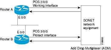
The following example shows the configuration of APS on router A and router B, and how to configure more than one protect or working interface on a router by using the aps group command. See Figure 10-1.
Figure 10-1 Basic APS Configuration
In this example, router A is configured with the working interface, and router B, is configured with the protect interface. If the working interface on router A becomes unavailable, the connection will automatically switch over to the protect interface on router B. The loopback interface is used as the interconnect. The aps group command is used even when a single protect group is configured.
On router A, which contains the working interface, use the following configuration:
Router# configure terminalRouter(config)# interface loopback 1Router(config-if)# ip address 10.10.10.10 255.0.0.0Router(config)# interface pos 2/0/0Router(config-if)# aps group 1Router(config-if)# aps working 1Router(config-if)# pos ais-shutRouter(config-if)# endOn router B, which contains the protect interface, use the following configuration:
Router# configure terminalRouter(config)# interface pos 3/0/0Router(config-if)# aps group 1Router(config-if)# aps protect 1 10.10.10.10Router(config-if)# pos ais-shutRouter(config-if)# endPOS Delay Triggers Configuration Example
The following example shows how to change POS alarm trigger delays line and alarm trigger delays path from the default of 100 milliseconds to 200 milliseconds:
!Enter global configuration mode
!
Router# configure terminal
!
! Specify the interface address
!
Router(config)# interface pos 2/1/1
!
Router(config-if)# pos delay triggers line 200
Router(config-if)# pos delay triggers path 200
SDCC Configuration Example
The following example shows how to configure an SDCC interface:
!Enter global configuration mode
!
Router# configure terminal
!
! Specify the POS interface
!
Router(config)# interface pos 5/0/1
!
! Enable SDCC on the POS interface
!
Router(config-if)# sdcc enable
!
! Exit interface configuration mode and return to
! global configuration mode
!
Router(config-if# exit
!
! Specify the SDCC interface
!
Router(config)# interface sdcc 5/0/1
!
! Specify the IP address
!
Router(config-if)# ip address 10.14.14.14. 255.0.0.0
!
! Enable the interface
!
Router(config-if)# no shutdown