Table Of Contents
Cisco RF Gateway 10 GUI User Guide
Finding Feature Information
Contents
Prerequisites for Cisco RFGW-10 GUI
Restrictions for Cisco RFGW-10 GUI
Information About Cisco RFGW-10 GUI
Recommended Browsers and Display Settings
General Instructions
Monitoring Pages
Summary
Monitor
Alarm
Configuration Pages
Redundancy
QAM
DEPI
Video
System
How to Use the Cisco RFGW-10 GUI Tool
Configuring the Cisco RFGW-10 Management Port IP Address
Configuring VRF on a FastEthernet
Configuring Management IP VRF
Enabling the IOS HTTP Server in Cisco RFGW-10 UEQAM
Configuring Cisco RFGW-10 UEQAM with a Local Username and Password
Connecting the Cisco RFGW-10 Using a Web Browser
Using Cisco RFGW-10 GUI Home Page
Troubleshooting Tips
Additional References
Related Documents
Standards
MIBs
RFCs
Technical Assistance
Feature Information for Cisco RFGW-10 GUI
Cisco RF Gateway 10 GUI User Guide
First Published: July 05, 2013
Last Updated: November 25, 2013
Cisco RF Gateway 10 (RFGW-10) GUI is a web-based interface for configuring and managing the Cisco RFGW-10 Universal Edge Quadrature Amplitude Modulation (UEQAM) device.
Finding Feature Information
Your software release may not support all the features documented in this module. For the latest feature information and caveats, see the releafse notes for your platform and software release. To find information about the features documented in this module, and to see a list of the releases in which each feature is supported, see the "Feature Information for Cisco RFGW-10 GUI" section.
Use Cisco Feature Navigator to find information about platform support and Cisco IOS, Catalyst OS, and Cisco IOS XE software image support. To access Cisco Feature Navigator, go to http://www.cisco.com/go/cfn. An account on Cisco.com is not required.
Contents
• Prerequisites for Cisco RFGW-10 GUI
•Restrictions for Cisco RFGW-10 GUI
•Information About Cisco RFGW-10 GUI
•How to Use the Cisco RFGW-10 GUI Tool
•Additional References
•Feature Information for Cisco RFGW-10 GUI
Prerequisites for Cisco RFGW-10 GUI
•HTTP server enabled Cisco RFGW-10 UEQAM device with the GUI embedded in the IOS image.
•JavaScript-enabled browser.
Restrictions for Cisco RFGW-10 GUI
•Avoid simultaneously starting the GUI client with CPU-intensive operations. This helps reduce the CPU impact on the Cisco RFGW-10 UEQAM supervisor card.
•Any CPU-intensive or high storage usage applications should be deferred to the network management system (NMS) applications.
Information About Cisco RFGW-10 GUI
The Cisco RFGW-10 GUI is an embedded web application residing in the Cisco RFGW-10 UEQAM chassis. The GUI image (RFGW_GUI.tar) is embedded in the Cisco RFGW-10 IOS-XE image and is installed as part of the IOS-XE image installation. There are no configuration steps for installing this application.
Following are some of its important features:
•An intuitive interface that combines easy navigation with point-and-click provisioning of services, thereby reducing the complexity of configuring services and features.
•Support to manage the Cisco RFGW-10 system.
•A monitoring interface with flexible choice of statistics and graphs.
•Bulk configuration in a single attempt.
You can access this application through a web browser that has IP connectivity to the chassis. For information on how to access the application, see the "How to Use the Cisco RFGW-10 GUI Tool" section.
Recommended Browsers and Display Settings
We recommend the following browsers and display settings:
Client Platform
|
Web Browser
|
Display Settings
|
Windows XP
or Windows 7
|
Mozilla FireFox version 10.x and above
Internet Explorer version 6.0 and above
Opera version 10x and above
|
1024x768 or above
|
Note The Cisco RFGW-10 GUI is best viewed on Mozilla Firefox version 10.x or above.
General Instructions
These are some general instructions and information:
•Click AddRow to add multiple rows.
•A new row added in a page or pane appears in green color.
•A row appears in yellow color when it is edited.
•An invalid entry appears in red color.
•Click Select All to check the Delete checkbox for all entries. Click DeSelect All to uncheck the Delete checkbox for all entries.
•Click the Refresh button to refresh data on the current page.
•Check the Apply All checkbox at the bottom of a page or pane to apply the value entered in a current field to all entries in that page or pane. For example, in the DS384 3 Video Qam Channel Configuration pane, select the desired value from Cable Mode in one row (row changes to yellow color) and check the Cable Mode Apply All checkbox to apply the selected value to all Cable Mode fields in the pane. The checkbox is disabled when multiple rows are in edit mode.
Note You must check the Apply All checkbox while applying the changes.
•A QAM channel configuration cannot be edited after it is assigned to a QAM replication group.
•Every page and pane with configurable fields have validation embedded in them. A common javascript validation occurs and appropriate messages are displayed in a popup window.
•A confirmation message is displayed each time you click the Delete button.
•Use the navigation icons (|<<, <<, >>, >>|) or check the Show All checkbox at the top of a pane to view data presented across multiple pages.
•Click a header field (hyperlink appears on mouse-over) to sort the content either in ascending or descending order.
•Some pages or panes show the current LED status. See the relevant hardware documentation to interpret the LED status.
•Action buttons such as Apply, Clear New, Delete are enabled only after the corresponding action like entering data in the fields or selecting a row is performed. Until then they are disabled.
•A blue color Loading timer icon appears in the main configuration pages to indicate that data is being loaded.
Figure 1 Loading Icon
Monitoring Pages
The Cisco RFGW-10 GUI application includes the following monitoring pages:
•Summary
•Monitor
•Alarm
Summary
The summary page provides a snapshot of the Cisco RFGW-10 system with the following information:
•Chassis Information—View chassis related information such as Redundancy, Alarms, SUP GbE Inputs, and SUP GbE Input Statistics..
•Line Card Bandwidth Information—View line card related information such as redundancy, GbE bandwidth, QAM bandwidth, QAM bandwidth utilization details for the selected line card.
•Line Card Session Information—View DEPI or Video session information for the selected line card.
Chassis
Use this page to view chassis related information.
Figure 2 Chassis Page
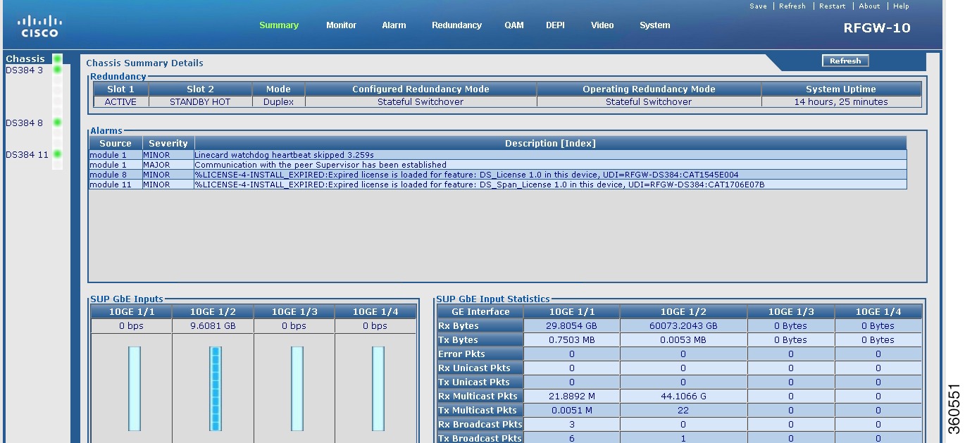
Table 1 Chassis Page Field Description
Field
|
Description
|
Redundancy
|
Slot 1
|
State of the Supervisor card in slot 1.
|
Slot 2
|
State of the Supervisor card in slot 2.
|
Mode
|
Mode in which the system is operating.
|
Configured Redundancy Mode
|
Redundancy mode configured on the system.
|
Operating Redundancy Mode
|
Current redundancy mode of the system.
|
System Uptime
|
Time duration of how long the system has been alive.
|
Alarms
|
Source
|
Source module where the alarm is generated.
|
Severity
|
Severity classification of the alarm.
|
Description [Index]
|
Alarm description.
|
SUP GbE Inputs
Shows bandwidth of each Gigabit Ethernet port and depicts bandwidth both graphically (bar graph, where one bar indicates 10 per cent of bandwidth) and numerically.
Click a GbE to view its IP address configuration and performance report.
|
SUP GbE Input Statistics
Shows information about each input GbE port.
|
Rx Bytes
|
Number of input bytes.
|
Tx Bytes
|
Number of output bytes.
|
Error Pkts
|
Total error count.
|
Rx Unicast Pkts
|
Number of input unicast packets.
|
Tx Unicast Pkts
|
Number of output unicast packets.
|
Rx Multicast Pkts
|
Number of input multicast packets.
|
Tx Multicast Pkts
|
Number of output multicast packets.
|
Rx Broadcast Pkts
|
Number of input broadcast packets.
|
Tx Broadcast Pkts
|
Number of output broadcast packets.
|
Note Only the active Supervisor card GbE are listed.
|
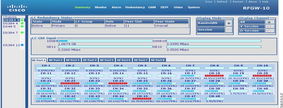
Line Card slot
Click a line card (DS384 slot or DS48 slot) to view its information.
Figure 3 Line Card Bandwidth Information Page
Figure 4 Line Card Bandwidth Video Session Information Page
Figure 5 Line Card Session Information Page
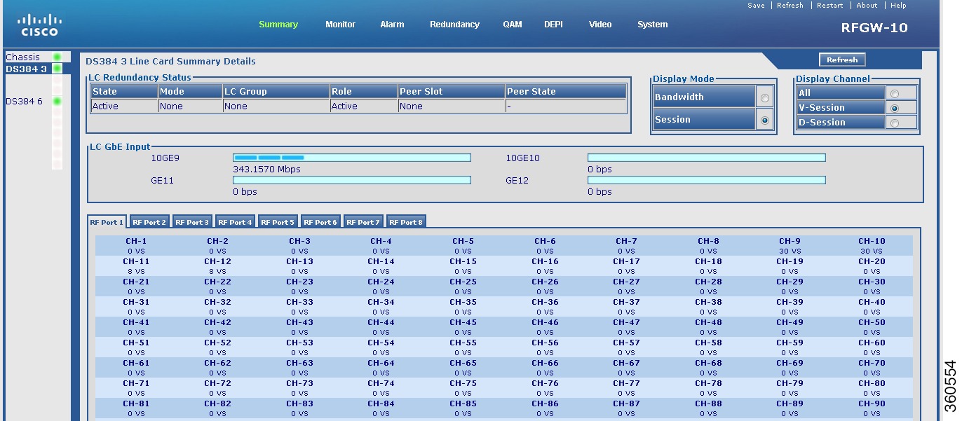
Table 2 Line Card slot Page Field Description
Field
|
Description
|
LC Redundancy Status
|
State
|
Active or standby.
|
Mode
|
Redundancy mode of the line card (Primary or Secondary).
|
LC Group
|
Line card group number.
|
Role
|
Current state of the line card.
|
Peer Slot
|
Slot number where the peer line card resides in the chassis.
|
Peer State
|
Current state of the peer line card.
|
LC GbE Input
|
Ten GigabitEthernet interfaces
|
Click a 10GE to view its IP address configuration and performance report.
Note Not suppported on the Cisco DS-48 line card.
|
GigabitEthernet interfaces
|
Click a GE to view its IP address configuration and performance report.
|
Display Mode
|
Select Bandwidth to view bandwidth usage details.
•For the Cisco DS-384 line card (eight RF ports) and Cisco DS-48 line card (twelve RF ports), the following bandwidth details are displayed for each channel on an RF port:
–Bandwidth used on the channel (graphical representation; each bar indicates 10 per cent of bandwidth).
–Bandwidth used on the channel (numerical representation).
–Bandwidth utiliation percentage.
Click on channel to view its detailed bandwidth information.
|
Select Session to view session count information for each channel on an RF port on the line card.
•For the Cisco DS-384 line card (eight RF ports), the following session details are displayed for each channel on an RF port:
–Number of video sessions.
–Number of DEPI sessions.
Click on channel to view its detailed session information.
•For the Cisco DS-48 line card (twelve RF ports), the DEPI session details are displayed for each channel on an RF port.
A QAM channel is identified as:
•Pilot QAM—Using a green color asterisk. Place the cursor on the channel to view its QRG information.
•Replicate QAM—Using a blue color asterisk. Place the cursor on the channel to view its QRG and pilot QAM information.
|
Display Channel
|
All
|
Select All to view Bandwidth or Session (DEPI/VIDEO) information for all channels on selected RF ports on the line card.
Select Display Mode as Bandwidth and Display Channel as All to view QAM channel bandwidth information.
Select Display Mode as Session and Display Channel as All to view QAM channel session (DEPI/VIDEO) information.
|
V-Session
|
Select V-Session to view Bandwidth or Session (VIDEO) information for all channels on selected RF ports on the line card.
When the Display Mode is Session and Display Channel is V-Session, the number of video sessions configured on each QAM channel for each RF port is displayed.
When the Display Mode is Bandwidth and Display Channel is V-Session, the bandwidth used on the video mode QAM channel is displayed using the grey color graphical representation.
|
D-Session
|
Select D-Session to view Bandwidth or Session (DEPI) information for all channels on selected RF ports on the line card.
When the Display Mode is Session and Display Channel is D-Session, the number of DEPI sessions configured on each QAM channel for each RF port is displayed.
When the Display Mode is Bandwidth and Display Channel is D-Session, the bandwidth used on the DEPI mode QAM channel is displayed using the grey color graphical representation.
|
Click a QAM channel to view its detailed session information.
•Blue color—Represents bandwidth (graphical).
•Grey color—Represents bandwidth for selected session type.
•Red color—Represents bandwidth reaching 100 per cent.
•VS—Represents video sessions.
•DS—Represents DEPI sessions.
|
Monitor
Use the tree-based navigation on the Monitor page to do this:
•Monitor—View Supervisor card, TCC card, or line card session count information.
•Inventory—View chassis, Supervisor card, line card, TCC card, power supply and fan tray inventory information.
•Environment—View environment information of the chassis.
•Performance—View Supervisor and line card input and output port performance information.
•TCC Cards—View DTI client and client port status information for the TCC cards.
•DEPI—View chassis and line card DEPI session information for selected line card, RF port and QAM channel.
•Video—View video sessions and packets information.
•CLI Output—Use the show commands and view output.
Monitor
Use this page to view hardware modules location, device information and session count information.
Figure 6 Monitor Page
Table 3 Monitor Page Field Description
Field
|
Description
|
SUP and LC Information
|
SUP Cards
|
Number of Supervisor cards installed in the chassis and its slot location.
|
DS48 LC Cards
|
Number of Cisco DS-48 line cards installed in the chassis and its slot location.
|
DS384 LC Cards
|
Number of Cisco DS-384 line cards installed in the chassis and its slot location.
|
TCC Cards
|
Number of TCC cards installed in the chassis and its slot location.
|
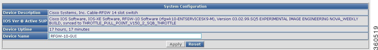
System Information
|
Device Description
|
Device information.
|
IOS Ver @ Active SUP
|
Cisco IOS-XE version running on the active Supervisor card.
|
Device Uptime
|
Time duration of how long the device has been alive.
|
Device Name
|
Name of the device.
|
DEPI Global Session Information
|
Total Manual DEPI Session
|
Total number of manual DEPI sessions on the chassis.
|
Total L2TP DEPI Session
|
Total number of L2TP DEPI sessions on the chassis.
|
Total DEPI Session
|
Total number of DEPI sessions on the chassis.
|
Video Global Session Information
|
Total Unicast Session
|
Total number of unicast sessions on the chassis.
|
Total Multicast Session
|
Total number of multicast sessions on the chassis.
|
Total Video Session
|
Total number of video sessions on the chassis.
|
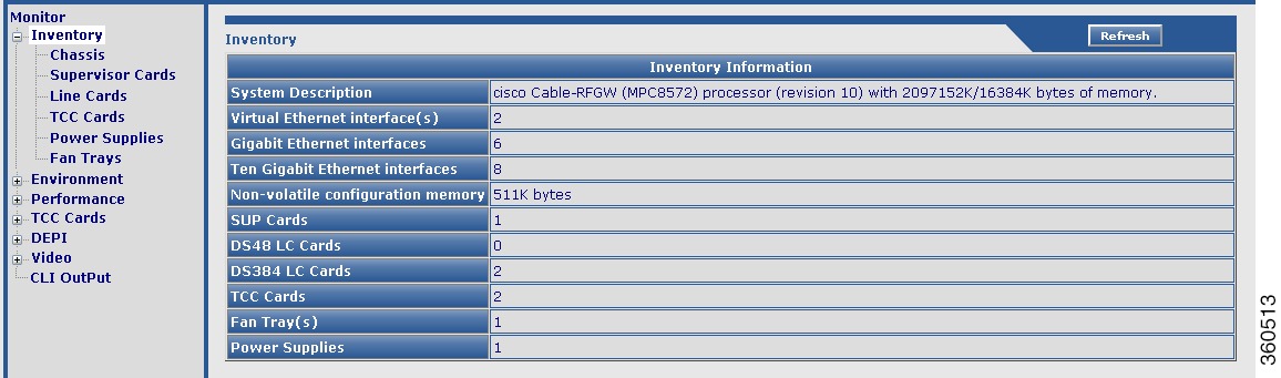
Inventory
Use this page to view the system inventory information.
Figure 7 Inventory Page
Table 4 Inventory Page Field Description
Field
|
Description
|
Inventory Information
|
System Description
|
Brief description of the chassis.
|
Virtual Ethernet interface(s)
|
Total number of virtual Ethernet interfaces configured in the chassis.
|
Gigabit Ethernet interfaces
|
Total number of GigabitEthernet interfaces configured in the chassis.
|
Ten Gigabit Ethernet interfaces
|
Total number of Ten GigabitEthernet interfaces configured in the chassis.
|
Non-volatile configuration memory
|
Non-volatile configuration memory capacity in bytes.
|
SUP Cards
|
Total number of Supervisor cards installed in the chassis.
|
DS48 LC Cards
|
Total number of Cisco DS-48 line cards installed in the chassis.
|
DS384 LC Cards
|
Total number of Cisco DS-384 line cards installed in the chassis.
|
TCC Cards
|
Total number of TCC cards installed in the chassis.
|
Fan Tray(s)
|
Total number of fan trays installed in the chassis.
|
Power Supplies
|
Total number of power supplies used in the chassis.
|
Use the tree-based navigation to do the following:
•Chassis—View chassis inventory related information.
•Supervisor Cards—View supervisor card inventory related information.
•Line Cards—View line card inventory related information.
•TCC Cards—View TCC card inventory related information.
•Power Supplies—View power supply inventory related information.
•Fan Trays—View fan tray inventory related information.
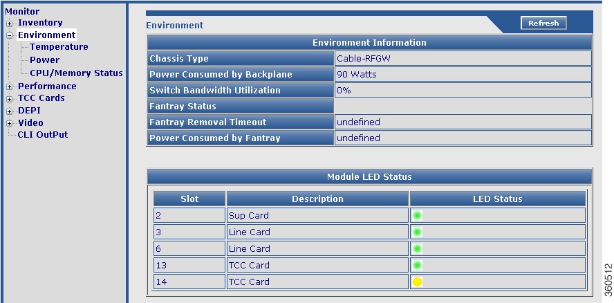
Environment
Use this page to monitor and report the environmental conditions important for the overall health of Cisco RFGW-10 UEQAM.
Figure 8 Environment Page
Table 5 Environment Page Field Description
Field
|
Description
|
Environment Information
|
Chassis Type
|
Chassis type description.
|
Power Consumed by Backplane
|
Power (in Watts) consumed by the backplane.
|
Switch Bandwidth Utilization
|
Bandwidth utilization by the switch.
|
Fantray Status
|
Current fan tray status.
|
Fantray Removal Timeout
|
The time interval by when you must install a fan tray must be installed or replace it in the chassis during an OIR to avoid automatic shut down. The maximum time is 4 minutes, that is 240 seconds.
|
Power Consumed by Fantray
|
Power (in Watts) consumed by the fan tray.
|
Module LED Status
|
Slot
|
Slot location where the hardware module resides on the chassis.
|
Description
|
Name of the hardware module.
|
LED Status
|
Current LED status.
|
Use the tree-based navigation to do the following:
•Temperature—View environment temperature related information. The following colors are used to indicate temperature status:
–Green—Active; when the current temperature is less than the threshold temperature.
–Blue—Warning; when the current temperature is greater than or equal to the threshold temperature.
–Red—Critical; when the current temperature is greater than or equal to the critical temperature.
–White—Shutdown; when the current temperature is greater than or equal to the shutdown temperature.
Table 6 Temperature Page Field Description
Field
|
Description
|
Environment Temperatures
|
Module
|
Hardware component identifier.
|
Sensor Name
|
Sensor name.
|
Temperature
|
Current temperature of the chassis.
|
Threshold Temp
|
Recommended threshold temperature.
|
Critical Temp
|
Maximum temperature that indicates critical threshold.
|
Shutdown Temp
|
Temperature at which the chassis shuts down.
|
Status
|
Current status.
|
•Power—View environment power related information.
Table 7 Power Page Field Description
Field
|
Description
|
Power
|
Power supplies needed by system
|
Number of power supplies required for normal functioning of the chassis.
|
Power supplies currently available
|
Number of power supplies currently used by the chassis.
|
Power consumed by Backplane
|
Power (in Watts) consumed by the backplane.
|
Power consumed by Fantray
|
Power (in Watts) consumed by the fantray.
|
Power Supply Detail
|
Power Supply
|
Power supply identifier.
|
Model No
|
Model information of the power supply.
|
Type
|
Type of power supply.
|
Status
|
Current status of the power supply.
|
Fan Sensor
|
Current status of the fan sensor.
|
Inline Status
|
Inline power status.
|
•CPU/Memory Status—View CPU and memory utilization related information.
Table 8 CPU/Memory Status Page Field Description
Field
|
Description
|
CPU Utilization
|
Core Details for Core 0 and Core 1
|
For 5 Seconds
|
CPU utilization percentage for 5 seconds.
|
For 1 Minute
|
CPU utilization percentage for 1 minute.
|
For 5 Minutes
|
CPU utilization percentage for 5 minutes.
|
Memory Utilization
|
Memory Details for System, Process and Configuration
|
Total(K)
|
Total memory available for the system, process and configuration.
|
Used(K)
|
Memory used for the system, process and configuration.
|
Free(K)
|
Memory unused or available for the system, process and configuration.
|
Util %
|
Memory utilization percentage for the system, process and configuration.
|
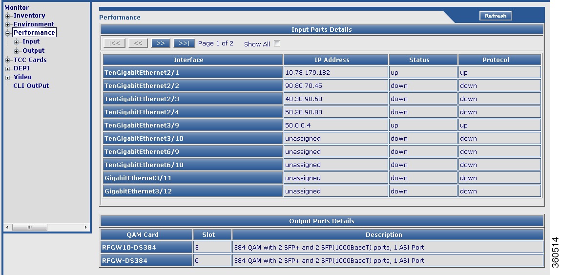
Performance
Use this page to view all the GigabitEthernet and Ten GigabitEthernet performances categorized as Input and the performance information of each QAM channel categorized as Output.
Figure 9 Performance Page
Table 9 Performance Page Field Description
Field
|
Description
|
Input Ports Details
|
Interface
|
Interface type and identifier.
|
IP Address
|
Enter the interface IP address.
|
Status
|
Current input interface status.
|
Protocol
|
Protocol status of the input interface.
|
Output Ports Details
|
QAM Card
|
QAM line card name.
|
Slot
|
Slot location on the chassis where the line card resides.
|
Description
|
Brief description of the line card composition.
|
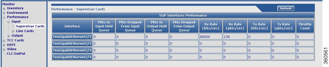
Use the tree-based navigation to do the following:
•Input—View Ethernet interface input port related information.
–Supervisor Cards—View supervisor Ethernet interface performation information.
Figure 10 Input Supervisor Cards Page
–Line Cards—View all line card Ethernet interface performance information:
a. Packets In Input Hold Queue
b. Packets Dropped From Input Queue
c. Packets In Output Hold Queue
d. Packets Dropped From Output Queue
e. Receive Rate (bits/sec)
f. Receive Rate (Packets/sec)
g. Transmit Rate (bits/sec)
h. Transmit Rate (Packets/sec)
i. Throttle Count
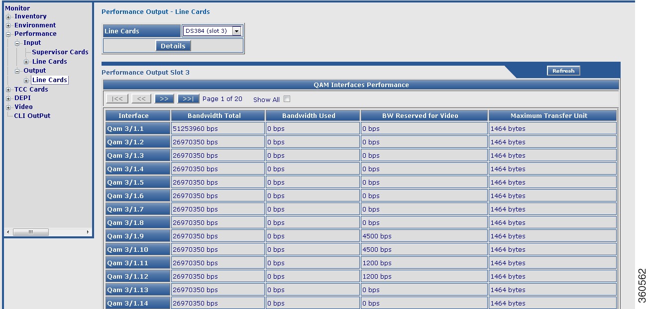
•Output—Use the tree-based navigation to view QAM channel performance information for the selected line card or RF port.
Figure 11 Output Line Cards Page
–Line Cards—View all line card QAM channel bandwidth information:
a. Total bandwidth
b. Used bandwidth
c. Bandwidth reserved for Video
d. Maximum transfer unit
–DS384/DS48 slot—View selected line card QAM interface performance information:
a. Packets In Input Hold Queue
b. Packets Dropped From Input Queue
c. Packets In Output Hold Queue
d. Packets Dropped From Output Queue
e. Receive Rate (bits/sec)
f. Receive Rate (Packets/sec)
g. Transmit Rate (bits/sec)
h. Transmit Rate (Packets/sec)
i. Throttle Count
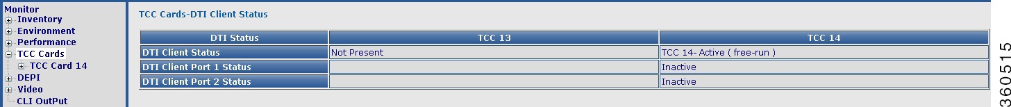
TCC Cards
Use this page to view TCC card status information.
Figure 12 TCC Cards Page
Table 10 TCC Cards Page Field Description
Field
|
Description
|
TCC Cards-DTI Client Status
|
DTI Status (TCC 13 and TCC 14)
|
DTI Client Status
|
TCC card status information.
|
DTI Client Port 1 Status
|
Active or inactive.
|
DTI Client Port 2 Status
|
Active or inactive.
|
Use the tree-based navigation to do the following:
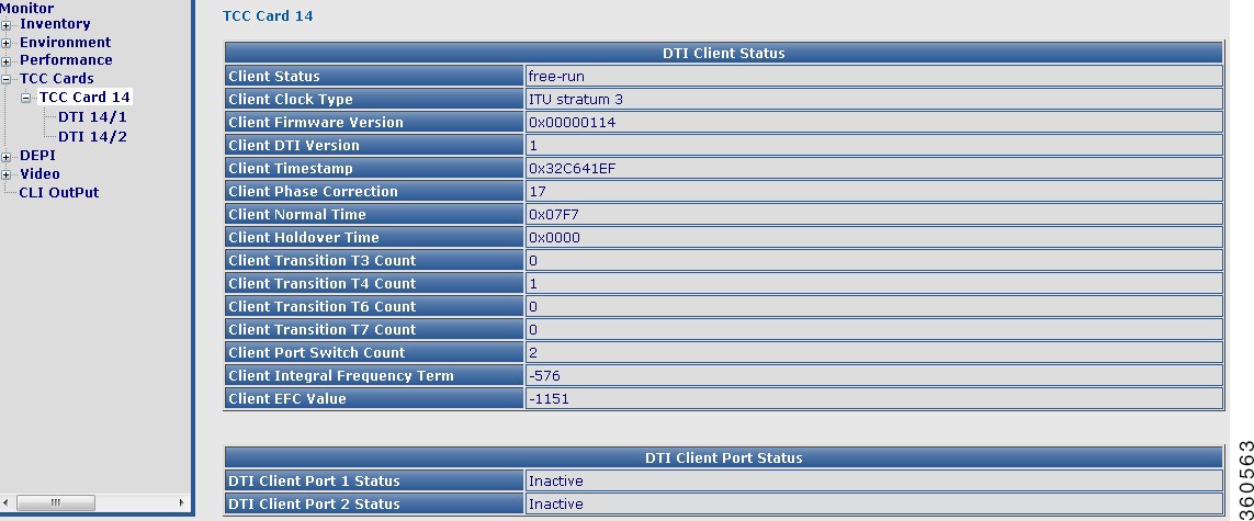
•TCC Card slot—View DTI client and port status information.
Figure 13 TCC Card slot Page
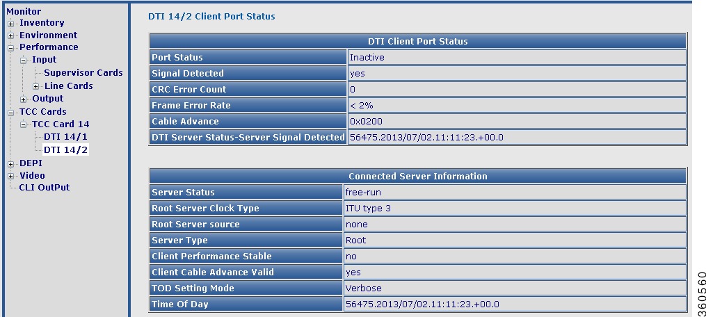
•DTI slot/port—View DTI client port status and connected server information.
Figure 14 DTI slot/port Page
DEPI
Use this page to view chassis and line card DEPI session count and session information.
Figure 15 DEPI Page
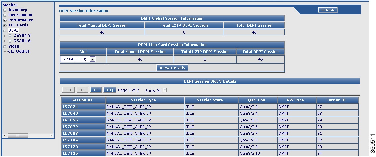
Table 11 DEPI Page Field Description
Field
|
Description
|
DEPI Global Session Information
|
Total Manual DEPI Session
|
Total number of manual DEPI sessions on the chassis.
|
Total L2TP DEPI Session
|
Total number of L2TP DEPI sessions on the chassis.
|
Total DEPI Session
|
Total number of DEPI sessions on the chassis.
|
DEPI Line Card Session Information
|
Slot
|
Slot where the line card resides. Use the drop-down list to choose a line card and click View Details to view its DEPI session information.
|
Total Manual DEPI Session
|
Total number of manual DEPI sessions on the line card.
|
Total L2TP DEPI Session
|
Total number of L2TP DEPI sessions on the line card.
|
Total DEPI Session
|
Total number of DEPI sessions on the line card.
|
DEPI Session Slot slot Details
|
Session ID
|
DEPI session ID. Click a session ID to view its DEPI session information.
|
Session Type
|
DEPI session type.
|
Session State
|
DEPI session current state.
|
QAM Chn
|
QAM channel information for the DEPI session.
|
PW Type
|
DEPI mode for the DEPI session.
|
Carrier ID
|
Carrier ID for the DEPI session.
|
Use the tree-based navigation to view the line card, RF port, or channel level specific DEPI information.
|
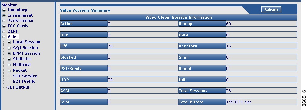
Video
Use this page to view all video session summary information.
Figure 16 Video Page
Table 12 Video Page Field Description
Field
|
Description
|
Video Sessions Summary
|
Active
|
Total number of active video sessions on the chassis.
|
Idle
|
Total number of idle video sessions on the chassis.
|
Off
|
Total number of sessions in "OFF" state.
|
Blocked
|
Total number of sessions in "Blocked" state.
|
PSI-Ready
|
Total number of video sessions that are PSI-ready.
|
UDP
|
Total number of UDP sessions on the chassis.
|
ASM
|
Total number of ASM sessions on the chassis.
|
SSM
|
Total number of SSM sessions on the chassis.
|
Remap
|
Total number of video sessions configured as Remap.
|
Data
|
Total number of video sessions configured as Data.
|
PassThru
|
Total number of video sessions configured as PassThru.
|
Shell
|
Total number of video shell sessions.
|
Bound
|
Total number of video bound sessions.
|
Init
|
Total number of sessions in "init" state.
|
Total Sessions
|
Total number of video sessions on the chassis.
|
Total Bitrate
|
Bitrate value for the chassis (in bps).
|
Local Session
Use this page to view chassis and line card video local session information.
Figure 17 Local Session Page
Table 13 Local Session Page Field Description
Field
|
Description
|
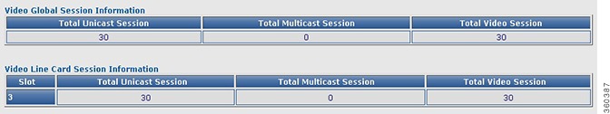
Video Global Session Information
|
Total Unicast Session
|
Total number of unicast video local sessions on the chassis.
|
Total Multicast Session
|
Total number of multicast video local sessions on the chassis.
|
Total Video Session
|
Total number of video local sessions on the chassis.
|
Video Line Card Session Information
|
Slot
|
Use the drop-down list to choose a slot and click View Details button to view its video local session details.
|
Total Unicast Session
|
Total number of unicast video local sessions on the selected line card.
|
Total Multicast Session
|
Total number of multicast video local sessions on the selected line card.
|
Total Video Session
|
Total number of video local sessions on the selected line card.
|
Video Session Slot All Details
|
Session ID
|
Click a session ID to view its detailed video session information.
|
QAM Port
|
QAM port information.
|
Stream Type
|
Video session stream type.
|
Session Type
|
Video session type.
|
Ip Address
|
Video session IP address.
|
UDP Port
|
UDP port number.
|
Out Pgm
|
Single ProgramTransport Stream (SPTS) or Multiple ProgramTransport Stream (MPTS) program number.
|
Input Bitrate
|
Actual bitrate measured on the input.
|
Input State
|
State on the input.
|
Output State
|
State on the output.
|
PSI Rdy
|
PSI ready state.
|
Ctrl State
|
Controller state.
|
Note Use the tree-based navigation available at the line card, RF Port and QAM channel level to view configured local session information.
|
GQI Session
Use this page to view chassis and line card video GQI session information.
Table 14 GQI Session Page Field Description
Field
|
Description
|
Video Global GQI Session Information
|
Total Unicast Session
|
Total number of unicast video GQI sessions on the chassis.
|
Total Multicast Session
|
Total number of multicast video GQI sessions on the chassis.
|
Total Video Session
|
Total number of video GQI sessions on the chassis.
|
Video Line Card GQI Session Information
|
Slot
|
Use the drop-down list to choose a slot and click View Details button to view its video GQI session details.
|
Total Unicast Session
|
Total number of unicast video GQI sessions on the selected line card.
|
Total Multicast Session
|
Total number of multicast video GQI sessions on the selected line card.
|
Total Video Session
|
Total number of video GQI sessions on the selected line card.
|
Video GQI Session Slot slot Details
|
GQI Session ID
|
Click a GQI session ID to view its detailed video session information.
|
QAM Carrier
|
QAM carrier information.
|
QP Id
|
QAM partition identifier.
|
SCM Id
|
Session control manager identifier.
|
Stream Type
|
Video session stream type.
|
Session Type
|
Video session type.
|
Ip Address
|
Video session IP address.
|
UDP Port
|
UDP port number.
|
Out Pgm
|
Single ProgramTransport Stream (SPTS) or Multiple ProgramTransport Stream (MPTS) program number.
|
Input Bitrate
|
Actual bitrate measured on the input.
|
Input State
|
State on the input.
|
Output State
|
State on the output.
|
PSI Rdy
|
PSI ready state.
|
Encrypt
|
Encryption status and type.
|
Note Use the tree-based navigation available at the line card, RF Port and QAM channel level to view configured GQI session information.
|
ERMI Session
Use this page to view chassis and line card edge resource manager interface (ERMI) session count information.
Table 15 ERMI Session Page Field Description
Field
|
Description
|
Video Global ERMI Session Information
|
Total Unicast Session
|
Total number of unicast video ERMI sessions on the chassis.
|
Total Multicast Session
|
Total number of multicast video ERMI sessions on the chassis.
|
Total Video Session
|
Total number of video ERMI sessions on the chassis.
|
Video Line Card ERMI Session Information
|
Slot
|
Use the drop-down list to choose a slot and click View Details button to view its video ERMI session details.
|
Total Unicast Session
|
Total number of unicast video ERMI sessions on the selected line card.
|
Total Multicast Session
|
Total number of multicast video ERMI sessions on the selected line card.
|
Total Video Session
|
Total number of video ERMI sessions on the selected line card.
|
Video ERMI Session Slot slot Details
|
ERMI Session ID
|
Click an ERMI session ID to view its detailed video session information.
|
QAM Carrier
|
QAM carrier information.
|
QP Id
|
QAM partition identifier.
|
SCM Id
|
Session control manager identifier.
|
Stream Type
|
Video session stream type.
|
Session Type
|
Video session type.
|
Ip Address
|
Video session IP address.
|
UDP Port
|
UDP port number.
|
Out Pgm
|
Single ProgramTransport Stream (SPTS) or Multiple ProgramTransport Stream (MPTS) program number.
|
Input Bitrate
|
Actual bitrate measured on the input.
|
Input State
|
State on the input.
|
Output State
|
State on the output.
|
PSI Rdy
|
PSI ready state.
|
Session Grp
|
Session group identifier.
|
Note Use the tree-based navigation available at the line card, RF Port and QAM channel level to view configured ERMI session information.
|
Use the tree-based navigation to do the following:
•DS384 slot—View line card ERMI session information.
•ERRP Statistics—View ERMI ERRP statistics information.
•ERRP Server—View ERMI ERRP server information.
•ERRP Server Resources—View ERMI ERRP server resources information.
•RTSP Statistics—View ERMI RTSP statistics information.
•RTSP Server—View ERMI RTSP server information.
Statistics
Use this page to view all line card video packet statistics summary information.
Table 16 Statistics Page Field Description
Field
|
Description
|
Video Packets Statistics
|
Slot Id
|
Slot location where the line card resides on the chassis.
|
LBG Id
|
Load balancing group identifier.
|
Multicast Groups
|
Number of multicast groups.
|
Multicast Sessions
|
Number of multicast sessions.
|
Unicast Sessions
|
Number of unicast sessions.
|
Multicast DS Packets
|
Number of multicast downstream packets.
|
Unicast DS Packets
|
Number of unicast downstream packets.
|
Use the tree-based navigation to do the following:
•DS384 slot—View line card video packet statistics brief and detailed information.
Multicast
Use this page to view all line card or selected line card video route multicast information.
Table 17 Multicast Page Field Description
Field
|
Description
|
Video Route Multicast
|
Line Cards
|
Use the drop-down list to select a line card to view its video route multicast information or All to view a summary of all routes configured on the line card and click Details.
|
Video Route Multicast Slot slot Information
|
Source
|
Multicast source IP address.
|
Group
|
Multicast group IP address.
|
Rx-Interface
|
Input interface (GbE/10GbE).
|
Tx-slot/LBG
|
Output slot and load balancing group.
|
Sessions
|
Total number of sessions.
|
Use the tree-based navigation to do the following:
•Up Link—View the video multicast uplink summary information.
Table 18 Up Link Page Field Description
Field
|
Description
|
Video Multicast Uplink
|
Uplink Interface
|
Uplink interface (GbE/10GbE).
|
Status
|
Current status of the uplink interface.
|
Allocated Streams
|
Total number of streams allocated for the uplink interface.
|
Maximum Bandwidth
|
Maximum bandwidth available for the uplink interface.
|
Allocated Bandwidth
|
Maximum bandwidth allocated for the uplink interface.
|
Backup Interface
|
Backup uplink interface.
|
Backup Activated
|
Backup activation status.
|
Packet
Use this page to view global video insertion packet information.
Table 19 Packet Page Field Description
Field
|
Description
|
Global Video Packets Information
|
Packet Stream ID
|
Packet stream identifiers of the video packets.
|
Interface
|
QAM channel or QAM subinterface.
|
Version
|
Video packet version.
|
Times Repeat
|
Packets repetition state such as continuous.
|
Actual Repeated
|
Number of times the packets are repeated.
|
Insert Rate (bps)
|
Rate at which packets are inserted.
|
Number of Pkts Inserted
|
Number of packets inserted.
|
State
|
Status of the packets (on or off).
|
Use the tree-based navigation to view this information at a line card, RF port, or chassis level.
|
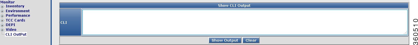
CLI Output
Use the CLI Output page to use the show commands.
Figure 18 CLI Output Page
Enter the show command in the CLI field and click Show Output to view the command output, or Clear to abort.
Alarm
Use the tree-based navigation on the Alarm page to do the following:
•Alarms—Use this page to view all alarms logged in the system.
•Severe Logs—Use this page to view top 20 severe logs displayed based on the highest severity level.
•Logging—Use this page to view common logging information.
•All Logs—Use this page to view all logs.
Alarms
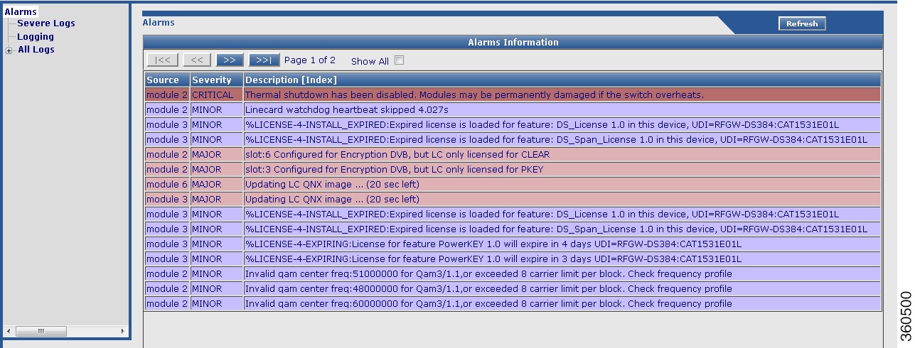
Use this page to view all alarms logged in the system.
Figure 19 Alarms Page
Table 20 Alarms Page Field Description
Field
|
Description
|
Alarms
|
Source
|
Source module where the alarm is generated.
|
Severity
|
Severity classification of the alarm.
|
Description [Index]
|
Alarm description.
|
Note:
•Critical—Alarms with severity as critical are displayed in red color.
•MAJOR—Alarms with severity as major are displayed in orange color.
•Minor—Alarms with severity as minor are displayed in blue color.
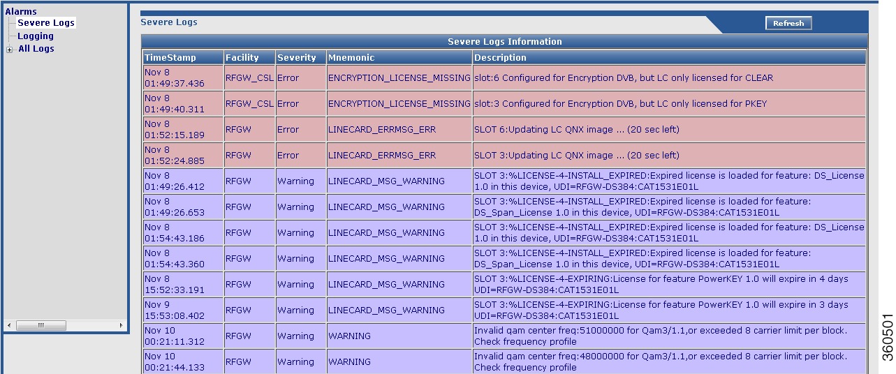
Severe Logs
Use this page to view the top 20 severe logs in the system.
Figure 20 Severe Logs Page
Table 21 Severe Logs Page Field Description
Field
|
Description
|
Severe Logs
|
TimeStamp
|
Timestamp for the log.
|
Facility
|
Module for which the log was generated.
|
Severity
|
Severity of the log.
|
Mnemonic
|
Label for the class of log.
|
Description
|
Log description.
|
Note:
The logs are displayed in order of severity:
1. emergency(0)
2. alert(1)
3. critical(2)
4. error(3)
5. warning(4)
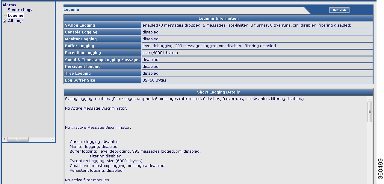
Logging
Use this page to view logging information and logging details.
Figure 21 Logging Page
Table 22 Logging Page Field Description
Field
|
Description
|
Logging Information
|
Syslog Logging
|
Information about syslog message logging.
|
Console Logging
|
Information about console message logging.
|
Monitor Logging
|
Information about monitor message logging.
|
Buffer Logging
|
Information about buffer message logging.
|
Exception Logging
|
Information about exception message logging.
|
Count & Timestamp Logging Messages
|
Information about count and timestamp message logging.
|
Persistent logging
|
Information about persistent message logging.
|
Trap Logging
|
Information about trap message logging.
|
Log Buffer Size
|
Log buffer size.
|
Show Logging Details
Displays the show logging command output.
|
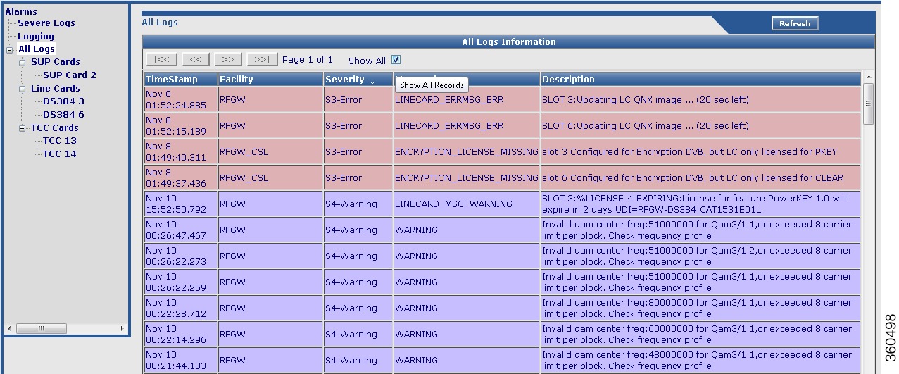
All Logs
Use this page to view all the logs in the system.
Figure 22 All Logs Page
Table 23 All Logs Page Field Description
Field
|
Description
|
TimeStamp
|
Timestamp for the log.
|
Facility
|
Module for which the alarm was generated.
|
Severity
|
Severity of the alarm.
|
Mnemonic
|
Label for the class of alarm.
|
Description
|
Alarm description.
|
Use the tree-based navigation to view the following:
•SUP Cards—Use this page to view supevisor card specific logs.
•Line Cards—Use this page to view line card specific logs.
•TCC Cards—Use this page to view TCC card specific logs.
Configuration Pages
The Cisco RFGW-10 GUI application includes the following configuration pages:
•Redundancy
•QAM
•DEPI
•Video
•System
Redundancy
Use the tree-based navigation on the Redundancy page to do this:
•Redundancy—View chassis redundancy information, edit redundancy mode, and change the redundancy main-CPU auto sync configuration.
•Supervisor cards—View supervisor card redundancy information.
•Line Cards—Create and manage line card redundancy groups and view line card redundancy information.
•TCC Cards—View TCC card redundancy information.
•Switchover—Manage hardware component switchover and reload.
Redundancy
Use this page to view chassis redundancy information, edit redundancy mode, and change the redundancy main-CPU auto sync configuration.
Figure 23 Redundancy Page
Table 24 Redundancy Page Field Description
Field
|
Description
|
Redundant System Information
|
Available system uptime
|
Time duration of how long the system has been alive.
|
Switchovers System Experienced
|
Total number of switchovers on the system.
|
Standby Failures
|
Total number of standby Supervisor failures.
|
Last Switchover Reason
|
Reason why the last switchover occured.
|
Hardware Mode
|
Mode in which the system is operating.
|
Configured Redundancy Mode
|
Redundancy mode configured on the system.
|
Operating Redundancy Mode
|
Current redundancy mode of the system.
|
Maintenance Mode
|
Maintenance mode.
|
Communications
|
Communication mode.
|
Redundancy Mode Configuration
|
Redundancy Mode
|
Redundancy mode of the chassis. Use the drop-down list to choose a mode for the chassis.
|
Click Apply to accept changes and Reset to abort.
|
Redundancy Main-CPU Auto Sync Configuration
|
Sync Element
|
Check the checkbox against the desired element to auto synchronize with the Main-CPU configuration.
Click Apply to accept changes and Reset to abort.
|
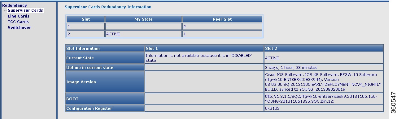
Supervisor cards
Use this page to view Supervisor card redundancy information.
Figure 24 Supervisor Cards Page
Table 25 Supervisor Cards Page Field Description
Field
|
Description
|
Supervisor Cards Redundancy Information
|
Slot
|
Slot number where the Supervisor card resides in the chassis.
|
My State
|
Current state of the Supervisor card.
|
Peer Slot
|
Slot number of the peer Supervisor card.
|
Slot Information (Slot 1/Slot 2)
|
Following slot information are listed for the Supervisor cards in slot 1 and slot 2:
•Current State—Current state of the Supervisor card.
•Uptime in current state—Time duration of how long the card has been up in its current state.
•Image Version—Software image version information.
•BOOT—Boot path.
•Configuration Register—Assigned configuration register value of the Supervisor card.
|
Line Cards
Use this page to manage redundancy groups and view line card redundancy information.
Figure 25 Line Cards Page
Table 26 Line Cards Page Field Description
Field
|
Description
|
LineCard Redundancy Group Config
|
Group ID
|
Line card group identifier. Valid value is 0 or 1.
|
Red Class
|
Use the drop-down list to assign a class to the group. Valid value is 1:N or 1:1.
|
Primary Slot
|
Primary members of the line card redundancy group. Enter line card slot number seperated by a comma to add or remove from the group. The valid values are 3 to 10.
|
Secondary Slot
|
Secondary members of the line card redundancy group. The valid value is 11 or 12.
|
CardType
|
Use the drop-down list to reserve a card type for the redundancy group.
|
Revertive Time
|
Enable revertive switchover and enter the timeout interval (in seconds) for the revert to occur. The valid range is from 10 to 86400 or NON-revertive.
|
Description
|
Enter the line card group description.
|
Delete
|
Check the checkbox and click Delete to delete a line card group entry.
|
Click AddRow to add a new entry, Apply to accept changes, or Reset to abort.
|
Redundancy Line Cards Information
|
Slot
|
Slot number where the line card resides in the chassis.
|
SubSlot
|
Subslot number of the line card.
|
LC Group
|
Line card group number.
|
My State
|
Current state of the line card.
|
Peer State
|
Current state of the peer line card.
|
Peer Slot
|
Slot number where the peer line card resides in the chassis.
|
Peer SubSlot
|
Subslot number where the peer line card resides in the chassis.
|
Role
|
Active or standby.
|
Mode
|
Redundancy mode of the line card.
|
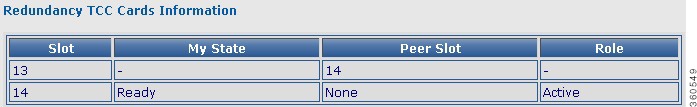
TCC Cards
Use this page to view TCC card redundancy information.
Figure 26 TCC Cards Page
Table 27 TCC Cards Page Field Description
Field
|
Description
|
Redundancy TCC Cards Information
|
Slot
|
Slot number where the TCC card resides in the chassis.
|
My State
|
Current state of the TCC card.
|
Peer Slot
|
Slot number of the peer TCC card.
|
Role
|
Active or standby.
|
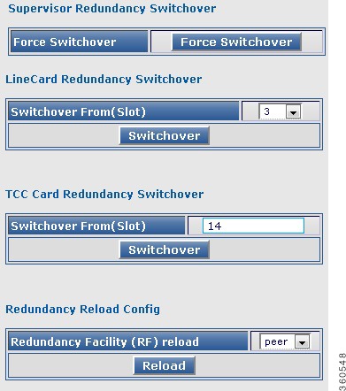
Switchover
Use this page to manage switchover of the different hardware components.
Figure 27 Switchover Page
Table 28 Switchover Page Field Description
Field
|
Description
|
Supervisor Redundancy Switchover
|
Force Switchover
|
Click Force Switchover to forcefully switch over the Supervisor cards in the chassis.
|
LineCard Redundancy Switchover
|
Switchover From(Slot)
|
Use the drop-down list to choose a line card (slot number) and click Switchover to make it switch over with its standby card.
|
TCC Card Redundancy Switchover
|
Switchover From(Slot)
|
Click Switchover to make it switch over with the standby TCC card.
|
Redundancy Reload Config
|
Redundancy Facility (RF) reload
|
Use the drop-down list to choose a reload type and click Reload to reset the cards.
Use peer to reload only the standby card or shelf to reload both the active and standby cards.
|
QAM
Use the tree-based navigation on the QAM page to do this:
•QAM—View QAM line card details.
•RF Profile—Create RF profiles.
•Frequency Profile—Create frequency profiles.
•Logical QAM Group—View logical QAM group details.
•Cable Mode—View assigned QAM cable mode details for the selected line card.
•DS384 slot—Configure RF port and QAM channel downstream parameters for a line card.
•QAM Replication—Create and manage QRGs.
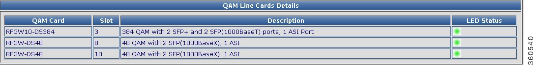
QAM
Use this page to view the QAM line card details.
Figure 28 QAM Page
Table 29 QAM Page Field Description
Field
|
Description
|
QAM Line Cards Details
|
QAM Card
|
Lists the QAM line cards installed in the chassis.
|
Slot
|
Slot number where the line card resides in the chassis.
|
Description
|
Describes the line card composition.
|
LED Status
|
Indicates the current state of the line card.
|
RF Profile
Use this page to view, edit, or delete existing RF profiles or create new RF profiles.
Figure 29 RF Profile Page
Table 30 RF Profile Creation Page Field Description
Field
|
Description
|
RF Profile Creation
|
Profile Id
|
Chassis level RF profile ID with name.
Note Enter only the RF profile name while creating a new RF profile. The ID is auto generated.
|
Modulation
|
Use the drop-down list to choose a QAM modulation format for the RF profile.
|
Annex
|
Use the drop-down list to choose an MPEG framing format (annex) for the RF profile.
|
Int Depth1
|
Use the drop-down list to choose the first interleaver depth value for the RF profile.
|
Int Depth2
|
Use the drop-down list to choose the second interleaver depth value for the RF profile.
|
Symbol Rate
|
Enter the symbol rate for the RF profile. The valid range is from 3500000 to 7000000 symbols per second.
|
Delete
|
Check the checkbox to delete an RF profile.
Or click Select All to check the Delete checkbox for all RF profile entries except the default RF profile, which was generated by the system.
|
Click Delete to delete the checked RF profile entries.
|
Click AddRow to add a new RF profile entry, Apply to accept changes or Reset to abort.
|
Frequency Profile
Use this page to view, edit, or delete existing frequency profiles or create new frequency profiles.
Figure 30 Frequency Profile Page
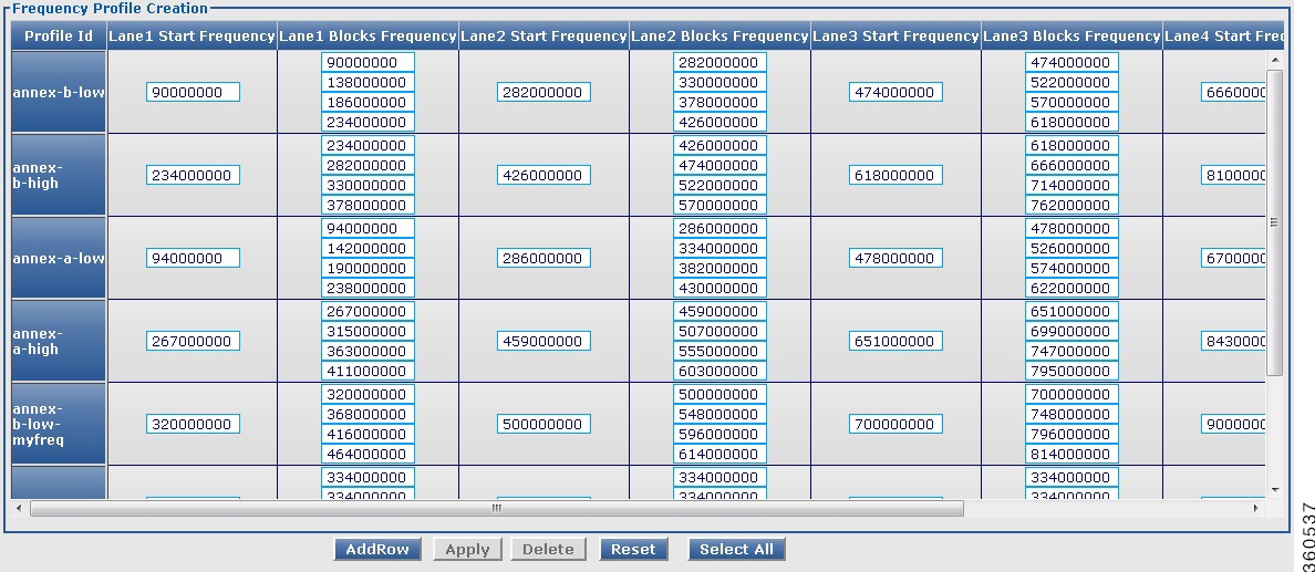
Table 31 Frequency Profile Creation Page Field Description
Field
|
Description
|
Frequency Profile Creation
|
Profile Id
|
Chassis level frequency profile name.
|
Lane1 Start Frequency
|
Enter lane 1 start frequency value. The valid range is from 48000000 to 995000000.
|
Lane1 Blocks Frequency
|
Enter lane 1 block start frequency. The valid range is from 48000000 to 995000000.
|
Lane2 Start Frequency
|
Enter lane 2 start frequency value. The valid range is from 48000000 to 995000000.
|
Lane2 Blocks Frequency
|
Enter lane 2 block start frequency. The valid range is from 48000000 to 995000000.
|
Lane3 Start Frequency
|
Enter lane 3 start frequency value. The valid range is from 48000000 to 995000000.
|
Lane3 Blocks Frequency
|
Enter lane 3 block start frequency. The valid range is from 48000000 to 995000000.
|
Lane4 Start Frequency
|
Enter lane 4 start frequency value. The valid range is from 48000000 to 995000000.
|
Lane4 Blocks Frequency
|
Enter lane 4 block start frequency. The valid range is from 48000000 to 995000000.
|
Delete
|
Check the checkbox to delete an RF profile.
Or click Select All to check the Delete checkbox for all frequency profile entries except the default frequency profile, which was generated by the system.
|
Click Delete to delete the checked frequency profile entries.
|
Click AddRow to add a new frequency profile entry, Apply to accept changes or Reset to abort.
|
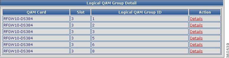
Logical QAM Group
Use this page to view logical QAM group details.
Figure 31 Logical QAM Group Page
Table 32 Logical QAM Group Page Field Description
Field
|
Description
|
Logical QAM Group Details
|
QAM Card
|
Lists the QAM line cards installed in the chassis.
|
Slot
|
Slot number where the line card resides in the chassis.
|
Logical QAM Group ID
|
Lists the logical QAM group identifier for the line card.
|
Action
|
Click Details to view detailed logical QAM group information for the Logical QAM Group ID.
|
Logical QAM Group-Slot: slot, Logical QAM Group ID: slot
|
RF Profile ID
|
The RF profile ID for the selected group ID.
|
First Port
|
First port location of the group ID.
|
Associated Qam Carrier ids
|
QAM carrier IDs associated with the first port of the group ID.
|
Second Port
|
Second port location of the group ID.
|
Associated Qam Carrier ids
|
QAM carrier IDs associated with the second port of the group ID.
|
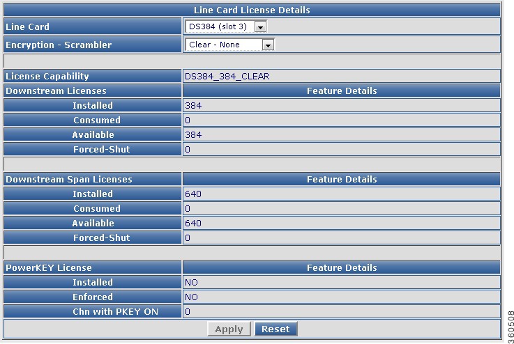
Cable Mode
Use this page to view the count of assigned and unassigned cable mode details for the selected line card.
Figure 32 Cable Mode Page
Table 33 Cable Mode Page Field Description
Field
|
Description
|
Line Card Cable Mode Information
|
Slot
|
Use the drop-down list to choose a line card to view its cable mode information.
|
Local DEPI Channels
|
Total number of local DEPI channels configured on the line card.
|
Remote DEPI Channels
|
Total number of remote DEPI channels configured on the line card.
|
Local Video Channels
|
Total number of local video channels configured on the line card.
|
Remote Video Channels
|
Total number of remote video channels configured on the line card.
|
Unassigned Channels
|
Total number of unassigned channels available on the line card.
|
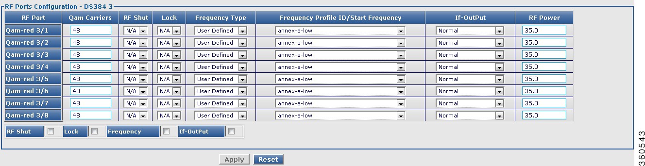
DS384 slot
Use this page to view or edit the existing RF port and QAM channel downstream parameters for the selected Cisco DS-384 line card.
Figure 33 RF Ports Configuration - DS384 slot Pane
Figure 34 QAM Channel Configuration - DS384 slot Pane
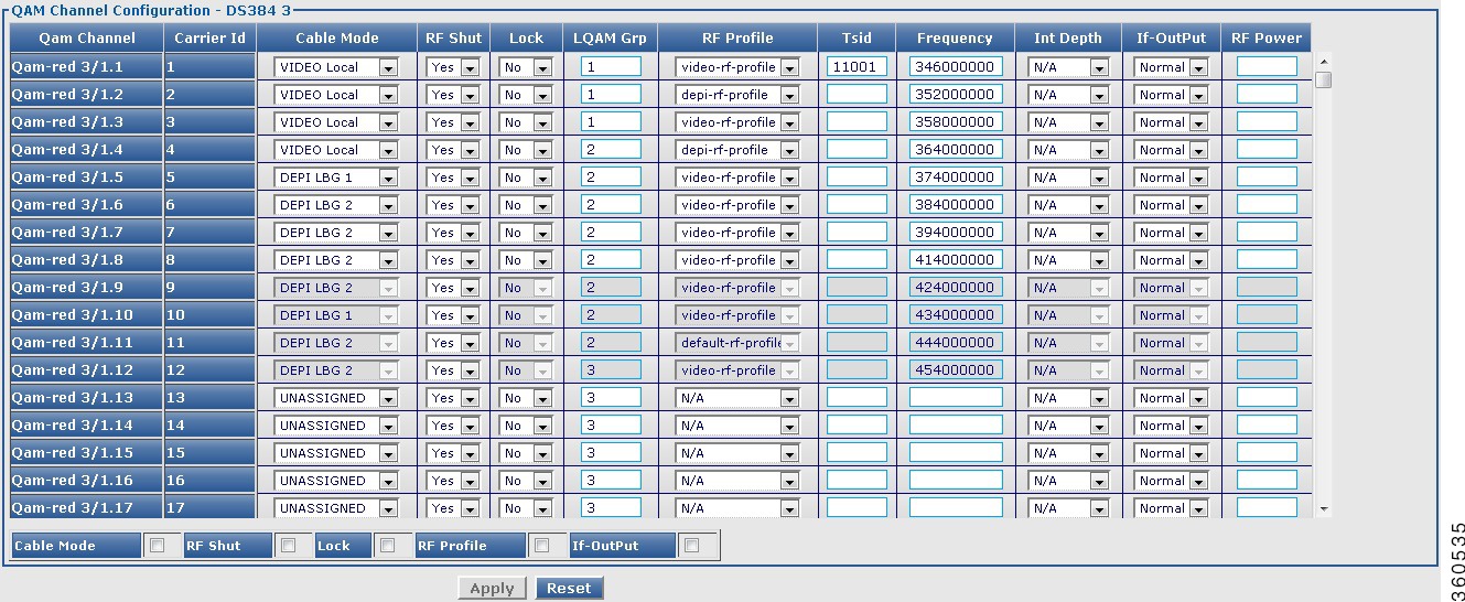
Table 34 DS384 slot Page Field Description
Field
|
Description
|
RF Ports Configuration - DS384 slot
|
RF Port
|
QAM interface information.
|
Qam Carriers
|
Enter the maximum number of QAM carrriers configurable on a port. The valid range is from 1 to 128. The acceptable values are 1/2 or multiples of 4.
|
RF Shut
|
Use the drop-down list to enable or disable the integrated upconverter on the line card.
Note This field is always displayed as N/A.
|
Lock
|
Use the drop-down list to lock or unlock the QAM interface configuration.
Note This field is always displayed as N/A.
|
Frequency Type
|
Use the drop-down list to set the frequency type for the RF port.
|
Frequency Profile ID/Start Frequency
|
When the Frequency Type is selected as User Defined, use the drop-down list to set the frequency profile to be used on the QAM interface.
When the Frequency Type is selected as Fixed, enter the start frequency for lane 1 on this port. The valid range for downstream frequency is from 45000000 to 995000000.
|
If-OutPut
|
Use the drop-down list to activate the downstream port.
Note This field is always displayed as Normal.
|
RF Power
|
Enter the default RF power value.
|
Click Apply to accept changes and Reset to abort.
Note Changes applied on an RF port are applied on the channels too.
|
QAM Channel Configuration - DS384 slot
|
Qam Channel
|
QAM interface information.
|
Carrier Id
|
Carrier ID of the QAM channel.
|
Cable Mode
|
Use the drop-down list to choose a cable mode for the QAM channel.
Note You can configure the DEPI and video cable modes.
|
RF Shut
|
Use the drop-down list to enable or disable the integrated upconverter on the line card.
|
Lock
|
Use the drop-down list to lock or unlock QAM interface configuration.
|
LQAM Grp
|
Enter the logical QAM group value. The valid range is from 1 to 48 per line card.
|
RF Profile
|
Use the drop-down list to choose the RF profile to be used on the QAM channel.
|
Tsid
|
Enter the downstream transport stream identifier. The valid range is from 1 to 65535.
|
Frequency
|
Enter the downstream carrier center frequency. The valid range is from 45000000 to 999000000.
|
Int Depth
|
Use the drop-down list to choose the interleaver depth value for the QAM channel.
|
If-OutPut
|
Use the drop-down list to activate the downstream port.
|
RF Power
|
Enter the RF output power level in dBmV. The valid range is from 30 to 60. The format is XY.Z and the default value for Z is 0.
|
Click Apply to accept changes and Reset to abort.
Note You can repeat these configurations at the RF port and QAM channel level using the tree-based navigation at the line card level.
|
DS48 slot
Use this page to view or edit the existing RF port and QAM channel downstream parameters for the selected Cisco DS-48 line card.
Figure 35 RF Ports Configuration - DS48 slot Pane
Figure 36 QAM Channel Configuration - DS48 slot Pane
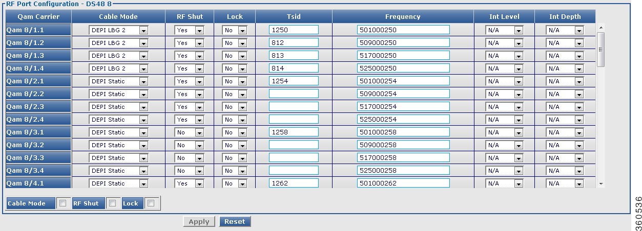
Table 35 DS48 slot Page Field Description
Field
|
Description
|
RF Ports Configuration - DS48 slot
|
RF Port
|
QAM interface information.
|
RF Shut
|
Use the drop-down list to enable or disable the integrated upconverter on the line card.
|
Stacking
|
Use the drop-down list to set the frequency stacking.
|
Annex Type
|
Use the drop-down list to set the MPEG framing format.
|
Frequency
|
Enter the first QAM downstream center frequency. The valid range for downstream frequency is from 85000000 to 999000000.
|
If-OutPut
|
Use the drop-down list to activate the downstream port.
|
Modulation
|
Use the drop-down list to set the QAM modulation format.
|
RF Power
|
Enter the RF output power level in dBmV. The valid range is from 30 to 60. The format is XY.Z and the default value for Z is 0.
|
Symbol Rate
|
Enter the symbol rate. The valid range is from 3500000 to 7000000.
|
Click Apply to accept changes and Reset to abort.
Note Changes applied on an RF port are applied on the channels too.
|
QAM Channel Configuration - DS48 slot
|
Qam Carrier
|
QAM interface information.
|
Cable Mode
|
Use the drop-down list to choose a DEPI mode for the QAM channel.
Note Video features are not supported on the Cisco DS-48 line card.
|
RF Shut
|
Use the drop-down list to enable or disable the integrated upconverter on the line card.
|
Lock
|
Use the drop-down list to lock or unlock QAM interface configuration.
|
Tsid
|
Enter the downstream transport stream identifier. The valid range is from 1 to 65535.
|
Frequency
|
Enter the downstream carrier center frequency. The valid range is from 85000000 to 999000000.
|
Int Level
|
Use the drop-down list to choose the interleaver level value for the QAM channel.
|
Int Depth
|
Use the drop-down list to choose the interleaver depth value for the QAM channel.
|
Click Apply to accept changes and Reset to abort.
Note You can repeat these configurations at the RF port and QAM channel level using the tree-based navigation at the line card level.
|
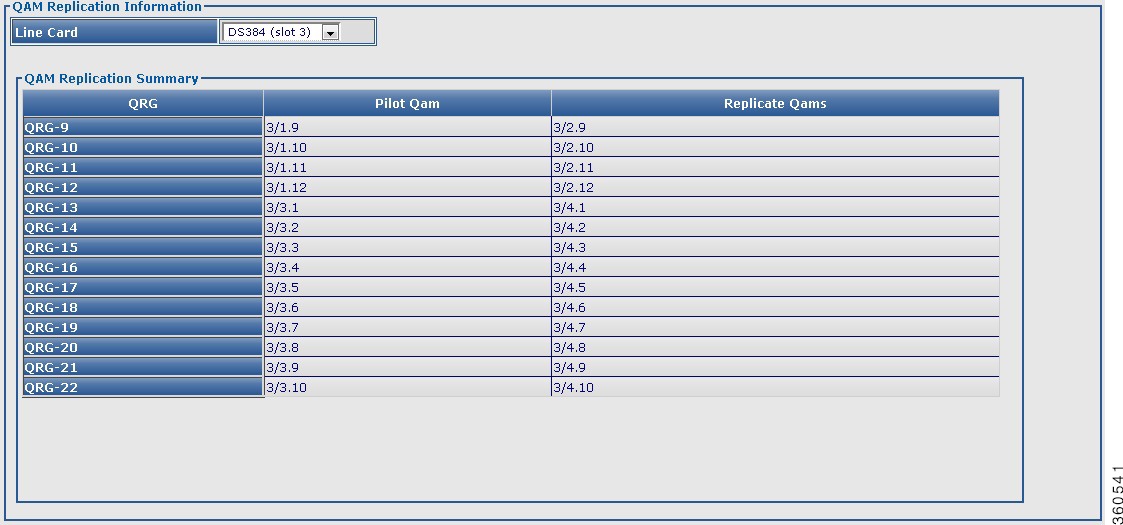
QAM Replication
Use this page to view configured QRG information for selected line card or all line cards in the chassis.
Figure 37 QAM Replication Page
Table 36 QAM Replication Page Field Description
Field
|
Description
|
QAM Replication Information
|
Line Card
|
Use the drop-down list to choose a line card or all to view its QAM replication summary information.
|
QAM Replication Summary
|
QRG
|
QAM replication group (QRG) configured on the line card.
|
Pilot QAM
|
Pilot QAM of the QRG.
|
Replicate QAMs
|
Replicate QAMs of the pilot QAM in a QRG.
|
DS384 slot
Use this page to view, or edit existing QAM replication information or add new QAM replication groups.
Figure 38 Qam Replication- DS384 slot Page
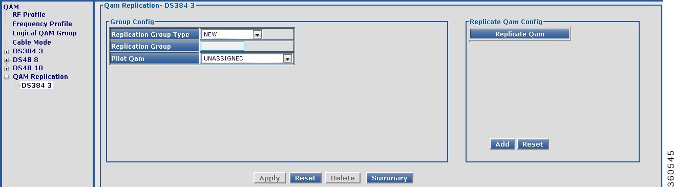
Table 37 DS384 slot Page Field Description
Field
|
Description
|
Qam Replication- DS384 slot
|
Qam Replication Group Summary
|
QRG
|
QAM replication group (QRG) configured on the line card.
|
Pilot QAM
|
Pilot QAM of the QRG.
|
Replicate QAMs
|
Replicate QAMs of the pilot QAM in a QRG.
|
Click Add QRG to view Group Config pane to add, edit or delete a QRG.
|
Group Config
|
Replication Group Type
|
Use the drop-down list to choose a replication group type.
•NEW—To create a new group and assign a group number automatically.
•Exist—To list existing QRGs in the Replication Group drop-down list and edit or delete its information.
•USER DEFINED—To create a new group and manually assign a group number to it.
|
Replication Group
|
Enter the QAM group name.
|
Pilot Qam
|
Use the drop-down list to assign a QAM interface as the pilot QAM for the QRG.
|
Replicate Qam Config
|
Replicate Qam
|
Click Add and use the drop-down list to assign replicate QAMs for the pilot QAM in the QRG.
|
Click Apply to accept changes, Reset to abort, Delete to delete a QRG entry or Summary to view the QAM Replication Group Summary pane.
|
DEPI
Use the tree-based navigation on the DEPI page to do the following:
•DEPI—View DEPI session count information for the chassis and line card.
•DEPI Class—Create new DEPI class and view existing DEPI class information.
•L2TP Class—Create new L2TP class and view existing L2TP class information.
•DEPI Tunnel—Create DEPI tunnels and view existing DEPI tunnel information.
•Session—View chassis and line card DEPI manual and L2TP session information.
DEPI
Use this page to view chassis and line card DEPI session count information.
Figure 39 DEPI Page
Table 38 DEPI Page Field Description
Field
|
Description
|
DEPI Global Session Information
|
Total Manual DEPI Session
|
Total number of manual DEPI sessions on the chassis.
|
Total L2TP DEPI Session
|
Total number of L2TP DEPI sessions on the chassis.
|
Total DEPI Session
|
Total number of DEPI sessions on the chassis.
|
DEPI Line Card Session Information
|
Slot
|
Slot where the line card resides.
|
Total Manual DEPI Session
|
Total number of manual DEPI sessions on the line card.
|
Total L2TP DEPI Session
|
Total number of L2TP DEPI sessions on the line card.
|
Total DEPI Session
|
Total number of DEPI sessions on the line card.
|
DEPI Class
Use this page to create and configure DEPI classes.
Figure 40 DEPI Class Page
Table 39 DEPI Class Page Field Description
Field
|
Description
|
DEPI Class Configuration
|
DEPI Class Name
|
Enter the DEPI class name.
|
DEPI Mode
|
Use the drop-down list to configure the DEPI mode.
|
Click Apply to accept changes or Summary to view all the DEPI classes configured in the chassis.
|
DEPI Class Information
|
DEPI Class Name
|
Lists all the DEPI classes configured in the chassis.
|
Delete
|
Check the checkbox to delete a DEPI class.
Or click Select All to check the Delete checkbox for all DEPI class entries.
|
Click Delete to delete the checked DEPI class entries.
|
L2TP Class
Use this page to view or configure DEPI L2TP class information.
Figure 41 L2TP Page
Figure 42 L2TP Advanced Configuration Page
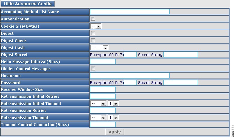
Table 40 DEPI Class Page Field Description
Field
|
Description
|
L2TP Class Configuration
|
L2TP Class Name
|
Enter the L2TP class name.
|
Click Apply to accept changes or Summary to view all the L2TP classes configured in the chassis.
|
L2TP Class Information
|
L2TP Class Name
|
Lists all the L2TP classes configured in the chassis.
|
Delete
|
Check the checkbox to delete a L2TP class.
Or click Select All to check the Delete checkbox for all L2TP class entries.
|
Click Delete to delete the checked L2TP class entries.
|
Click Show Advanced Config to configure advanced L2TP class configuration.
|
Accounting Method List Name
|
Method list used for accounting.
|
Authentication
|
Check to authenticate the L2TP control connection.
|
Cookie Size(Bytes)
|
Local cookie option. Use the drop-down list to set the cookie size.
|
Digest
|
Check the checkbox to send digest authentication messages for the L2TP control connection.
|
Digest Check
|
Check the checkbox to enable message digest validation.
|
Digest Hash
|
Use the drop-down list to choose the message digest hash function.
|
Digest Secret
|
Enter the message digest shared secret encryption and string.
|
Hello Message Interval(Secs)
|
Enter the HELLO message interval.
|
Hidden Control Messages
|
Check the checkbox to hide AVPs in outgoing control messages.
|
Hostname
|
Enter the local hostname for control connection authentication.
|
Password
|
Enter the password for control connection authentication, AVP hiding.
|
Receive Window Size
|
Enter the receive window size for the control connection.
|
Retransmission Initial Retries
|
Enter the control message retransmission parameters.
|
Retransmission Initial Timeout
|
Use the drop-down list to set the minimum or maximum number of retries before tearing down a control connection.
|
Retransmission Retries
|
Enter the SCCRQ message retry or timeout settings.
|
Retransmission Timeout
|
Use the drop-down list to set the minimum or maximum number of retries before tearing down a control connection.
|
Timeout Control Connection(Secs)
|
Enter the control connection timeout parameters.
|
Click Apply to accept changes. Click Hide Advanced Config to hide the advanced configuration fields.
|
DEPI Tunnel
Use this page to view or configure the DEPI tunnel.
Figure 43 DEPI Tunnel Page
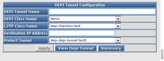
Table 41 DEPI Tunnel Page Field Description
Field
|
Description
|
DEPI Tunnel Configuration
|
DEPI Tunnel Name
|
Enter the DEPI tunnel name.
|
DEPI Class Name
|
Use the drop-down list to choose a DEPI class for the DEPI tunnel.
|
L2TP Class Name
|
Use the drop-down list to choose an L2TP class for the DEPI tunnel.
|
Destination IP Address
|
Enter the CMTS IP address.
|
Protect Tunnel
|
Use the drop-down list to choose the protect tunnel for the DEPI tunnel.
|
Click Apply to accept changes. Click Summary to view all the DEPI tunnels configured in the chassis. Click View DEPI Tunnel to view the DEPI tunnel information.
|
DEPI Tunnel Information
|
DEPI Tunnel Name
|
Lists all the DEPI tunnels configured in the chassis.
|
Delete
|
Check the checkbox to delete a DEPI tunnel.
Or click Select All to check the Delete checkbox for all DEPI tunnel entries.
|
Click Delete to delete the checked DEPI tunnel entries.
|
DEPI Tunnel Information
|
Local Tunnel ID
|
Local tunnel IDs.
|
Remote Tunnel ID
|
Remote tunnel IDs.
|
Remote Name
|
Remote tunnel name.
|
State
|
State of the tunnel.
|
Remote Address
|
Remote tunnel IP address.
|
Session Count
|
Session count for the DEPI tunnel.
|
L2TP Class
|
L2TP class information for the DEPI tunnel.
|
Session
Use this page to view chassis and line card DEPI session count information.
Figure 44 Session Page
Table 42 Session Page Field Description
Field
|
Description
|
DEPI Global Session Information
|
Total Manual DEPI Session
|
Total number of manual DEPI sessions on the chassis.
|
Total L2TP DEPI Session
|
Total number of L2TP DEPI sessions on the chassis.
|
Total DEPI Session
|
Total number of DEPI sessions on the chassis.
|
DEPI Line Card Session Information
|
Slot
|
Slot where the line card resides. Use the drop-down list to choose a line card and click View Details to view its DEPI session information.
|
Total Manual DEPI Session
|
Total number of manual DEPI sessions on the line card.
|
Total L2TP DEPI Session
|
Total number of L2TP DEPI sessions on the line card.
|
Total DEPI Session
|
Total number of DEPI sessions on the line card.
|
DEPI Session Slot slot Details
|
Session ID
|
DEPI session ID. Click a session ID to view its DEPI session information.
|
Session Type
|
DEPI session type.
|
Session State
|
DEPI session current state.
|
QAM Chn
|
QAM channel information for the DEPI session.
|
PW Type
|
DEPI mode for the DEPI session.
|
Carrier ID
|
Carrier ID for the DEPI session.
|
Line Card slot
Use this page to view or configure DEPI sessions on a line card.
Figure 45 Line Card slot Cable Mode Configuration Page
Figure 46 Line Card slot DEPI Session Configuration Pane
Figure 47 DEPI Session Slot slot Information Pane
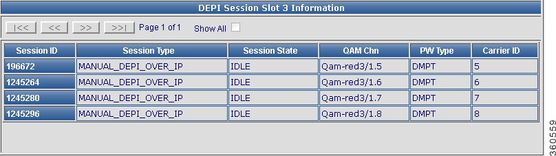
Table 43 Session Page Field Description
Field
|
Description
|
Line Card slot Cable Mode Configuration
|
Qam Channel
|
QAM channel information.
|
Cable Mode
|
Configured cable mode information (DEPI/Video/Unassigned).
|
Session Type
|
Use the drop-down list to choose a DEPI session parameter for manual or L2TP DEPI sessions.
|
Offset
|
Enter the DOCSIS timing offset for the QAM channel.
|
Click Apply to accept changes or Reset to abort.
|
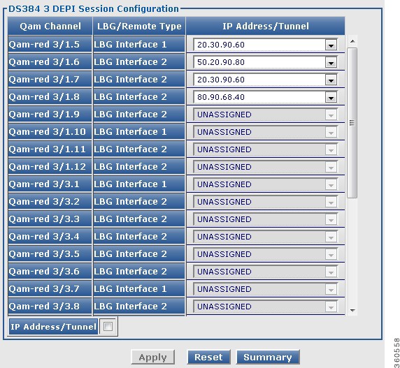
Line Card slot DEPI Session Configuration
|
Qam Channel
|
QAM channels with mode set as DEPI.
|
LBG/Remote Type
|
DEPI cable mode details for the QAM channel.
|
IP Address/Tunnel
|
Use the drop-down lis to choose the destination IP address or the DEPI tunnel name for the QAM channel.
|
Click Apply to accept changes or Reset to abort.
Click Summary to view summary information of all DEPI sessions configured on the line card.
|
DEPI Session Slot slot Information
|
Session ID
|
DEPI session ID. Click a session ID to view its DEPI session information.
|
Session Type
|
DEPI session type.
|
Session State
|
DEPI session current state.
|
QAM Chn
|
QAM channel information for the DEPI session.
|
PW Type
|
DEPI mode for the DEPI session.
|
Carrier ID
|
Carrier ID for the DEPI session.
|
Note The same depi session configurations can be done at the RF port and QAM channel level using the tree-based navigation available at the line card level.
|
Video
Use the tree-based navigation on the Video page to do the following:
•Video—View video session count information for chassis and line card.
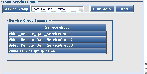
•QAM-Service Group—Create new QAM service groups and update information for existing QAM service groups.
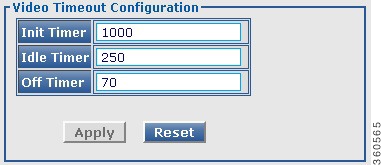
•Video Timeout—Configure video timeout parameters.
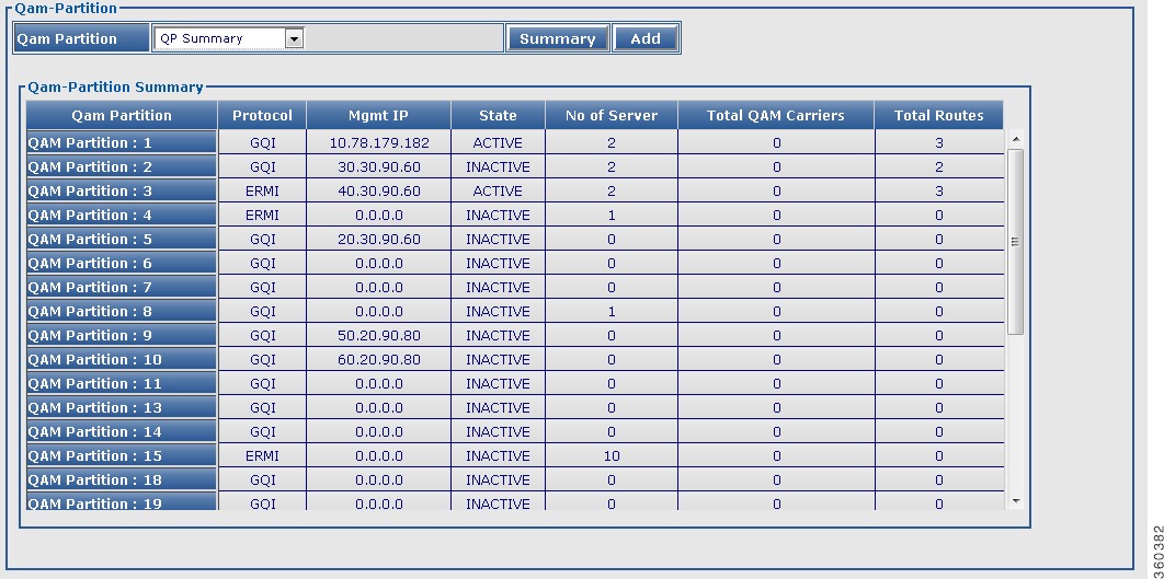
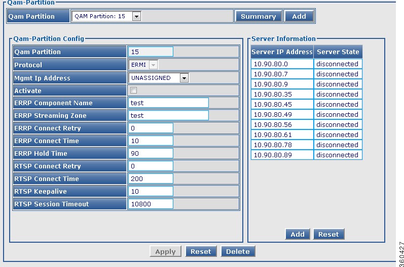
•QAM Partition—Create new QAM partitions and update information for existing QAM partitions.
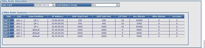
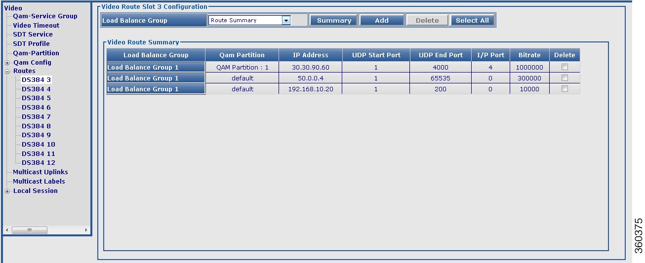
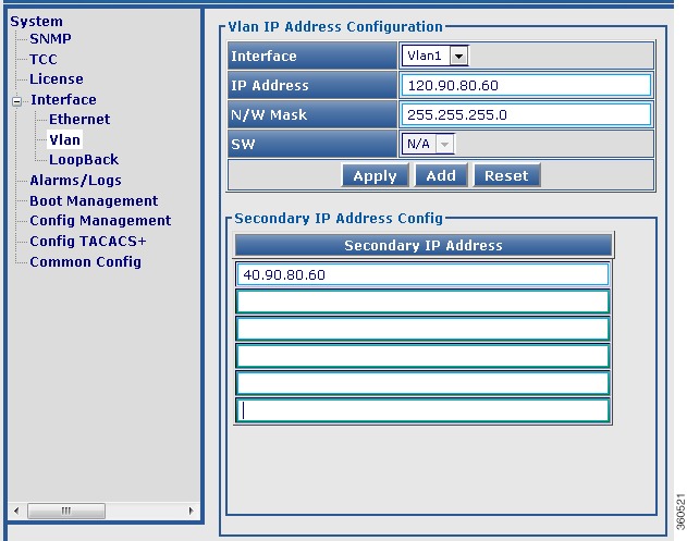
•Routes—View summary information of existing routes, create new routes and update information for existing routes.
•Multicast Uplinks—Configure multicast routing, multicast uplinks and PIM information.
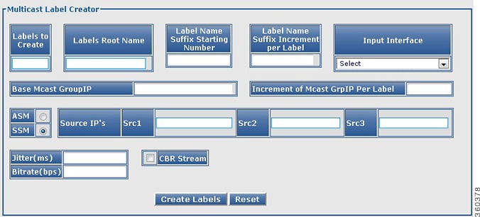
•Multicast Labels—View summary information of existing multicast labels, create new multicast labels and update information for existing multicast labels.
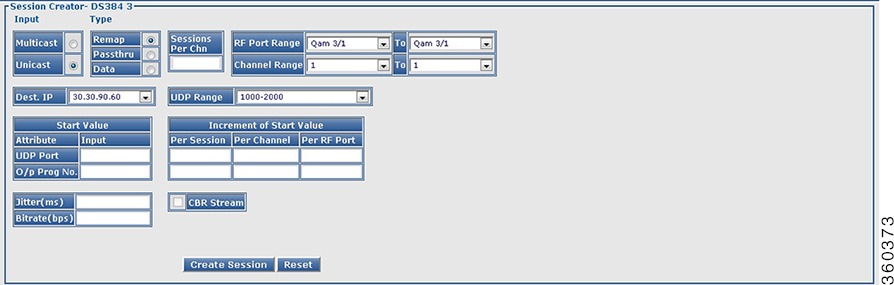
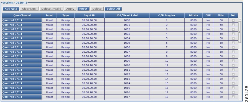
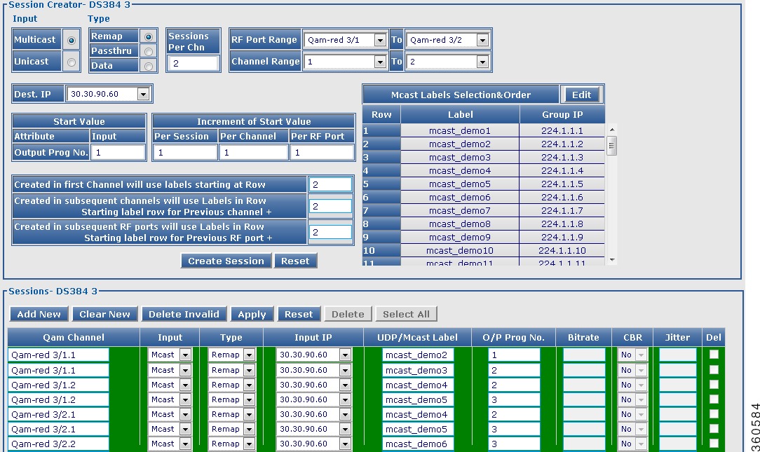
•Local Session—View summary information of existing local sessions, create new local sessions and update information for existing local sessions.
Video
Use this page to view the chassis and line card video session count information.
Figure 48 Video Page
Table 44 Video Page Field Description
Field
|
Description
|
Video Global Session Information
|
Total Unicast Session
|
Total number of unicast sessions on the chassis.
|
Total Multicast Session
|
Total number of multicast sessions on the chassis.
|
Total Video Session
|
Total number of video sessions on the chassis.
|
Video Line Card Session Information
|
Slot
|
Slot where the line card resides.
|
Total Unicast Session
|
Total number of unicast sessions on the line card.
|
Total Multicast Session
|
Total number of multicast sessions on the line card.
|
Total Video Session
|
Total number of video sessions on the line card.
|
QAM-Service Group
Use this page to create new QAM service group and for updating information for existing QAM groups that belong to a particular service group.
Figure 49 QAM-Service Group Pane
Figure 50 QAM-Service Group Config Pane
Table 45 QAM-Service Group Page Field Description
Field
|
Description
|
Qam-Service Group
|
Service Group
|
Lists the QAM service groups configured on the chassis and QAM service group summary. Use the drop-down list to:
•Choose Qam-Service Summary to view the Service Group Summary pane.
Note Or click the Summary button to view the Service Group Summary pane.
or
•Choose a QAM service group to view, edit, add or delete its QAM group.
|
Service Group Summary
|
Service Group
|
Lists all QAM service groups. Click a group name to view, edit, add or delete QAM groups to it.
Note You can configure a maximum of 50 QAM service groups and QAM groups.
|
Click Add button in the Qam-Service Group pane to create a new QAM service group and add QAM groups to it in the Qam-Service Group Config pane.
|
Qam-Service Group Config
|
Service Group
|
Enter the QAM service group name.
|
Qam Group
|
Enter the QAM group information and click Add button to add it to the QAM service group.
|
Click Apply button to accept changes, Reset button to abort, or Delete button to delete an entry.
|
Video Timeout
Use this page to configure video timeout parameters.
Figure 51 Video Timeout Configuration Page
Table 46 Video Timeout Page Field Description
Field
|
Description
|
Init Timer
|
Timeout threshold value for init sessions. The valid range is from 100 to 60000 (in msec).
|
Idle Timer
|
Timeout threshold value for idle sessions. The valid range is from 100 to 5000 (in msec).
|
Off Timer
|
Timeout threshold value for off sessions. The valid range is from 1 to 4294967295 (in seconds).
|
Click Apply button to accept changes or click Reset button to abort.
|
QAM Partition
Use this page to create new user-defined QAM partitions and for updating information for existing QAM partitions that belong to a particular partition.
Figure 52 QAM-Partition Summary Pane
Figure 53 QAM-Partition Config for ERMI protocol Pane
Figure 54 QAM-Partition Config for GQI protocol Pane
Table 47 QAM Partition Page Field Description
Field
|
Description
|
Qam Partition
|
Qam Partition
|
Lists the QAM partitions configured on the chassis and QP summary. Use the drop-down list to:
•Choose QP Summary to view the Qam-Partition Summary pane.
Note Or click the Summary button to view the Qam-Partition Summary pane.
or
•Choose a QAM partition to view, edit or delete information.
|
Qam Partition Summary
|
Qam Partition
|
Lists all QAM partitions configured in the system. Click a QAM partition to view and edit its information in the Qam-Partition Config pane.
|
Protocol
|
Protocol used for communicating with the video server (GQI or ERMI).
|
Mgmt IP
|
Management IP address for the QAM partition.
|
State
|
Current state of the QAM partition.
|
No of Server
|
Number of servers.
|
Total QAM Carriers
|
Total number of QAM carriers in the QAM partition.
|
Total Routes
|
Total number of routes used by the QAM partition.
|
Qam-Partition Config
In the Add mode, you can edit all the fields, but in the edit mode, you can edit only some fields.
|
Qam Partition
|
View or add a QAM partition.
You can create 50 user-defined QAM partitions. These are used for remote video sessions.
|
Protocol
|
View or use the drop-down list to choose the protocol to be used for communicating with the video server (GQI or ERMI).
|
Mgmt Ip Address
|
View or use the drop-down list to choose the management IP address for the QAM partition.
|
Activate
|
Check or uncheck the checkbox to activate or deactivate the QAM partition.
Note You cannot edit a QAM partition in active state.
|
The following fields are listed when the protocol used for communicating with the video server is set as GQI.
|
MAC Address
|
View or use the drop-down list to choose the Cisco RFGW-10 MAC address.
|
Timeout Period
|
Enter the time interval (in seconds) between the keepalive retry attempts. The valid range is from 1 to 45.
|
Number of Retry
|
Enter the keepalive retry time interval. A maximum of three retry attempts are allowed. The valid retry range is from 0 to 10. The default keepalive is 5 seconds.
|
SDV Bindings service
|
Specify the SDV binding service.
|
The following fields are listed when the protocol used for communicating with the video server is set as ERMI.
|
RTSP connect-retry
|
Enter the RTSP connection retry time interval. The valid range is from 1 to 10.
|
RTSP connect-time
|
Enter the RTSP connection time in seconds. The valid range is from 10 to 200.
|
RTSP keepalive
|
Enter the keepalive time interval for the RTSP connection. The valid range is from 1 to 300.
|
RTSP session-timeout
|
Enter the RTSP session timeout interval for the connection. The valid range is from 10800 to 36000.
|
ERRP component-name
|
Enter the ERMI component name for the QAM partition.
|
ERRP connect-retry
|
Enter the connection retry time interval in seconds. The valid range is from 1 to 10.
|
ERRP connect-time
|
Enter the connection time in seconds. The valid range is from 10 to 100.
|
ERRP hold-time
|
Enter the hold time in seconds. The valid range is from 3 to 240 seocnds.
|
ERRP streaming-zone
|
Enter the ERMI streaming zone for the QAM partition.
|
Server Information
|
Server IP Address
|
View or add the IP address of an external server. You can add a maximum of three servers when the protocol is GQI or a maximum of 10 servers when the protocol is ERMI.
|
Server State
|
Displays the current state of the server.
|
Click Apply button to accept changes, Reset button to abort, Delete button to delete an entry, or Add button to add information.
|
QAM Config
Use this page to manage and assign video QAM related configuration for a line card.
DS384 Line Card
Use this page to manage and assign QAM partitions to a QAM channel.
Figure 55 DS384 slot Video Qam Channel Configuration Pane
Table 48 DS384 Line Card Video QAM Channel Configuration Page Field Description
Field
|
Description
|
Qam Channel
|
Lists the QAM channels available on the line card.
|
Cable Mode
|
QAM channel cable video mode. Use the drop-down list to select a cable video mode for the QAM channel.
Cable video modes include:
•Video Clear—Configures video session remotely.
•Video Encrypt—Enables encryption for remote video session on the QAM.
•Video Local—Configures video session locally.
|
Qam-Partition
|
Lists the QAM partition IDs configured on the line card. The valid range is from 1 to 50.
Use the drop-down list to assign a QAM partition to the QAM channel.
You must configure the QAM channel to include it in video clear or video encrypt cable mode, and you must create the partition before assigning it to the channel.
|
Ext-Channel
|
Enter the output port number used in ERM to represent a QAM channel and for GQI protocol QAM partition. The valid range is from 1-65535.
|
Qam Group
|
Lists the QAM groups configured on the line card.
Use the drop-down list to assign a QAM group to the QAM channel.
You must configure the QAM channel to include it in video clear or video encrypt cable mode, and you must create the partition before assigning it to the channel.
|
PSI-Interval
|
Enter the Program Specific Information (PSI) nterval. The valid range is from 40 to 1000 ms. The default value is 100 ms.
|
Click Apply button to accept changes or Reset button to abort.
|
Note You can repeat these configurations at the RF port and QAM channel level using the tree-based navigation at the line card level.
|
Routes
Use this page to view configured route details for specific line card and load balancing groups.
Figure 56 Video Route Summary Pane
Table 49 Video Route Information Page Field Description
Field
|
Description
|
Video Route Information
|
Line Card
|
Use the drop-down list to select a line card to view its video route information or All to view a summary of all routes configured on the line card.
|
Load Balance Group
|
Use the drop-down list to select a load balance group available on the selected line card to view its route information or All to view a summary of all load balancing group route information.
|
Table 50 Video Route Summary Page Field Description
Field
|
Description
|
Video Route Summary
|
Slot
|
Slot number of the line card.
|
LBG
|
Load balancing group identifier.
|
Qam Partition
|
QAM partition number.
|
IP Address
|
Destination IP address.
|
UDP Start Port
|
Starting UDP port number.
|
UDP End Port
|
Ending UDP port number.
|
I/P Port
|
GQI ingress port number.
|
Res Bitrate
|
Reserved bitrate (in Kbps).
|
Alloc Bitrate
|
Allocated bitrate (in Kbps).
|
Sessions
|
Number of sessions.
|
DS384 Line Card
Use this page to view or configure a Cisco DS-384 line card video route information.
Figure 57 Video Route Slot slot Summary Pane
Figure 58 Video Route Config Pane
Table 51 Video Route Slot slot Configuration Page Field Description
Field
|
Description
|
Video Route Slot slot Configuration
|
Load Balance Group
|
Lists the load balance groups on the line card and Route Summary. Use the drop-down list to:
•Choose Route Summary to view complete route summary information.
Note Or click the Summary button to view complete route summary information.
or
•Choose a load balance group to view its information.
|
Video Route Summary
|
Load Balance Group
|
Load balancing groups. Click a group to edit its information in the Video Route Config pane.
|
Qam Partition
|
QAM partition number.
|
IP Address
|
Destination IP address.
|
UDP Start Port
|
Starting UDP port number.
|
UDP End Port
|
Ending UDP port number.
|
I/P Port
|
GQI ingress port number.
|
Bitrate
|
Reserved bitrate (in Kbps).
|
Delete
|
Check the checkbox against an entry and click Delete button to delete its information.
|
Video Route Config
In the Add mode, you can edit all fields, but in the Edit mode, you can edit only some fields.
|
Note In Edit mode, the route being edited is first deleted and then created as new with the latest information.
|
Load Balance Group
|
Choose a load balancing group identifier. The valid value is 1 or 2.
|
Qam Partition
|
Choose a QAM partition identifier. The valid range is from 1 to 50. Default partition IDs are used for local video sessions.
|
Ip Address
|
Destination IP address of the video route.
|
UDP Start Port
|
Enter the starting or low UDP port number. The valid range is from 1 to 65535.
|
UDP End Port
|
Enter the ending or high UDP port number. The valid range is from 1 to 65535.
|
Input Port
|
Enter the input port number for the GQI interface. The valid range is from 1 to 100.
|
Bitrate
|
Enter the reserved bandwidth to be used for the partition in Kbps. The valid range is 1 to 9100000.
|
Click Apply button to accept changes or Reset button to abort.
|
Multicast Uplinks
Use this page to do the following:
•Multicast Routing and PIM—Enable or disable multicast routing and PIM SSM.
Note You must enable multicast routing on the Cisco RFGW-10 before setting the GigabitEthernet or TenGigabitEthernet port for multicast routing. The interfaces that receive the multicast traffic must also be set in multicast mode.
•Multicast Uplink—Configure multicast routing such as uplink interface, backup interface and bandwidth.
Figure 59 Multicast Uplinks Pane
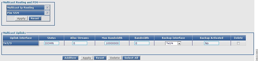
Table 52 Multicast Uplinks Page Field Description
Field
|
Description
|
Multicast Routing and PIM
|
Multicast IP Routing
|
Select or deselect multicast IP routing.
|
Pim SSM
|
Select or deselect PIM SSM.
|
Multicast Uplinks
|
Uplink Interface
|
GigabitEthernet or TenGigabitEthernet uplink interface number.
|
Status
|
Status of the uplink interface.
|
Alloc Streams
|
Allocated number of streams for the uplink interface.
|
Max Bandwidth
|
Maximum bandwidth for the uplink interface (in Kbps). The valid range is from 1 to 1000000.
|
Bandwidth
|
Bandwidth of the uplink interface (in Kbps). The valid range is from 1 to 1000000.
|
Backup Interface
|
Use the drop-down list to choose the backup interface for the uplink interface.
|
Backup Activated
|
Backup activation status for the uplink interface.
|
Delete
|
Check the checkbox against an entry and click Delete button to delete its information.
|
Click AddRow button to add an entry, Select All button to select all entries listed in this page, Apply button to accept changes or Reset button to abort.
|
Multicast Labels
Use this page to create new multicast labels for video sessions. You can create both ASM and SSM multicast labels. This page has two panes for label creation; Multicast Label Creator and Labels.
Use Multicast Label Creator pane to create multiple label entries with the same information at a time.
Use the Add New button in the Labels pane to create one label at a time.
Figure 60 Multicast Label Creator Pane
Figure 61 Labels Pane
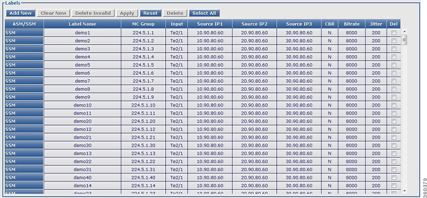
Table 53 Multicast Labels Page Field Description
Field
|
Description
|
Multicast Label Creator
|
Labels to Create
|
Enter the number of labels to be created.
Note A maximum of 500 labels is recommended in an attempt for higher performance.
|
Labels Root Name
|
Enter the multicast label name. For example, video_multicast.
|
Label Name Suffix Starting Number
|
Enter a numerical value to be suffixed to the multicast label name. For example, video_multicast1.
|
Label Name Suffix Increment per Label
|
Enter a numerical value to be used for incrementing the label name suffix starting number (per label).
|
Input Interface
|
Use the drop-down list to choose the input interface.
|
Base Mcast GroupIP
|
Enter the IP address for the multicast group.
|
Increment of Mcast GrpIP Per Label
|
Enter the increment value for the multicast group IP address per label.
|
ASM
|
Select to configure the Any Source Multicast (ASM) session definition.
|
SSM
|
Select to configure the Source Specific Multicast (SSM) session definition.
|
Source IP's
|
Enter the multicast source IP address pairs (Src1, Src2, Src3). An SSM session is identified by the source or group IP address pairs. Specify a maximum of three multicast address pairs in an SSM multicast session.
|
Jitter(ms)
|
Enter the jitter buffer size in ms. The valid range is from 10 to 200.
|
Bitrate(bps)
|
Enter the bitrate of the session in bps. The valid range is from 1 to 52000000.
|
CBR Stream
|
Select or deselect constant bitrate streaming.
|
Click Create Labels button to create labels or Reset button to abort.
|
Labels
|
Click Add New button to add a new label, Clear New button to clear the newly added label, Delete Invalid button to delete all invalid labels, Apply button to accept changes, Reset button to abort, Delete button to delete the selected label entry, and Select All button to select all label entries listed in this page.
Click a label to edit its information. In edit mode, the label being edited is first deleted and then created as new with the latest information.
|
ASM/SSM
|
Use the drop-down list to choose either ASM or SSM.
|
Label Name
|
Enter the label name.
|
MC Group
|
Enter the multicast group IP address.
|
Input
|
Use the drop-down list to choose the input interface for the label.
|
Source IP1, Source IP2, Source IP3
|
Enter the source IP address for the label.
|
CBR
|
Use the drop-down list to set or unset constant bitrate session.
|
Bitrate
|
Enter the bitrate value for the label.
|
Jitter
|
Enter the jitter value for the label.
|
Delete
|
Check the checkbox against an entry and click Delete button to delete its information.
|
Note Invalid entries are highlighted in red color.
Note On clicking Apply, if there are invalid entries, an alert message is displayed for deleting all invalid entries.
|
Local Session
Use this page to view chassis and line card video local session count information.
Figure 62 Video Session slot slot Details Pane
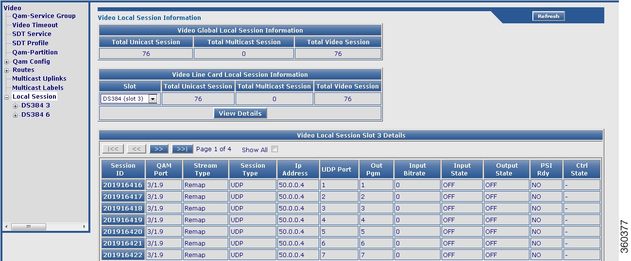
Table 54 Local Session Page Field Description
Field
|
Description
|
Video Global Session Information
|
Total Unicast Session
|
Total number of unicast video sessions on the chassis.
|
Total Multicast Session
|
Total number of multicast video sessions on the chassis.
|
Total Video Session
|
Total number of video sessions on the chassis.
|
Video Line Card Session Information
|
Slot
|
Use the drop-down list to choose a slot and click View Details button to view its video session details.
|
Total Unicast Session
|
Total number of unicast video sessions on the selected line card.
|
Total Multicast Session
|
Total number of multicast video sessions on the selected line card.
|
Total Video Session
|
Total number of video sessions on the selected line card.
|
Video Session Slot All Details
|
Session ID
|
Click a session ID to view its detailed video session information.
|
QAM Port
|
QAM port information.
|
Stream Type
|
Video session stream type.
|
Session Type
|
Video session type.
|
Ip Address
|
Video session IP address.
|
UDP Port
|
UDP port number.
|
Out Pgm
|
Single ProgramTransport Stream (SPTS) or Multiple ProgramTransport Stream (MPTS) program number.
|
Input Bitrate
|
Actual bitrate measured on the input.
|
Input State
|
State on the input.
|
Output State
|
State on the output.
|
PSI Rdy
|
PSI ready state.
|
Ctrl State
|
Controller state.
|
DS384 Line Card
Use this page to create or edit unicast or multicast local video sessions on a specific Cisco DS-384 line card.
Figure 63 Session Creator Pane
Figure 64 Sessions Pane
Figure 65 Mcast Labels Selection&Order Pane
Figure 66 Multicast Label Selection Window
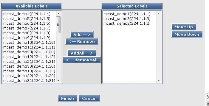
Table 55 DS384 Line Card Local Session Page Field Description
Field
|
Description
|
Session Creator - DS384 slot
|
Input
|
Choose either Multicast or Unicast for session inputs.
If the input is Multicast, click Edit button available next to Mcast Labels Selection&Order to view, order or select existing multicast labels.
In the Mcast Labels Selection&Order edit window, click Add or AddAll to add the available labels, Remove or RemoveAll to remove selected labels, Move UP or Move Down to order the selected labels, Finish to apply the changes or Cancel to abort.
Go to Fields displayed after choosing multicast labels row in this table to see a description for the fields displayed.
|
Type
|
Choose:
•Remap—To add a remap session to the QAM interface.
•Passthru—To add a pass-through session to the QAM interface.
or
•Data—To add a data-piping session to the QAM interface.
|
Sessions Per Chn
|
Enter the number of sessions to be created per channel.
Note A maximum of 500 sessions in total is recommended for the selected RF port QAM channel range in an attempt for higher performance.
|
RF Port Range
|
Use the drop-down list to choose the RF port range for the session.
|
Channel Range
|
Use the drop-down list to choose the channel range listed for the selected RF port.
Note The To or end channel range value selected in this drop-down list cannot exceed the minimum number of channel configured for the selected RF port range.
|
Dest. IP
|
Use the drop-down list to choose the destination IP address of the video route.
|
UDP Range
|
Use the drop-down list to choose the start and end UDP range value for the selected destination IP address.
|
Start Value
|
Enter the UDP port start value. The value should be within the selected UDP range.
Note UDP port start value is not applicable for multicast sessions.
Enter the starting program number. The valid range is from 1 to 65535.
Note The output program number is applicable only for remap sessions. It is not used for passthru and data session types in both unicast and multicast sessions.
|
Increment of Start Value
|
Enter the incremental value for the UDP and program number.
For UDP Port:
•Per Session—Enter the incremental value to be added to the start value of the UDP Port for every session.
•Per Channel—Enter the incremental value to be added to the start value of the UDP Port for every channel.
•Per RF Port—Enter the incremental value to be added to the start value of the UDP Port for every RF Port.
For O/p Program Number:
•Per Session—Enter the incremental value to be added to the start value of the O/p Prog No. for every session.
•Per Channel—Enter the incremental value to be added to the start value of the O/p Prog No. for every channel.
•Per RF Port—Enter the incremental value to be added to the start value of the O/p Prog No. for every RF Port.
|
Jitter(ms)
|
Enter the jitter value in milliseconds. The valid range is from 10 to 200.
Note This is not applicable for unicast data sessions and all multicast sessions.
|
Bitrate(bps)
|
Enter the bitrate value in bits per second. The valid range is from 1 to 51607843.
Note This is not applicable for multicast sessions.
|
CBR Stream
|
Select or deselect constant bitrate session streaming for a Passthru session.
|
Fields displayed after choosing multicast labels
|
Row
|
Sequential row numbering.
|
Label
|
Selected labels.
|
Group IP
|
Multicast group IP address.
|
Created in first Channel will use labels starting at Row
|
The first session in the first channel in the starting RF port mentioned in the RF Port Range field uses the label information available in the row number mentioned in this field.
The next subsequent session in the same channel adds 1 to the previous session row number and applies the label information of the resulting row number. Increment by 1 is by default.
|
Created in subsequent channels will use Labels in Row Starting label row for Previous channel +
|
The subsequent channels on the same RF port as the first channel, add the row number specified in this field to the row number mentioned in the Created in first Channel will use labels starting at Row field and apply the label information of the resulting row number.
|
Created in subsequent RF ports will use Labels in Row Starting label row for Previous RF port +
|
The first session in the first channel in the subsequent RF ports, add the row number specified in the Created in first Channel will use labels starting at Row field to the number specified in this field and apply the label information of the resulting row number.
|
Click Create Session button to create a session with the values populated in the above fields or click Reset button to abort.
|
Sessions - DS384 slot
|
Click Add New button to add a new session, Clear New button to clear the newly added session, Delete Invalid button to delete all invalid sessions, Apply button to accept changes, Reset button to abort, Delete button to delete the selected session entry, and Select All button to select all sessions entries listed in this page.
Click a session to edit its information. In edit mode, the session being edited is first deleted and then created as new with the latest information.
|
Qam Channel
|
Lists the QAM channels available on the line card.
|
Input
|
Use the drop-down list to choose the session input type.
|
Type
|
Use the drop-down list to choose the session stream type.
|
Input IP
|
Use the drop-down list to choose the input IP address.
|
UDP/Mcast Label
|
Enter or edit the UDP or multicast session label value.
|
O/P Prog No.
|
Enter or edit the starting program number.
|
Bitrate
|
Enter or edit the bitrate value.
|
CBR
|
Use the drop-down list to set the constant bitrate streaming setting to yes or no.
|
Jitter
|
Enter or edit the jitter value.
|
Del
|
Select a session entry and click the Delete button to delete the entry.
|
Note Invalid entries are highlighted in red color.
Note On clicking Apply, if there are invalid entries, an alert message is displayed for deleting all invalid entries.
|
Note You can repeat these configurations at the RF port and QAM channel level using the tree-based navigation at the line card level.
|
System
Use the tree-based navigation on the System page to do the following:
•System—View chassis information and edit the device name.
•SNMP—Configure SNMP community strings.
•TCC—Configure clear counter and free run of TCC cards.
•License—Configure encryption-scrambler and view the license details for the line card.
•Interface—Configure interface IP address.
•Alarm/Logs—Configure alarm or logs related settings.
•Boot Management—Configure system boot and reload parameters.
•Config Management—Manage running or startup configuration.
•Config TACACS+—Configure TACACS+ configuration.
•Common Config—Execute configuration commands.
System
Use this page to view the chassis information and edit the device name.
Figure 67 System Page
Table 56 System Page Field Description
Field
|
Description
|
System Configuration
|
Device Description
|
Device information.
|
IOS Ver @ Active SUP
|
Cisco IOS-XE version running on the active Supervisor card.
|
Device Uptime
|
Time duration of how long the device has been alive.
|
Device Name
|
Name of the device. Edit this field to change the name.
|
Click Apply to accept changes or Reset to abort.
|
SNMP
Use this page to configure SNMP community strings.
Table 57 SNMP Page Field Description
Field
|
Description
|
SNMP Community String Configuration
|
Read Community String
|
Enter the read community string.
|
Write Community String
|
Enter the write community string.
|
Click Apply to accept changes.
|
TCC
Use this page to configure clear counter and free run of TCC cards.
Table 58 TCC Page Field Description
Field
|
Description
|
TCC Configuration
|
Clear Counter
|
Check the checkbox of the desired TCC card to clear its counter information.
|
Cable Clock Free Run
|
Check the checkbox of the desired TCC card to enable cable clock free run or uncheck to disable.
|
Click Apply to accept changes or Reset to abort.
|
License
Use this page to configure encryption-scrambler and view the license details for the line card.
Figure 68 License Page
Table 59 License Page Field Description
Field
|
Description
|
Line Card License Details
|
Line Card
|
Use the drop-down list to select a line card.
|
Encryption - Scrambler
|
Use the drop-down list to select an encryption option for the line card.
|
License Capability
|
License available on the line card.
|
Downstream Licenses
|
Downstream license details.
|
Downstream Span Licenses
|
Downstream RF spanning license details.
|
PowerKEY License
|
Power KEY license details.
|
Installed
|
Number of licensed downstreams available on the line card.
|
Consumed
|
Number of downstream licenses consumed or used on the line card.
|
Available
|
Number of downstream licenses available or unused on the line card.
|
Forced-Shut
|
Number of downstreams in the shut state.
|
Enforced
|
Status of whether or not the Power Key license is enforced.
|
Chn with PKEY ON
|
Number of channels with the Power Key license provisioned on it.
|
Click Apply to accept changes or Reset to abort.
|
Interface
Use this page to configure interface IP address and create new VLAN and loopback interfaces.
Figure 69 Interface Page
Table 60 Interface Page Field Description
Field
|
Description
|
Interface IP Address Configuration
|
Interface
|
Interface type and identifier.
|
IP Address
|
Enter the IP address for the interface.
|
N/M Mask
|
Enter the mask for the interface IP address.
|
SW
|
Use the drop-down list to set the switching mode.
|
Delete
|
Check the checkbox against an entry and click Delete button to delete its information.
|
Click AddRow to add an entry, Select All to select all entries listed in this page, Apply to accept changes or Reset to abort.
Note The VLAN or Loopback interface syntax is VLAN+numerical value and Loopback+numerical value.
|
Ethernet
Use this page to configure the Ethernet interface secondary IP address.
Figure 70 Ethernet Page
Table 61 Ethernet Page Field Description
Field
|
Description
|
Ethernet IP Address Configuration
|
Interface
|
Use the drop-down list to choose an interface.
|
IP Address
|
Enter the IP address for the interface.
|
N/M Mask
|
Enter the mask for the interface IP address.
|
SW
|
Use the drop-down list to set the switching mode.
|
Click Apply to accept changes or Reset to abort.
Click Add to add a secondary IP address for the interface in the Secondary IP Address Config pane.
|
Vlan
Use this page to configure VLAN interface secondary IP address.
Figure 71 Vlan Page
Table 62 Vlan Page Field Description
Field
|
Description
|
Vlan IP Address Configuration
|
Interface
|
Use the drop-down list to choose an interface.
|
IP Address
|
Enter the IP address for the interface.
|
N/M Mask
|
Enter the mask for the interface IP address.
|
SW
|
Use the drop-down list to set the switching mode.
|
Click Apply to accept changes or Reset to abort.
Click Add to add a secondary IP address for the interface in the Secondary IP Address Config pane.
|
LoopBack
Use this page to configure the LoopBack interface secondary IP address.
Table 63 LoopBack Page Field Description
Field
|
Description
|
LoopBack IP Address Configuration
|
Interface
|
Use the drop-down list to choose an interface.
|
IP Address
|
Enter the IP address for the interface.
|
N/M Mask
|
Enter the mask for the interface IP address.
|
SW
|
Use the drop-down list to set the switching mode.
|
Click Apply to accept changes or Reset to abort.
Click Add to add a secondary IP address for the interface in the Secondary IP Address Config pane.
|
Alarm/Logs
Use this page to manage alarm or logs related settings.
Figure 72 Alarm/Logs Page

Table 64 Alarms/Logs Page Field Description
Field
|
Description
|
Clear Alarms/Logs
|
Clear Alarm
|
Use the drop-down list to select alarms of a severity type to be cleared.
|
Clear Logs
|
Check the Clear All Logs checkbox to clear all logs in the system.
|
Click Apply to accept changes.
|
Alarms/Logs Settings
|
Logging Alarm
|
Check the checkbox to enable logging of alarms.
|
Console Logging
|
Check the checkbox to enable console logging.
|
Monitor Logging
|
Check the checkbox to enable monitor logging.
|
Buffer Logging
|
Check the checkbox to enable buffer logging and enter the maximum size of the buffer. The valid range is from 4096 to 2147483647.
|
Exception Logging Size
|
Enter the maximum size for logging exception flush. The valid range is from 4096 to 2147483647.
|
Count & Timestamp Logging Messages
|
Check the checkbox to enable logging count and timestamp messages.
|
Trap Logging
|
Check the checkbox to enable logging of traps.
|
Logging History Size
|
Enter the size of the log for maintaining history. The valid range is from 0 to 500.
|
Click Apply to accept changes.
|
Boot Management
Use this page to configure system boot and reload parameters. You can boot the image from bootflash, TFTP server or disk.
Figure 73 Boot Management Page
Table 65 Boot Management Page Field Description
Field
|
Description
|
Boot System Management
|
Boot Config
|
Check the Auto Boot checkbox to enable automatic booting.
|
Boot From
|
Use the drop-down list to choose from where the boot file resides.
|
TFTP Server Ip Address
|
Enter the TFTP server IP address.
|
Image Path
|
Enter the location or path of the boot file.
|
Click Apply to accept changes.
|
Reload
|
Last Reload Reason
|
Reason why the last reload occured.
|
Reload Type
|
Use the drop-down list to choose the component to be reloaded.
•Chassis—To reload both the active and standby Supervisor cards.
•Active-Sup—To reload the active Supervisor card.
•Stdby-Sup—To reload the standby Supervisor card.
•Line card or TCC—To reset the hw-module.
|
Click Reload to reload the component selected in Reload Type field.
|
Config Management
Use this page to manage chassis configuration.
Figure 74 Config Management Page
Table 66 Config Management Page Field Description
Field
|
Description
|
Show Running Configuration
|
Click Show Config to view the current show running configuration. Use the Show Option drop-down list to filter the output.
|
Save Running Configuration
|
Use the Save To drop-down list to choose a location and click Save Config to save the running configuration to that location.
|
Load Configuration
|
Use the Load From drop-down list to choose a location and click Load Config to load the configuration from that location to the startup-config.
|
Reset to Factory Defaults
|
Click Reset Config to reset the configuration to factory defaults.
|
Config TACACS+
Use this page to configure Terminal Access Controller Access Control System+ (TACACS+) for user dial-up authentication to a Network Access Server (NAS).
Figure 75 TACACS Configuration Page
Table 67 Config TACACS+ Page Field Description
Field
|
Description
|
TACACS Configuration
|
TACACS Server Host
|
Enter TACACS server IP address.
|
TACACS Server Key
|
Enter TACACS server key value.
|
Click Apply to accept changes, Reset to abort, Remove to delete the TACACS configuration.
|
Common Config
Use this page to execute configuration commands.
Table 68 Common Config Page Field Description
Field
|
Description
|
Common Configuration
|
CLI
|
Enter a command and click Apply to accept changes or Clear to clear the command entered.
|
How to Use the Cisco RFGW-10 GUI Tool
This section describes how to monitor and configure the Cisco RFGW-10 UEQAM using the Cisco RFGW-10 GUI tool:
•Configuring the Cisco RFGW-10 Management Port IP Address
•Enabling the IOS HTTP Server in Cisco RFGW-10 UEQAM
•Configuring Cisco RFGW-10 UEQAM with a Local Username and Password
•Connecting the Cisco RFGW-10 Using a Web Browser
•Using Cisco RFGW-10 GUI Home Page
•Troubleshooting Tips
Configuring the Cisco RFGW-10 Management Port IP Address
Complete these steps to configure the Cisco RFGW-10 management port IP address.
Step 1 Connect a network cable to the management port located on the front panel of the Cisco RFGW-10 chassis.
Step 2 Telnet and log in using your credentials.
Step 3 Verify that the system has IP interfaces that are not assigned to an IP address.
Step 4 Assign the Cisco RFGW-10 IP address to an IP interface.
Step 5 Ensure that the selected IP interface is up and active.
Configuring VRF on a FastEthernet
To configure virtual routing and forwarding (VRF) on a FastEthernet interface, use the following commands:
Router# configure terminal
Router(config)# interface fastethernet number
Router(config-if)# ip vrf forwarding vrf-name
Router(config-vrf)# ip address mgmt-ip-address ip-address-mask
Router(config-vrf)# speed auto
Router(config-vrf)# duplex auto
Following is a sample output of VRF on a FastEthernet interface:
Router# show running-config interface fa1
Building configuration...
Current configuration : 126 bytes
!
interface FastEthernet1
ip vrf forwarding Mgmt-vrf
ip address 10.78.179.189 255.255.255.128
speed auto
duplex auto
end
Configuring Management IP VRF
To configure default gateway for the management VRF for establishing connection, use the following commands:
Router# configure terminal
Router(config)# ip vrf vrf-name
Router(config-vrf)# ip vrf forwarding vrf-name
Router(config-vrf)# ip route vrf vrf-name destination-prefix destination-prefix-mask
default-gateway
Following is a sample output of management VRF on a FastEthernet interface:
Router# show running-config interface fa1
ip vrf forwarding Mgmt-vrf
ip route vrf Mgmt-vrf 0.0.0.0 0.0.0.0 10.78.179.129
Enabling the IOS HTTP Server in Cisco RFGW-10 UEQAM
To enable the IOS HTTP server in Cisco RFGW-10 UEQAM, use the following commands in global configuration mode:
Router(config)# ip http server
Router(config)# ip http authentication local
Configuring Cisco RFGW-10 UEQAM with a Local Username and Password
To configure the Cisco RFGW-10 UEQAM with a local username and password, use the following command in global configuration mode:
Router(config)# username name [privilege level] password encryption-type password
The level is a number between 0 and 15 that specifies the privilege level for the user. You can specify up to sixteen privilege levels, using numbers 0 through 15. Level 1 is normal EXEC-mode user privileges and 15 is the enable privileges.
Note The Cisco RFGW-10 GUI allows only privilege level 15 users to log in to the GUI application.
The encryption-type is a single-digit number that defines whether the text immediately following is encrypted, and, if so, what type of encryption is used. Currently the defined encryption types are 0 and 7; 0 means that the text which follows immediately is not encrypted, and 7 means that the text is encrypted using a Cisco-defined encryption algorithm.
If the HTTP server is not enabled in the Cisco RFGW-10 UEQAM chassis, the GUI does not display any information because there is no communication with the chassis.
Connecting the Cisco RFGW-10 Using a Web Browser
You can connect the Cisco RFGW-10 to a web browser. Open a web browser and enter the management port IP address (http://<rfgw-ip-address>). The Cisco RFGW-10 Summary page is displayed.
Using Cisco RFGW-10 GUI Home Page
You can do the following on the Cisco RFGW-10 GUI home page:
•Visit the different monitoring and configuration pages by clicking the desired page title on the banner. See the Information About Cisco RFGW-10 GUI section for more information on these pages.
Figure 76 GUI Banner
•Save the current configuration by clicking Save on the banner.
•Reload the current page by clicking Refresh on the banner. This resolves page loading issues such as page design, script errors and so on.
•Reload the GUI application by clicking Restart on the banner. This populates the current chassis configuration.
Note You need to restart the GUI by clicking Restart when the QAM carriers are downgraded or upgraded, a redundancy group configuration is changed, or after a switchover.
•See release information by clicking About on the banner.
Troubleshooting Tips
Symptom Unable to connect to the web interface.
Possible Cause The Cisco RFGW-10 IP address is not reachable.
Recommended Action Access the application using a web browser that has IP connectivity to the
chassis. The assigned IP address should be reachable from the client system, otherwise check the
IP address configuration.
Possible Cause The Cisco RFGW-10 IP address interface is not up.
Recommended Action Make sure that the assigned IP address IP interface is up and active.
Possible Cause Incomplete HTTP server start-up or is not enabled.
Recommended Action Ensure that the Cisco RFGW-10 system boots successfully by verifying the
prompt mode in the console. Connect to the web client after verifying this status. To enable the
HTTP server on your system, use the ip http server or ip http secure-server command in global
configuration mode. To disable the HTTP server, use the no form of this command.
Possible Cause Incorrect URL.
Recommended Action The GUI server and the web interface communicate through HTTP/HTTPS.
Ensure that the URL protocol and IP address are correct. The URL is either
http://<rfgw-ip-address> or https://<rfgw-ip-address>. Include the portnumber if it is configured.
Symptom Unable to change the default port 80 occupied by the Cisco RFGW-10 GUI.
Recommended Action Do the following:
1. Specify the port number to be used by the HTTP server using the ip http port portnumber command in global configuration mode. Return the port number to its default using the no form of this command. The valid range is from 1025 to 65535.
2. Change the URL to http://<rfgw-ip-address>:portnumber.
Symptom Five small square boxes are displayed at the top of a blank page while trying to connect to the
web interface.
Possible Cause The URL used to connect to the web interface is http://<rfgw-ip-address> whereas
a secure connection is required.
Recommended Action Use https://<rfgw-ip-address> URL to connect to the web interface.
Symptom Forgot password for logging into the web interface.
Recommended Action Contact your administrator to generate the credentials.
Symptom The web interface display is distorted.
Possible Cause Browser is not compatible.
Recommended Action See the "Connecting the Cisco RFGW-10 Using a Web Browser" section.
Possible Cause JavaScript is not enabled.
Recommended Action Enable javascript in your browser.
Symptom Alignment in web interface is not proper.
Possible Cause Browser cache issue.
Recommended Action Close all browser instances, clear the cache and cookies, and then connect to a
new instance. If the problem persists, contact the Cisco RFGW-10 GUI support personnel.
Symptom Unable to view the GUI.
Possible Cause Browser is not compatible.
Recommended Action See the "Connecting the Cisco RFGW-10 Using a Web Browser" section.
Possible Cause The display setting is not compatible.
Recommended Action Set the display resolution to 1024 x 768 or higher.
Symptom Unable to log into the GUI.
Possible Cause The user level is not assigned.
Recommended Action Assign a user level for the credential and then log into the GUI.
Possible Cause The user level assigned is not sufficient or correct.
Recommended Action If you have a valid user ID and password but are still unable to log in even after
multiple attempts, ask your administrator to review your user level assignment.
Symptom A slow network response or a script not responding error message is displayed after logging
into the system.
Possible Cause Performance issues.
Recommended Action Click Continue if you get the script not responding error message asking if you
wish to continue or cancel. After sometime, the GUI page is displayed. Such messages indicate a
slow network link between your system and the server. Ping the server to check the round trip
response time. Consider using a caching HTTP proxy to improve speed and reduce network traffic.
Symptom Common browser error messages.
Possible Cause These are some of the possible causes:
–HTTP status code 401—Indicates that authentication is required, and has failed or not yet been provided.
–HTTP status code 403—Indicates that a request is not authorized. Perhaps the current user does not have the required permissions.
–HTTP status code 404—Indicates that the requested URL cannot be found. Check if the action names are spelled correctly.
–HTTP status code 500—Indicates that a server error occurred while processing the request.
Recommended Action If the problem persists, contact the Cisco RFGW-10 GUI support personnel.
Symptom GUI shows incorrect output.
Recommended Action Verify the output on the chassis console using the appropriate command. If
there is a mismatch in the output, contact the Cisco RFGW-10 GUI support personnel.
Symptom Incorrect supervisor card, line card, or QAM channel information is displayed.
Possible Cause The QAM carrier was downgraded or upgraded, a redundancy group configuration
was changed, a switch over occurred, or the supervisor card or line card was removed, inserted or
shut down.
Recommended Action Reload the GUI by clicking Restart on the banner to populate the current
chassis configuration.
Additional References
The following sections provide references related to the Cisco RFGW-10 GUI feature.
Related Documents
Standards
Standard
|
Title
|
No new or modified standards are supported by this feature, and support for existing standards has not been modified by this feature.
|
—
|
MIBs
MIB
|
MIBs Link
|
No new or modified MIBs are supported by this feature, and support for existing MIBs has not been modified by this feature.
|
To locate and download MIBs for selected platforms, Cisco IOS and Cisco IOS-XE releases, and feature sets, use Cisco MIB Locator found at the following URL:
http://www.cisco.com/go/mibs
|
RFCs
RFC
|
Title
|
No new or modified RFCs are supported by this feature, and support for existing RFCs has not been modified by this feature.
|
—
|
Technical Assistance
Description
|
Link
|
The Cisco Support website provides extensive online resources, including documentation and tools for troubleshooting and resolving technical issues with Cisco products and technologies.
To receive security and technical information about your products, you can subscribe to various services, such as the Product Alert Tool (accessed from Field Notices), the Cisco Technical Services Newsletter, and Really Simple Syndication (RSS) Feeds.
Access to most tools on the Cisco Support website requires a Cisco.com user ID and password.
|
http://www.cisco.com/techsupport
|
Feature Information for Cisco RFGW-10 GUI
Table 69 lists the release history for this feature.
Not all commands may be available in your Cisco IOS or Cisco IOS-XE software release. For release information about a specific command, see the command reference documentation.
Use Cisco Feature Navigator to find information about platform support and software image support. Cisco Feature Navigator enables you to determine which Cisco IOS, Catalyst OS, and Cisco IOS XE software images support a specific software release, feature set, or platform. To access Cisco Feature Navigator, go to http://www.cisco.com/go/cfn. An account on Cisco.com is not required.
Note Table 69 lists only the Cisco IOS and Cisco IOS-XE software releases that introduced support for a given feature in a given Cisco IOS or Cisco IOS-XE software release train. Unless noted otherwise, subsequent releases of that Cisco IOS or Cisco IOS-XE software release train also support that feature.
Table 69 Feature Information for Cisco RFGW-10 GUI
Feature Name
|
Releases
|
Feature Information
|
GUI Monitoring
|
12.2(44)SQ
|
This feature was introduced in the Cisco IOS Release 12.2(44)SQ to support the Cisco RF Gateway 10.
|
Cisco RFGW-10 GUI
|
IOS-XE 3.3.0SQ
|
This feature was enhanced in Cisco IOS-XE Release 3.3.0SQ to provide both monitoring and configuration capabilities. Also support has been added for Video on Cisco DS-384 line card.
|
Cisco RFGW-10 GUI
|
IOS-XE 3.3.1SQ
|
The GUI was enhanced to include Refresh option on some pages and added support for Terminal Access Controller Access Control System+ (TACACS+) configuration.
|
Cisco and the Cisco logo are trademarks or registered trademarks of Cisco and/or its affiliates in the U.S. and other countries. To view a list of Cisco trademarks, go to this URL: www.cisco.com/go/trademarks. Third-party trademarks mentioned are the property of their respective owners. The use of the word partner does not imply a partnership relationship between Cisco and any other company. (1110R)
Any Internet Protocol (IP) addresses used in this document are not intended to be actual addresses. Any examples, command display output, and figures included in the document are shown for illustrative purposes only. Any use of actual IP addresses in illustrative content is unintentional and coincidental.
© 2013 Cisco Systems, Inc. All rights reserved.
 Feedback