-
Cisco uBR7200 Series Software Configuration Guide
-
Preface
-
Chapter 1: Overview of Cisco uBR7200 Series Software
-
Chapter 2: Configuring the Cable Modem Termination System for the First Time
-
Chapter 3: Configuring Cable Modem Interface Features
-
Chapter 4: Configuring DOCSIS Baseline Privacy Interface on the Cisco uBR7200 Series
-
Chapter 5: Managing Cable Modems on the Hybrid Fiber-Coaxial Network
-
Chapter 6: Configuring Basic Broadband Internet Access
-
Chapter 7: Overview of the Cisco Network Registrar for the Cisco uBR7200 Series
-
Chapter 8: Troubleshooting the System
-
Appendix A: Installing or Upgrading Cisco IOS Software
-
Appendix B: Resolving Common Image Installation Problems
-
Appendix C: Viewing Sample Configuration Files
-
Appendix D: Frequency Allocation Tables
-
Appendix E: Configuration Register Information for the Cisco uBR7200 Series Universal Broadband Routers
-
 Feedback
Table Of Contents
Configuring Basic Broadband Internet Access
Overview of Basic Broadband Internet Access
Recommended Basic Configuration for High-Speed Internet Access
Basic Internet Access Sample Configuration File
Configuring Basic Broadband Internet Access
This chapter describes the parameters of configuring and maintaining basic broadband Internet access. The chapter contains these sections:
•
"Overview of Basic Broadband Internet Access" section
•
•
Overview of Basic Broadband Internet Access
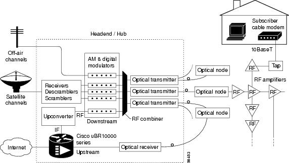
A Cisco uBR7200 series router and an intermediate frequency (IF)-to-radio frequency (RF) upconverter are installed at the headend or distribution hub to transmit digital data. The Cisco uBR7200 series router downstream ports transmit IF signals to the upconverter, which translates the downstream signals to RF for broadcast.
Receivers, scramblers, and descramblers then process the TV signals to encode or decode signals as needed for broadcast. Modulators format the analog TV and digital signals.
The analog and digital signals then pass through the RF combiner. The signals are broadcast from the headend through optical transmitters to fiber nodes.
Amplifiers, coaxial cable, and taps carry the signals to the subscriber premises. Signals are processed as follows:
•
•
–
Figure 1-1 illustrates this general signal flow and associated processes in the CMTS.
Figure 1-1 Two-Way Internet Access Network Example
Note
Recommended Basic Configuration for High-Speed Internet Access
The Cisco uBR7200 series router is fully capable of self-provisioning all CMs and hosts to which it is attached. The router supports multiple IP subnets, including different subnets for hosts and CMs. Configuration options are limited only by available configuration file length.
The Cisco uBR7200 series CMTS automatically connects DOCSIS-compliant CMs and hosts right out of the box. Therefore, the factory-supplied configuration activates the downstream RF to 861 MHz center frequency, and the upstream to 24 MHz.
Step 1
Note
Step 2
Basic Internet Access Sample Configuration File
General
The following sample configuration file for the Cisco uBR7200 series router includes the following features:
•
•
•
–
–
–
–
!version 12.1no service padservice timestamps debug uptimeservice timestamps log uptimeno service password-encryptionservice compress-configservice udp-small-servers max-servers 500!hostname uBR7200!boot system slot0:!no cable qos permission createno cable qos permission updatecable qos permission modemscable time-server!cable config-file platinum.cmservice-class 1 max-upstream 128service-class 1 guaranteed-upstream 10service-class 1 max-downstream 10000service-class 1 max-burst 1600cpe max 8timestamp!cable config-file gold.cmservice-class 1 max-upstream 64service-class 1 max-downstream 5000service-class 1 max-burst 1600cpe max 3timestamp!cable config-file silver.cmservice-class 1 max-upstream 64service-class 1 max-downstream 1000service-class 1 max-burst 1600cpe max 1timestamp!cable config-file disable.cmaccess-deniedservice-class 1 max-upstream 1service-class 1 max-downstream 1service-class 1 max-burst 1600cpe max 1timestamp!ip subnet-zeroip cefno ip domain-lookupip dhcp excluded-address 10.128.1.1 10.128.1.15ip dhcp excluded-address 10.254.1.1 10.254.1.15ip dhcp ping packets 1!ip dhcp pool CableModemsnetwork 10.128.1.0 255.255.255.0bootfile platinum.cmnext-server 10.128.1.1default-router 10.128.1.1option 128 ip 10.128.1.1option 4 ip 10.128.1.1option 2 hex ffff.8f80option 11 ip 10.128.1.1option 10 ip 10.128.1.1lease 1 0 10!ip dhcp pool hostsnetwork 10.254.1.0 255.255.255.0next-server 10.254.1.1default-router 10.254.1.1dns-server 10.254.1.1 10.128.1.1domain-name ExamplesDomainName.comlease 1 0 10!ip dhcp pool staticPC(012)host 10.254.1.12 255.255.255.0client-identifier 0108.0009.af34.e2client-name staticPC(012)lease infinite!ip dhcp pool goldmodemhost 10.128.1.129 255.255.255.0client-identifier 0100.1095.817f.66bootfile gold.cm!ip dhcp pool DisabledModem(0010.aaaa.0001)host 10.128.1.9 255.255.255.0client-identifier 0100.1095.817f.66bootfile disable.cm!ip dhcp pool DisabledModem(0000.bbbb.0000)client-identifier 0100.00bb.bb00.00host 10.128.1.10 255.255.255.0bootfile disable.cm!interface bundle 1ip address 5.102.0.1 255.255.0.0 secondaryip address 5.100.0.1 255.255.0.0cable arp filter request-send 3 2cable arp filter reply-accept 3 2no cable ip-multicast-echocable dhcp-giaddr primarycable helper-address 172.18.73.210!interface Cable5/0/0no ip addressno cable packet-cachecable bundle 1cable downstream channel-id 120cable downstream annex Bcable downstream modulation 256qamcable downstream interleave-depth 32cable downstream frequency 561000000no cable downstream rf-shutdowncable upstream max-ports 4cable upstream 0 connector 0cable upstream 0 frequency 24000000cable upstream 0 channel-width 3200000 3200000cable upstream 0 minislot-size 2cable upstream 0 power-level 0cable upstream 0 range-backoff 3 6cable upstream 0 modulation-profile 22no cable upstream 0 shutdown!ip classlessno ip forward-protocol udp netbios-nsip route 0.0.0.0 0.0.0.0 FastEthernet0/0ip http server!!alias exec scm show cable modemalias exec scf show cable flapalias exec scp show cable qos profile!line con 0transport input noneline aux 0line vty 0 4login!endThe command lines in the sample configuration file beginning with the cable modulation-profile command contain the critical elements necessary to set up a modulation profile in your overall configuration:
cable modulation-profile 22 request 0 16 0 22 qpsk scrambler 152 no-diff 32 fixedcable modulation-profile 22 initial 5 34 0 48 16qam scrambler 152 no-diff 392 fixedcable modulation-profile 22 station 5 34 0 48 16qam scrambler 152 no-diff 392 fixedcable modulation-profile 22 short 4 76 7 22 16qam scrambler 152 no-diff 128 shortenedcable modulation-profile 22 long 9 232 0 22 16qam scrambler 152 no-diff 128 shortenedIn this case, the user has configured modulation profile number "22" to be available to upstream channels wherever they are configured to apply it. Note that this modulation profile has been configured to operate with a QAM-16 modulation scheme. The default modulation scheme for any upstream profile (if it is not set to QAM-16) is QPSK.
Later in the configuration file example, upstream port 0 on the cable interface card installed in slot 5 uses the modulation profile configured in the sample:
cable upstream 0 modulation-profile 22