by William StallingsA network organizing technique that has come to recent prominence is the Software-Defined Network (SDN) [1]. In essence, an SDN separates the data and control functions of networking devices, such as routers, packet switches, and LAN switches, with a well-defined Application Programming Interface (API) between the two. In contrast, in most large enterprise networks, routers and other network devices encompass both data and control functions, making it difficult to adjust the network infrastructure and operation to large-scale addition of end systems, virtual machines, and virtual networks. In this article we examine the characteristics of an SDN, and then describe the OpenFlow specification, which is becoming the standard way of implementing an SDN. Evolving Network RequirementsBefore looking in more detail at SDNs, let us examine the evolving network requirements that lead to a demand for a flexible, response approach to controlling traffic flows within a network or the Internet. One key leading factor is the increasingly widespread use of Server Virtualization. In essence, server virtualization masks server resources, including the number and identity of individual physical servers, processors, and operating systems, from server users. This masking makes it possible to partition a single machine into multiple, independent servers, conserving hardware resources. It also makes it possible to migrate a server quickly from one machine to another for load balancing or for dynamic switchover in the case of machine failure. Server virtualization has become a central element in dealing with "big data" applications and in implementing cloud computing infrastructures. But it creates problems with traditional network architectures (for example, refer to [2]). One problem is configuring Virtual LANs (VLANs). Network managers need to make sure the VLAN used by the Virtual Machine is assigned to the same switch port as the physical server running the virtual machine. But with the virtual machine being movable, it is necessary to reconfigure the VLAN every time that a virtual server is moved. In general terms, to match the flexibility of server virtualization, the network manager needs to be able to dynamically add, drop, and change network resources and profiles. This process is difficult to do with conventional network switches, in which the control logic for each switch is co-located with the switching logic. Another effect of server virtualization is that traffic flows differ substantially from the traditional client-server model. Typically, there is a considerable amount of traffic among virtual servers, for such purposes as maintaining consistent images of the database and invoking security functions such as access control. These server-to-server flows change in location and intensity over time, demanding a flexible approach to managing network resources. Another factor leading to the need for rapid response in allocating network resources is the increasing use by employees of mobile devices such as smartphones, tablets, and notebooks to access enterprise resources. Network managers must be able to respond to rapidly changing resource, Quality of Service (QoS), and security requirements. Existing network infrastructures can respond to changing requirements for the management of traffic flows, providing differentiated QoS levels and security levels for individual flows, but the process can be very time-consuming if the enterprise network is large and/or involves network devices from multiple vendors. The network manager must configure each vendor's equipment separately, and adjust performance and security parameters on a per-session, per-application basis. In a large enterprise, every time a new virtual machine is brought up, it can take hours or even days for network managers to do the necessary reconfiguration [3]. This state of affairs has been compared to the mainframe era of computing [4]. In the era of the mainframe, applications, the operating system, and the hardware were vertically integrated and provided by a single vendor. All of these ingredients were proprietary and closed, leading to slow innovation. Today, most computer platforms use the x86 instruction set, and a variety of operating systems (Windows, Linux, or Mac OS) run on top of the hardware. The OS provides APIs that enable outside providers to develop applications, leading to rapid innovation and deployment. In a similar fashion, commercial networking devices have proprietary features and specialized control planes and hardware, all vertically integrated on the switch. As will be seen, the SDN architecture and the OpenFlow standard provide an open architecture in which control functions are separated from the network device and placed in accessible control servers. This setup enables the underlying infrastructure to be abstracted for applications and network services, enabling the network to be treated as a logical entity. SDN ArchitectureFigure 1 illustrates the logical structure of an SDN. A central controller performs all complex functions, including routing, naming, policy declaration, and security checks. This plane constitutes the SDN Control Plane, and consists of one or more SDN servers. 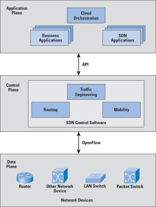
Figure 1: SDN Logical Structure The SDN Controller defines the data flows that occur in the SDN Data Plane. Each flow through the network must first get permission from the controller, which verifies that the communication is permissible by the network policy. If the controller allows a flow, it computes a route for the flow to take, and adds an entry for that flow in each of the switches along the path. With all complex functions subsumed by the controller, switches simply manage flow tables whose entries can be populated only by the controller. Communication between the controller and the switches uses a standardized protocol and API. Most commonly this interface is the OpenFlow specification, discussed subsequently. The SDN architecture is remarkably flexible; it can operate with different types of switches and at different protocol layers. SDN controllers and switches can be implemented for Ethernet switches (Layer 2), Internet routers (Layer 3), transport (Layer 4) switching, or application layer switching and routing. SDN relies on the common functions found on networking devices, which essentially involve forwarding packets based on some form of flow definition. In an SDN architecture, a switch performs the following functions:
In simple terms, the SDN controller manages the forwarding state of the switches in the SDN. This management is done through a vendor-neutral API that allows the controller to address a wide variety of operator requirements without changing any of the lower-level aspects of the network, including topology. With the decoupling of the control and data planes, SDN enables applications to deal with a single abstracted network device without concern for the details of how the device operates. Network applications see a single API to the controller. Thus it is possible to quickly create and deploy new applications to orchestrate network traffic flow to meet specific enterprise requirements for performance or security. SDN DomainsIn a large enterprise network, the deployment of a single controller to manage all network devices would prove unwieldy or undesirable. A more likely scenario is that the operator of a large enterprise or carrier network divides the whole network into numerous nonoverlapping SDN domains as shown in Figure 2. 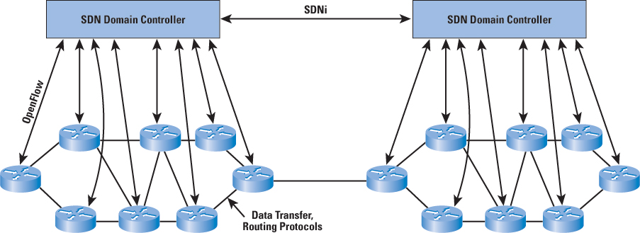
Figure 2: SDN Domain Structure Reasons for using SDN domains include the following:
The existence of multiple domains creates a requirement for individual controllers to communicate with each other via a standardized protocol to exchange routing information. The IETF is currently working on developing a protocol, called SDNi, for "interfacing SDN Domain Controllers" [5]. SDNi functions include:
The message types for SDNi tentatively include the following:
OpenFlowTo turn the concept of SND into practical implementation, two requirements must be met. First, there must be a common logical architecture in all switches, routers, and other network devices to be managed by an SDN controller. This logical architecture may be implemented in different ways on different vendor equipment and in different types of network devices, so long as the SDN controller sees a uniform logical switch function. Second, a standard, secure protocol is needed between the SDN controller and the network device. Both of these requirements are addressed by OpenFlow, which is both a protocol between SDN controllers and network devices, as well as a specification of the logical structure of the network switch functions [6, 7]. OpenFlow is defined in the OpenFlow Switch Specification, published by the Open Networking Foundation (ONF). ONF is a consortium of software providers, content delivery networks, and networking equipment vendors whose purpose is to promote software-defined networking. This discussion is based on the current OpenFlow specification, Version 1.3.0, June 25, 2012 [8]. The original specification, 1.0, was developed at Stanford University and was widely implemented. OpenFlow 1.2 was the first release from ONF after inheriting the project from Stanford. OpenFlow 1.3 significantly expands the functions of the specification. Version 1.3 is likely to become the stable base upon which future commercial implementations for OpenFlow will be built. ONF intends for this version to be a stable target for chip and software vendors, so little if any change is planned for the foreseeable future [9]. Logical Switch ArchitectureFigure 3 illustrates the basic structure of the OpenFlow environment. An SDN controller communicates with OpenFlow-compatible switches using the OpenFlow protocol running over the Secure Sockets Layer (SSL). Each switch connects to other OpenFlow switches and, possibly, to end-user devices that are the sources and destinations of packet flows. Within each switch, a series of tables—typically implemented in hardware or firmware—are used to manage the flows of packets through the switch. 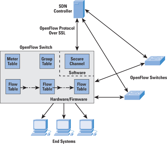
Figure 3: OpenFlow Switch The OpenFlow specification defines three types of tables in the logical switch architecture. A Flow Table matches incoming packets to a particular flow and specifies the functions that are to be performed on the packets. There may be multiple flow tables that operate in a pipeline fashion, as explained subsequently. A flow table may direct a flow to a Group Table, which may trigger a variety of actions that affect one or more flows. A Meter Table can trigger a variety of performance-related actions on a flow. Before proceeding, it is helpful to define what the term flow means. Curiously, this term is not defined in the OpenFlow specification, nor is there an attempt to define it in virtually all of the literature on OpenFlow. In general terms, a flow is a sequence of packets traversing a network that share a set of header field values. For example, a flow could consist of all packets with the same source and destination IP addresses, or all packets with the same VLAN identifier. We provide a more specific definition subsequently. Flow-Table ComponentsThe basic building block of the logical switch architecture is the flow table. Each packet that enters a switch passes through one or more flow tables. Each flow table contains entries consisting of six components:
A flow table may include a table-miss flow entry, which renders all Match Fields wildcards (every field is a match regardless of value) and has the lowest priority (priority 0). The Match Fields component of a table entry consists of the following required fields:
The preceding match fields must be supported by any OpenFlow-compliant switch. The following fields may be optionally supported:
Thus, OpenFlow can be used with network traffic involving a variety of protocols and network services. Note that at the MAC/link layer, only Ethernet is supported. Thus, OpenFlow as currently defined cannot control Layer 2 traffic over wireless networks. We can now offer a more precise definition of the term flow. From the point of view of an individual switch, a flow is a sequence of packets that matches a specific entry in a flow table. The definition is packet-oriented, in the sense that it is a function of the values of header fields of the packets that constitute the flow, and not a function of the path they follow through the network. A combination of flow entries on multiple switches defines a flow that is bound to a specific path. The instructions component of a table entry consists of a set of instructions that are executed if the packet matches the entry. Before describing the types of instructions, we need to define the terms "Action" and "Action Set." Actions describe packet forwarding, packet modification, and group table processing operations. The OpenFlow specification includes the following actions:
An Action Set is a list of actions associated with a packet that are accumulated while the packet is processed by each table and executed when the packet exits the processing pipeline. Instructions are of four types:
Flow-Table PipelineA switch includes one or more flow tables. If there is more than one flow table, they are organized as a pipeline as shown in Figure 4, with the tables labeled with increasing numbers starting with 0. 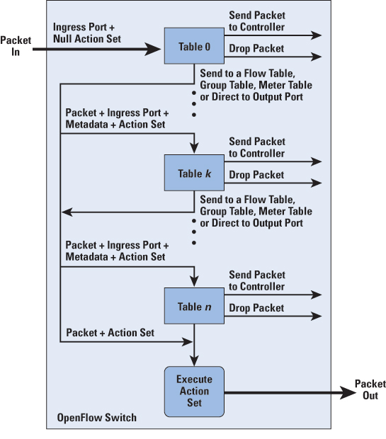
Figure 4: Packet Flow Through OpenFlow-Compliant Switch When a packet is presented to a table for matching, the input consists of the packet, the identity of the ingress port, the associated metadata value, and the associated action set. For Table 0, the metadata value is blank and the action set is null. Processing proceeds as follows:
For the final table in the pipeline, forwarding to another flow table is not an option. If and when a packet is finally directed to an output port, the accumulated action set is executed and then the packet is queued for output. OpenFlow ProtocolThe OpenFlow protocol describes message exchanges that take place between an OpenFlow controller and an OpenFlow switch. Typically, the protocol is implemented on top of SSL or Transport Layer Security (TLS), providing a secure OpenFlow channel. The OpenFlow protocol enables the controller to perform add, update, and delete actions to the flow entries in the flow tables. It supports three types of messages, as shown in Table 1.
Table 1: OpenFlow Messages
The OpenFlow protocol enables the controller to manage the logical structure of a switch, without regard to the details of how the switch implements the OpenFlow logical architecture. SummarySDNs, implemented using OpenFlow, provide a powerful, vendor-independent approach to managing complex networks with dynamic demands. The software-defined network can continue to use many of the useful network technologies already in place, such as virtual LANs and an MPLS infrastructure. SDNs and OpenFlow are likely to become commonplace in large carrier networks, cloud infrastructures, and other networks that support the use of big data. References[1] Greg Goth, "Software-Defined Networking Could Shake Up More than Packets," IEEE Internet Computing, July/August, 2011. [2] Robin Layland, "The Dark Side of Server Virtualization," Network World, July 7, 2010. [3] Open Networking Foundation, "Software-Defined Networking: The New Norm for Networks," ONF White Paper, April 12, 2012. [4] Dell, Inc., "Software Defined Networking: A Dell Point of View," Dell White Paper, October 2012. [5] Steven Vaughan-Nichols, "OpenFlow: The Next Generation of the Network?" Computer, August 2011. [6] Thomas A. Limoncelli, "OpenFlow: A Radical New Idea in Networking," Communications of the ACM, August 2012. [7] Open Networking Foundation, "OpenFlow Switch Specification Version 1.3.0," June 25, 2012. [8] Sean Michael Kerner, "OpenFlow Protocol 1.3.0 Approved," Enterprise Networking Planet, May 17, 2012. WILLIAM STALLINGS is an independent consultant and author of many books on security, computer networking, and computer architecture. His latest book is Data and Computer Communications (Pearson, 2013). He maintains a computer science resource site for computer science students and professionals at ComputerScienceStudent.com. He has a Ph.D. in computer science from M.I.T. He can be reached at ws@shore.net |
||||||||||||||||||||||||||||||||||||||
|
|
||||||||||||||||||||||||||||||||||||||