This document provides information on Cisco Systems, Inc. storage solution for Microsoft Exchange Server, based on the Microsoft Exchange Solution Reviewed Program (ESRP)-Storage program*. For any questions or comments regarding the contents of this document, see Contact for Additional Information.
*The ESRP-Storage program was developed by Microsoft Corporation to provide a common storage testing framework for vendors to provide information on its storage solutions for Microsoft Exchange Server software. For more details on the Microsoft ESRP-Storage program, please go to http://www.microsoft.com/technet/prodtechnol/exchange/2007/esrp.mspx.
Disclaimer
This document has been produced independently of Microsoft Corporation. Microsoft Corporation expressly disclaims responsibility for, and makes no warranty, express or implied, with respect to, the accuracy of the contents of this document.
The information contained in this document represents the current view of Cisco Systems, Inc. on the issues discussed as of the date of publication. Due to changing market conditions, it should not be interpreted to be a commitment on the part of Cisco Systems, Inc., and Cisco Systems, Inc. cannot guarantee the accuracy of any information presented after the date of publication.
Cisco Unified Computing System
Today's data center managers are faced with the arduous task of reducing expenses while increasing responsiveness. Finding ways to better address rising data center capital and operations costs has companies pursuing strategies such as infrastructure consolidation and virtualization. Although this continues to offer dramatic increases in server utilization, virtualization alone is not the answer. In fact, the increase in virtual machines is driving the need for more software, networking and storage resources that are increasing costs and adding complexity within the data center. At the same time, companies are looking for architectures and solutions that will allow them to improve their service delivery capabilities. The industry is transitioning away from the rigid, inflexible platforms and moving toward more flexible, integrated, and virtualized environments. Cisco's Unified Computing System (UCS) was designed from the ground up to specifically meet these challenges.
Cisco UCS Solution
Cisco® UCS C-Series Rack-Mount Servers extend unified computing innovations to an industry-standard form factor to help reduce total cost of ownership (TCO) and increase business agility. Designed to operate both in standalone environments and as part of the Cisco Unified Computing System™, the series employs Cisco technology to help customers handle the most challenging workloads. The series incorporates a standards-based unified network fabric and Cisco VN-Link virtualization and protects customer investments with a future migration path to unified computing.
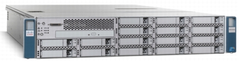
The Cisco UCS C210 M2 General-Purpose Rack-Mount Server is a two-socket, two-rack-unit (2RU) rack-mount server housing up to 16 internal small form-factor (SFF) SAS, SATA or SSD drives for a total of up to 16 terabytes (TB) of storage (Figure 1). The Cisco UCS C210 M2 server is designed to balance performance, density, and efficiency for workloads requiring economical, high-capacity, reliable, internal storage. Based on six-core Intel® Xeon® 5600 series processors, the server is built for applications including virtualization, network file servers and appliances, storage servers, database servers, and content-delivery servers.
Building on the success of the Cisco UCS C210 M1 General-Purpose Rack-Mount Server, the Cisco UCS C210 M2 server (Figure 1) extends the capabilities of the Cisco Unified Computing System with the next generation of Intel processor technology: Intel® Xeon® 5600 series processors. These powerful processors deliver more cores, threads, and cache, all within a similar power envelope, with even faster payback, greater productivity, and better energy efficiency than preceding models. When put into production, Cisco Unified Computing System and Intel Xeon 5600 series processors together offer further reductions in TCO, increased business agility, and another big leap forward in data center virtualization.
Figure 1. Cisco UCS C210 M2 Rack-Mount Server
The Cisco UCS C210 M2 server extends Cisco's product portfolio to meet the needs of customers that choose to deploy rack-mount servers. The server enables organizations to deploy systems incrementally, using as many or as few servers as needed, on a schedule that best meets the organization's timing and budget.
Designed to operate both in standalone environments and as part of the Cisco Unified Computing System, the server combines high-capacity disk storage and I/O configurations with Cisco innovations, including a unified network fabric and network-aware Cisco VN-Link technology.
The server brings differentiation and value to what has been a commodity market with products not optimized to meet the needs of virtualized data centers. Available from Cisco and its data center network infrastructure (DCNI) partners, the server advances the rack-mount server market with the features outlined in Table 1.
Table 1. Features and Benefits
Feature
Benefit
10-Gbps unified network fabric
• Low-latency, lossless, 10-Gbps Ethernet and industry-standard Fibre Channel over Ethernet (FCoE) fabric
• Wire-once deployment model in which changing I/O configurations no longer means installing adapters and recabling racks and switches
• Fewer interface cards, cables, and upstream network ports to purchase, power, configure, and maintain
Virtualization optimization
• Cisco VN-Link technology, I/O virtualization, and Intel Xeon 5600 series processor features, extending the network directly to virtual machines
• Consistent and scalable operational model
• Increased security and efficiency with reduced complexity
Unified management*
(when integrated into the Cisco Unified Computing System)
• Entire solution managed as a single entity with Cisco UCS Manager, improving operational efficiency and flexibility
• Service profiles and templates that implement role- and policy-based management, enabling more effective use of skilled server, network, and storage administrators
• Automated provisioning and increased business agility, allowing data center managers to provision applications in minutes rather than days
Six-core Intel Xeon 5600 series processors
• Intelligent performance that automatically adjusts processor performance to meet application demands, increasing performance when needed and achieving substantial energy savings when not
• Automated energy efficiency that reduces energy costs by automatically putting the processor and memory in the lowest available power state while still delivering the performance required
• Flexible virtualization technology that optimizes performance for virtualized environments, including processor support for migration and direct I/O
• With more cores, threads, and cache, in a similar power envelope, the Cisco Unified Computing System and Intel Xeon 5600 series processors together offer further reductions in TCO, increased business agility, and another big leap forward in data center virtualization.
• Cisco C-series servers keep pace with Intel Xeon processor innovation by offering the latest series 5600 processors with an increase in processor frequency and improved security features. With the increased clock speed, the Intel Xeon 5600 series based UCS C-Series rack mount servers will offer improved price/performance making UCS servers one of the best values in the industry.
High-capacity, flexible internal storage
• Up to 16 front-accessible, hot-swappable, SFF SAS, SATA or SSD drives for local storage, providing redundancy options and ease of serviceability
• Balanced performance and capacity to best meet application needs:
• 15,000 RPM SAS drives for highest performance
• 10,000 RPM SAS drives for high performance and value
• 7200-RPM SATA drives for high capacity and value
RAID 0, 1, 5, 6, 10, 50, and 60 support
A choice of RAID controllers to provide data protection for up to 16 SAS, SATA or SSD drives in PCIe and mezzanine card form factors
Cisco UCS Integrated Management Controller
• Web user interface for server management; remote keyboard, video, and mouse (KVM); virtual media; and administration
• Virtual media support for remote KVM and CD and DVD drives as if local
• Intelligent Platform Management Interface (IPMI) 2.0 support for out-of-band management through third-party enterprise management systems
• Command-line interface (CLI) for server management
Fast-memory support
12 DIMM slots supporting up to 192 GB of 1333-MHz memory for optimal performance
Redundant fans and power supplies
Dual-redundant fans and power supplies for enterprise-class reliability and uptime
5 PCI Express (PCIe) 2.0 slots
• Flexibility, increased performance, and compatibility with industry standards
• PCIe 2.0 slots, which double bandwidth over the previous generation and offer more flexibility while maintaining compatibility with PCIe 1
• I/O performance and flexibility with 2 full-height, full-length and 3 full-height half-length x8 PCIe slots, all with x16 connectors
Integrated dual-port Gigabit Ethernet
• Outstanding network I/O performance and increased network efficiency and flexibility.
• Increased network availability when configured in failover configurations
Optional optical drive
Direct front-panel read/write access to CD and DVD media
Solution Description
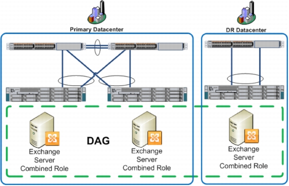
The tested solution (Figure 2) provides a highly available Exchange 2010 deployment for 2500 mailbox users. Each Exchange server runs the combined Mailbox, Client Access Server, and Hub Transport roles on Cisco C210 M2 rack mount servers. The Cisco C210 M2 rack mount servers are efficient, occupying only 2 RU of rack space. The primary datacenter has two Exchange servers in a Data Availability Group. The Data Availability Group uses continuous replication to replicate mailbox database data between member servers. During normal operation each Exchange server runs 1250 active mailboxes.
If one of the two Exchange servers in the primary datacenter needs to be taken offline or fails, the surviving Exchange server is capable of servicing all 2500 mailboxes without noticeable service degradation. The Client Access Server and Hub Transport server roles, which run on each exchange server, are also redundant and are capable of sustaining the entire workload during peak work hours without noticeable service degradation.
Figure 2. Solution Architecture
The test was conducted on a C210 M2 Cisco UCS Server, firmware version 1.4 (1a), Bios Version: C200 1.4.1.0 (BuildDate 07/13/2011). The server is powered by two (2) 6-Core 12 thread Xeon E5649@2.53Ghz CPUs and contains 48Gb (6 x 8192MB Synchronous DIMMs) 1333mhz RAM. The storage adaptor used to create the RAID 1, and RAID 10 Storage Volumes is an LSI MegaRAID SAS 9261-8i with 512 MB Cache.
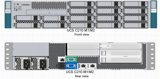
Figure 3. Cisco UCS C210 M1/M2 Front and Back View
The two drive RAID 1 solution for the system drive is illustrated in Figure 3. RAID 1 was created using the RAID controller's WebBios screen which can be accessed during the boot up process using the Ctrl+H keystroke.
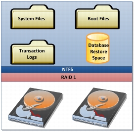
Figure 4. RAID 1 Solution
For additional information regarding the RAID Controller configuration and Cisco UCS C210 configuration options, please refer to:
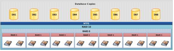
The 14 drive RAID 10 solution for the data drive is illustrated in Figure 4. The drives are configured within the controller as 7 spans of mirrors (RAID 1) with a stripe throughout the spans (RAID 0). The result is RAID 10 (1+0) redundancy for the drive that houses the database.
Figure 5. RAID 10 Solution
The following links will aid in visualizing the provided solution:
The ESRP-Storage program focuses on storage solution testing to address performance and reliability issues with storage design. However, storage is not the only factor to take into consideration when designing a scale up Exchange solution. Other factors that affect the server scalability are:
• Server processor utilization
• Server physical and virtual memory limitations
• Resource requirements for other applications
• Directory and network service latencies
• Network infrastructure limitations
• Replication and recovery requirements
• Client usage profiles
All these factors are beyond the scope for ESRP-Storage. Therefore, the number of mailboxes hosted per server as part of the tested configuration may not necessarily be viable for some customer deployments. For more information on identifying and addressing performance bottlenecks in an Exchange system, please refer to Microsoft's Troubleshooting Microsoft Exchange Server Performance http://technet.microsoft.com/en-us/library/dd335215.aspx.
Targeted Customer Profile
This solution is intended for small-to-medium sized organizations:
• 2500 Mailboxes
• One Host attached to storage system
• Mailbox Resiliency = Data Availability Group (DAG)
• Three Database Copies Per Server
• Mailbox quota: 1352 MB per mailbox
• User IO profile: 0.18 IOPS per mailbox
• 24x7 Background Database Maintenance utilized
• Eight Databases per server
Tested Deployment
The following tables summarize the testing environment:
Table 2. Simulated Exchange Configuration
Number of Exchange mailboxes simulated
2500
Number of Database Availability Groups (DAGs)
1
Number of servers/DAG
1
Number of active mailboxes/server
2500
Number of databases/host
8
Number of copies/database
3
Number of mailboxes/database
312
Simulated profile: I/O's per second per mailbox (IOPS, include 20 percent headroom)
.18
Database LUN size
6512.61 GB
Log LUN size
930gb
Total database size for performance testing
3296gb
% storage capacity used by Exchange database**
44.29%=(3296gb/7442gb)
**Storage performance characteristics change based on the percentage utilization of the individual disks. Tests that use a small percentage of the storage (~25%) may exhibit reduced throughput if the storage capacity utilization is significantly increased beyond what is tested in this paper.
LSI 9261-8i MegaRAID SAS HBA Firmware Version: 2.12-.133-1322
Number of HBA's/host
N/A
Host server type
Two (2) 6-Core 12 thread Xeon E5649@2.53Ghz CPUs and contains 48Gb (12 x 8192MB Synchronous DIMMs) 1067mhz RAM
Total number of disks tested in solution
16
Maximum number of spindles can be hosted in the storage
16
Table 4. Storage Software
HBA driver
MEGASAS Storport Driver for Windows 7\Server 2008 R2 for x64 megasas2.sys 4.32.0.64
HBA QueueTarget Setting
N/A
HBA QueueDepth Setting
N/A
Multi-Pathing
N/A
Host OS
Windows 2008R2 Enterprise SP1
ESE.dll file version
14.1.218.12
Replication solution name/version
N/A
Table 5. Storage Disk Configuration (Mailbox Store Disks)
Disk type, speed and firmware revision
Seagate 1TB 7.2K RPM SATA ST91000640NS 2.5" 1 TB Drives
Raw capacity per disk (GB)
931.513
Number of physical disks in test
14
Total raw storage capacity (GB)
13041.182
Disk slice size (GB)
N/A
Number of slices per LUN or number of disks per LUN
N/A
RAID level
RAID 10
Total formatted capacity
6512.61 GB
Storage capacity utilization
6512.61/13041.182=49.93%
Database capacity utilization
4152/13041.182=31.84%
Table 6. Storage Disk Configuration (Transactional Log Disks)
Disk type, speed and firmware revision
Seagate 1TB 7.2K RPM SATA ST91000640NS 2.5" 1 TB Drives
Raw capacity per disk (GB)
931.513
Number of Spindles in test
1
Total raw storage capacity (GB)
931.513
Disk slice size (GB)
N/A
Number of slices per LUN or number of disks per LUN
N/A
RAID level
RAID 1
Total formatted capacity
930.29 GB
Best Practices
Set up the system using the following table as a guide.
Table 7. Guide for Best Practices
Drive Type
Drive Letter
Raid Type
Format
System Drive
Drive C:
Raid 1
Contains Operating System and Log Files; format as NTFS; 64K disk allocation size
Data Drive
Drive F:
Raid 10
Format as GPT drive. Contains Database; 64K disk allocation size
The outlined design fulfills the capacity and performance needs for 2500 users, each with a Mailbox limit of 1352 MB. The user profile of 0.18 IOPS per mailbox includes a margin for 20 percent overhead.
Exchange server 2010 is a disk I/O intensive application. Tests were conducted using the Microsoft tool Jetstress 2010, 14.01.0225.017.
Install current firmware and device drivers for all devices in the server, such as network adapters, even if the device will not be used in the configuration. Current Cisco C210 M2 firmware and device drivers for Windows can be found on the UCS Server Firmware ISO and the UCS Drivers ISO. Both can be downloaded from www.cisco.com.
The following practices will help improve the I/O subsystem performance:
• Exchange 2010 is an IO intensive application. Do not share Exchange 2010 storage resources with other applications as performance may be negatively impacted.
• Store the Exchange databases and transaction logs on separate NTFS drive volumes. The Exchange Server 2010 resiliency solution no longer requires separate spindles for log and database files. However, placing the databases on a dedicated NTFS drive and the transaction logs on the system drive allows more space for Exchange databases and enables the deployment of larger mailboxes.
• Windows NTFS allocation unit size for Exchange 2010 database partitions should be set to 64K disk allocation size.
• Exchange Server 2010 storage latencies are related to the number of disks available for a given workload. Windows Performance Monitor may be used to monitor Exchange Server 2010 database counters. Average database read latencies (Avg. Disk sec/Read) should not exceed 20ms.
• Choose Enterprise class SATA disks for storage considerations as storage/design requirements indicate high capacity, moderate performance, and moderate power utilization and SATA storage has very good heat, vibration, and reliability characteristics. The disks used in this test are Seagate Constellation ST91000640N 2.5 inch, 7200 RPM, 1TB SATA drives.
• Windows Server 2008 R2 does not require the use of diskpart.exe to define sector boundary alignment as Window Server 2003 did since the sector boundaries are created automatically. Logical volumes are created using the Windows logical disk manager during the setup phase of the OS installation. Also, using Windows 2008R2 setup, the disk partitions are created with an automatic 1 MB offset (except when the disk capacity is less than 4 GB).
• Format the Database RAID 10 Array as a GPT disk if it is larger than 2TB. In this case, the 14 1TB RAID 10 disks yield approximately 7TB, and a GPT format is recommended.
RAID Controller best practices are to create a 256K strip size on the arrays and then enable read ahead, writeback, direct IO, Drive Cache disable, and Disable BGI parameters. Refer to the following table:
Table 8. RAID Controller Best Practices
Parameter
Value
Strip Size
256
Access Policy
RW
Read Policy
Ahead
Write Policy
WBack
IO Policy
Direct
Drive Cache
Disable
Disable BGI
No
Create the System Drive so that it will contain Windows 2008 R2 SP1 Enterprise using RAID 1 (2 spindles) and the Data Drive holding the Jetstress database using RAID 10 (14 spindles). Point the WebBrowser to the UCS C210 Server by entering its IP address and within the Cisco UCS Console, open the KVM, exercise the Ctrl+Alt+Del Macro from the file menu and while the host computer is booting press CTRL+H at the following screen in order to enter the RAID bios menu:
The tests performed for backup are: backup-to-disk (read only) and log replay. The backup-to-disk test measures the read I/O performance by running a checksum on all the databases and log files. This test can help determine the level of database read throughput that can be achieved during backups. The backup speed and throughput achieved will depend upon the backup device used. The log replay test was used to measure the maximum rate at which the log files can be played against the databases. This is used to determine the restore times and the database write throughput that can be achieved during a log recovery.
To learn more about running Microsoft Enterprise Applications on Cisco Unified Computing System, please visit: http://www.cisco.com/go/microsoft.
Test Results Summary
This section provides a high level summary of the test data from ESRP and the link to the detailed html reports which are generated by ESRP testing framework. Please click the underlined headings below to view the HTML report for each test.
Reliability
A number of tests in the framework will check 24 hour Reliability tests runs. The goal is to verify that the storage can handle high IO load for a long period of time. Both log and database files were analyzed for integrity after the stress test to help ensure that there was no database/log corruption.
The following list provides an overview:
• Any errors reported in the saved eventlog file? No
• Any errors reported during the database and log checksum process? No
• If backup to disk test is done, any errors reported during the process? No
• Any errors during database checksum on the remote storage database? N/A
Storage Performance Results
The Primary Storage performance test is designed to exercise the storage simulating maximum sustainable Exchange type of IO for two hours. The test measures the length of time needed for the storage subsystem to respond to an IO under load. The data below is the sum of all of the logical disk I/O's and average of all the logical disks I/O latency in the two hours test duration. Each server is listed separately and the aggregate numbers across all servers are listed as well
Individual Performance Across All Servers Metrics
The sum of I/O's across all servers in the solution including their average latency.
Database I/O
Database Disks Transfers/sec
651.699
Database Disks Reads/sec
370.981
Database Disks Writes/sec
280.717
Average Database Disk Read Latency (ms)
14.580
Average Database Disk Write Latency (ms)
1.342
Transaction Log I/O
Log Disks Writes/sec
248.284
Average Log Disk Write Latency (ms)
1.065
Database Backup/Recover Performance
There are two tests reports in this section. The first one measures the sequential read rate of the database files, and the second measures the recovery/replay performance (playing transaction logs in to the database).
Database Read-Only Performance
This test measures the maximum rate at which databases can be backed up through VSS. The following table shows the average rate for a single database file.
MB read/sec per database
30.846
MB read/sec total per server
246.77
Transaction Log Recovery/Replay Performance
This test measures the maximum rate at which the log files can be played against the databases. The following table shows the average rate for 500 log files played in a single storage group. Each log file is 1 MB in size.
Average time to play one Log file (sec)
2.8426
Conclusion
Our tests, outlined in this document, illustrate the fact that the Cisco UCS C210 M2 system is an excellent platform for provisioning an Exchange Resiliency 2010 Storage Solution. The tests clearly show that 2500 Exchange users have ample resources within a Cisco UCS system containing:
• Dual Xeon 6-core 12 thread 5649@2.53Ghz CPUs
• 48Gb (12 x 8192MB Synchronous DIMMs) 1067mhz RAM
To maintain the IOPs required by a Microsoft Exchange Resiliency solution as well as needed reserve to support continuous and uninterrupted use.
This document was developed by Cisco and reviewed by Microsoft Exchange Product team. The test results/data presented in this document are based on the tests introduced in the ESRP test framework. Customer should not quote the data directly for their pre-deployment verification. It is still necessary to go through the exercises to validate the storage design for a specific customer environment.
The ESRP program is not designed to be a benchmarking program--tests are not designed to get the maximum throughput for a given solution. Instead, ESRP is focused on producing recommendations from vendors for Exchange application. Therefore, the data presented in this document should not be used for direct comparisons among the solutions.
Appendix A: Stress Testing
Stress Test Result Report
Test Summary
Overall Test Result
Pass
Machine Name
EXCHANGE1
Test Description
Create New Config 3 threads, .18 iops, 1352mb mailbox, 2500 users 48gb RAM Test
Test Start Time
5/29/2012 10:12:53 AM
Test End Time
5/30/2012 10:17:44 AM
Collection Start Time
5/29/2012 10:17:24 AM
Collection End Time
5/30/2012 10:17:21 AM
Jetstress Version
14.01.0225.017
ESE Version
14.02.0247.001
Operating System
Windows Server 2008 R2 Enterprise Service Pack 1 (6.1.7601.65536)