This document provides a technical overview of power, space, and cooling considerations required for successful deployment of IT equipment in the data center. Topics are introduced with a high-level conceptual discussion and then discussed in the context of Cisco® products.
The Cisco Unified Computing System™ (Cisco UCS™) product line works with industry-standard rack and power solutions generally available for the data center. Cisco also offers racks and power distribution units (PDUs) that have been tested with Cisco UCS and selected Cisco Nexus® products.
This document is intended to inform those tasked with physical deployment of IT equipment in the data center. This document does not discuss equipment configuration or deployment from the viewpoint of a system administrator.
Data Center Thermal Considerations
Cooling is a major cost factor in data centers. If cooling is implemented poorly, the power required to cool a data center can match or exceed the power used to run the IT equipment itself. Cooling also is often the limiting factor in data center capacity (heat removal can be a bigger problem than getting power to the equipment).
Table 1 lists the recommended operating range for temperature and humidity.
Table 1. Recommended Temperature Ranges
Low-end temperature
64.4°F (18°C)
High-end temperature
80.6°F (27°C)
Low-end moisture
40% relative humidity and 41.9°F (5.5°C) dew point
High-end moisture
60% relative humidity and 59°F (15°C) dew point
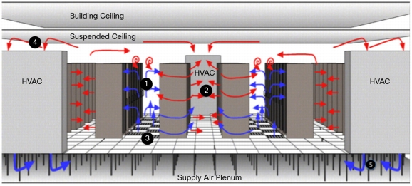
These temperatures specifically describe the IT equipment intake temperature. However, there are several locations in the data center where the environment can be measured and controlled. These points include:
• Server inlet (point 1 in Figure 1)
• Server exhaust (point 2 in Figure 1)
• Floor tile supply temperature (point 3 in Figure 1)
• Heating, ventilation, and air conditioning (HVAC) unit return air temperature (point 4 in Figure 1)
• Computer room air conditioning unit supply temperature (point 5 in Figure 1)
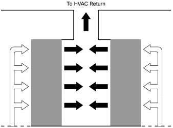
Figure 1. Data Center Temperature Flow
Typically, data center HVAC units are controlled based on return air temperature (point 4 in Figure 1). Setting the HVAC unit return air temperatures to match the ASHRAE requirements will result in very low server inlet temperatures, because HVAC return temperatures are closer to server exhaust temperatures than inlet temperatures.
The lower the air supply temperature in the data center, the greater the cooling costs. In essence, the air conditioning system in the data center is a refrigeration system. The cooling system moves heat generated in the cool data center into the outside ambient environment. The power requirements for cooling a data center depend on the amount of heat being removed (the amount of IT equipment you have) and the temperature delta between the data center and the outside air.
The rack arrangement on the data center raised floor can also have a significant impact on cooling-related energy costs and capacity, as summarized in the next section.
Best Practices
Although this document is not intended to be a complete guide for data center design, this section presents some basic principles and best practices of data center airflow management.
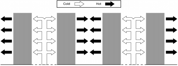
Hot-Aisle and Cold-Aisle Layout
The hot-aisle and cold-aisle layout in the data center has become a standard (Figure 2). By arranging the rack into rows of hot and cold aisles, the mixing of air in the data center is minimized. If warm air is allowed to mix with the server inlet air, the air supplied by the air conditioning system must be supplied at an even colder supply temperature to compensate. As described earlier, lower cooling air supply temperatures cause increased energy use by the chiller and limit the cooling capacity of the data center by creating hot spots.
Figure 2. Hot-Aisle and Cold-Aisle Layout
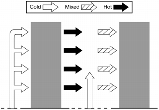
In contrast, not using segregated hot and cold aisles results in server inlet air mixing. Air must be supplied from the floor tile at a lower temperature to meet the server inlet requirements, as shown in Figure 3.
Figure 3. Server Inlet Air Mixing
Populating the Rack
Racks should be populated with the heaviest and most power-dense equipment at the bottom. Placing heavy equipment at the bottom helps lower the racks center of mass and helps reduce the risk of tipping. Power-dense equipment also tends to draw more air. In the typical data center, in which air is supplied through perforated floor tiles, placing power-dense equipment near the bottom of the rack gives that equipment the best access to the coldest air.
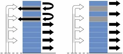
Unoccupied space in the rack can also cause hot air penetration back into the cold aisle. Blanking panels are a simple measure that can be used to prevent this problem, as shown in Figure 4.
Figure 4. Blanking Panels
In summary, populate racks from the bottom up and fill any gaps between hardware or at the top of the rack with blanking panels.
Containment Solutions
An effective extension of the hot- and cold-aisle concept is airflow containment. Figure 5 depicts hot-aisle containment. Containment provides complete segregation of the hot and cold air streams, which has the benefit of reducing energy use in the HVAC system by allowing the temperature of the cold air output to be raised. Because there is no mixing of air, there is no need to set the air temperature lower to compensate. This approach also increases the temperature of the air returning to the HVAC system, which also helps improve the efficiency of the HVAC system.
For hot-aisle containment, care should be taken to not create pressure in the hot aisle. IT systems are designed so that they have a near zero pressure difference between their air intake and exhaust. Backpressure in the hot aisle can cause fans to work harder in the system.
Cold-aisle containment (not shown here) is another option.
Figure 5. Airflow Containment
Cable Management
To the greatest extent possible, airflow obstructions should be removed from the intake and exhaust openings of the equipment mounted in the chassis. Lack of sufficient airflow may result in increased equipment fan power consumption to compensate for increased airflow impedance. If a rack door is installed, it should be perforated and be at least 65 percent open. Solid doors, made of glass or any other material, inevitably result in airflow problems and should be avoided. Please consult the hardware installation guide for specific equipment requirements.
Proper cable management is critical to reducing airflow blockage. By using Cisco UCS, you can significantly reduce the number of networking cables required. However, it is still important to properly dress the cables to provide the best airflow, as shown in Figure 6.
Figure 6. Properly Dressed Cables
Relationship Between Heat and Power
All power that is consumed by IT equipment is converted to heat. Though power is typically reported in watts (W) and heat is typically reported in British thermal units (BTUs) per hour (BTU/hr), these units are in fact interchangeable. Although power is almost always reported in watts, heat load is sometimes reported in watts and sometimes in BTU/hr. The conversion from watts to BTU/hr is 1W = 3.412 BTU/hr. So, for example, a server that consumes 100W produces approximately 341.2 BTU/hr of heat.
Energy Savings in Cisco's Facilities
To carefully study the effects of best practices to promote energy efficiency, Cisco underwent a data center efficiency study in the Cisco research and development laboratories between October 2009 and April 2010. As part of this study, the following best practices were applied:
• Redundant power was disabled where possible
• Power savings programs were used
• Computational fluid dynamics modeling (CFD) was used
• Virtualization was applied
• Blanking panels were used
• The floor grill was rearranged
• The chilled water temperature was raised from 44°F to 48°F (7°C to 9°C)
This study demonstrated major improvements in data center power and cooling efficiency. Even though an increase in hardware installations caused the IT load to increase slightly (from 1719 to 1761 kilowatts [kW]), the overhead for cooling the data center dropped (from 801 to 697 kW). The overall power usage effectiveness (PUE) dropped from 1.48 to 1.36. The payback from the proof of concept was 6 to 12 months. The ideas from this pilot project are being applied to all Cisco facilities and are projected to save US$2 million per year.
Cisco Rack Solutions
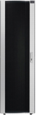
The Cisco R42610 Rack is an industry-standard (EIA-310-D), 19-inch rack that has been tested and certified for use with Cisco UCS and selected Cisco Nexus products. The complete list of products that have been tested with Cisco R Series Racks is maintained on an internal Cisco website. Please contact your Cisco representative to access the latest information.
Table 2 lists the main features and benefits of Cisco R Series Racks. Table 3 lists rack dimensions.
Table 2. Main Features and Benefits of Cisco R Series Racks
Feature
Benefit
Tested with Cisco UCS
• Industry-standard, EIA-310-D racks have been optimized for Cisco UCS
• Standard and expansion racks are ideal for single-rack or multiple-rack Cisco UCS deployments
Front and rear doors
• 80% perforation on front and rear doors increase airflow
• Locks are included for added security
• Toolless door removal enables convenient servicing
• Split rear doors reduce the clearance required at the rear of the rack
• Adjustable front door can swing from right to left or left to right
Split side panels
• Lightweight, 2-piece side panels are easy to install and remove
• Locks provide additional security
Top panel
• Ventilated top panel has optional cutouts for a large cable egress
PDU mounting
• Sidewall spaces and PDU trays allow quick installation of zero-rack-unit (0RU) and 1RU PDUs
• Integrated PDU trays enable toolless mounting for optional 0RU Cisco RP Series PDUs
Other
• Front and side stabilizer brackets are included with rack
• Joining kit option connects adjacent expansion racks within a row
• Casters permit greater mobility
• Removable rear cable access bar accelerates cable routing
• RU markings on rack rails simplify equipment installation
• UL 60950.1, CAN/CSA C22.2 No. 60950-1-03, and RoHS compliance meets regulatory requirements
Table 3. Cisco Rack Dimensions
Cisco R42610 Rack
Standard
Expansion
Dimensions (H x W x D)
78.74 x 24 x 43.38 in.
(2000 x 610 x 1102 mm)
78.74 x 23.58 x 43.38 in.
(2000 x 599 x 1102 mm)
Dimensions (H x W x D) with packaging
89 x 33 x 47 in.
(2261 x 838 x 1194 mm)
89 x 33 x 47 in.
(2261 x 838 x 1194 mm)
Rail kit length (front to back)
29 in.
(737 mm)
29 in.
(737 mm)
Weight with packaging
354 lb (161 kg)
284 lb (129 kg)
Side panels included
Yes
No
Equipment mounting capacity
42RU
42RU
Static load capacity
2100 lb (954 kg)
2100 lb (954 kg)
Dynamic load capacity
-
-
Cisco Rack Options and Descriptions
Optimizing airflow through the Cisco rack involves eliminating bypass air and helping ensure proper cable management. The Cisco rack solution has options to help. Proper care should be taken to eliminate mixing of hot and cold air. Similarly, proper cable management should be used to reduce airflow impedance.
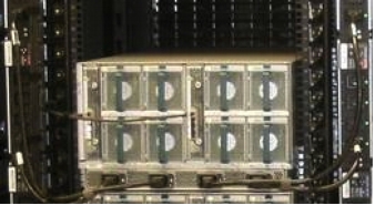
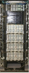
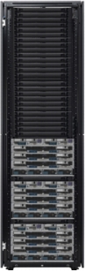
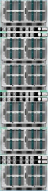
Figure 7 shows the Cisco R42610 Rack populated with three Cisco UCS 5108 Blade Server Chassis. Empty slots at the top of the rack are filled in with blanking panels. Empty rack units between chassis also are populated with blanking panels.
Figure 7. Cisco R42610 Rack Populated with Three Cisco UCS 5108 Chassis
Multi-Rack Deployment Solutions
The standard Cisco R42610 Rack is ideal for single-rack deployments because it comes with side panels.
Multi-rack deployments require special consideration. Since rows are typically arranged with racks side by side, side panels are not necessary for racks in the interior of the row. The suggested approach is to order one standard rack and then order expansion racks for the rest of the racks in the row. The side panels from the standard rack can be used to cover the exposed sides of the racks at the end of the row.
Adjacent racks can be physically attached to one another through the optional rack joining kit. The specific part number is listed in Table 4. Figure 8 shows two racks connected by a joining kit.
Optionally, racks can be bolted to the floor to prevent them from shifting position. An additional stabilizing kit can be ordered to bolt both the front and the back of the rack to the floor.
Power delivery at the facility level requires careful planning. Thorough power planning requires an understanding of server power consumption and redundancy requirements. Poor redundancy planning can result in cascading failures and downtime.
Overview
The proper deployment of power solutions in the data center involves matching the requirements of the IT equipment to the capabilities of the PDU and the facility. Good power planning follows these steps:
• Step 1: Gather the IT equipment power requirements.
– Power redundancy
– Number of required power receptacles (number of required power connections between the server and the PDU)
– Power capacity
• Step 2: Gather the facility power and cooling parameters. This step involves gathering some basic information about the data center:
– What voltage is used?
– Is power available as single phase or three phase?
– What is type of facility power plugs are used?
– How much cooling is available?
• Step 3: Design the PDU solution. The PDU is what connects the IT equipment and the power source in the data center. After the facility parameters and the IT equipment parameters are defined, the PDU solution can be designed. This step involves making sure the demands of the IT equipment match the capabilities of the facility. It also involves checking that the solution delivers the proper redundancy.
Power Planning
The process described here assumes that the customer first decides how many servers to install per rack and then designs the facility around the rack. Often, however, facility requirements guide the IT solution design. In this case, the process may need to proceed iteratively. For example, if the IT equipment demands cannot be met with the capabilities of the facility, the amount of equipment deployed per rack may need to be reduced.
Step 1: Gather the IT Equipment Power Requirements
Requirement 1: Power Redundancy
The first step in sizing a PDU solution is deciding what type of redundancy the end user requires. Clearly, true AC grid redundancy forces requirements on the facility itself because it requires separate and independent AC power sources to be supplied to the racks in the data center. However, redundancy levels also dictate the number of power supplies installed in the equipment itself and hence the number of power plugs required.
In determining the number of PDUs and power sockets required, some background terminology will be helpful:
• Non-redundant power (N): The device being powered is fed power from a single AC power source and is equipped with the minimum number of power supplies. Downtime may result from the loss of a power supply or the loss of a utility feed.
• N+1 redundancy (N+1): The device being powered receives power from a single AC power source but is equipped with at least one redundant power supply. Loss of a utility feed results in downtime, but the device can tolerate the loss of at least one power supply.
• Grid redundancy (2N): The device being powered is equipped with twice the required number of power supplies. To maintain true grid redundancy, half the power supplies should derive power from one AC power source, and the other half should be connected to a separate, independent AC power source. 2N redundancy allows the system to tolerate the loss of any power supply or a single AC power source.
In general, full 2N grid redundancy requires double the number of PDUs needed for single grid power deployment without any power supply redundancy. To have true grid redundancy, each independent AC power source must be provisioned with enough capacity to carry the full load. While both AC power sources are online, the load may be shared between the input sources. Load sharing of the installed devices will cause each feed to appear to have a light load. However, if one of the input power sources fails, the result is an instantaneous spike in power on the remaining source. If each power source is not sized to carry the full, expected load, then the loss of a redundant feed may cause the remaining feed to become overloaded and result in downtime through cascading failures.
Requirement 2: Number of Required Power Receptacles
In general, the minimum number of required PDU power sockets for a rack-level PDU solution depends on the type of IT equipment and desired level of power redundancy. Please refer to the hardware installation guide for your equipment to obtain the definitive requirements. For convenience, Table 5 lists the quantity and type of power supply connections required for selected Cisco UCS and Cisco Nexus hardware.
Table 5. Required Power Connections
Number of Required PDU Power Receptacles per AC Power Feed
Model
Power Receptacle
Non-redundant
N+1 Redundant
Grid Redundant*
Cisco UCS 5108 Blade Server Chassis
C19
2
3
2
Cisco UCS C200 M1 and M2 High-Density Rack-Mount Server
C13
1
2
1
Cisco UCS C210 M1 and M2 General-Purpose Rack-Mount Server
C13
1
2
1
Cisco UCS C250 M1 and M2 Extended-Memory Rack-Mount Server
C13
1
2
1
Cisco UCS C460 M1 and M2 High-Performance Rack-Mount Server
C13
2
3
2
Cisco UCS 6120XP 20-Port Fabric Interconnect
C13
1
2
1
Cisco UCS 6140XP 40-Port Fabric Interconnect
C13
1
2
1
Cisco Nexus 2000 Series Fabric Extenders
C13
1
2
1
Cisco Nexus 5000 Series Switches
C13
1
2
1
* Grid redundancy requires dual utility feeds and in-rack PDUs (see Step 1 in Power Planning, above)
Safety is a consideration when selecting a cable. Organizations often ask, "Can we use cable that connects a C13 receptacle on the PDU to a C20 receptacle on the equipment?" It is tempting to use these cables because PDUs typically have many more C13 than C19 receptacles. However, even though these cables are commercially available, their use is highly discouraged. C19-to-C20 power connections are rated for a higher current than C13-to-C14 connections. Using a cable that goes from C13 receptacles on the PDU side to C19 receptacles on the equipment side risks tripping the breaker if the PDU receptacles are fused or, worse, creating a potential fire and safety hazard.
Requirement 3: Power Capacity
The total load that can be carried by a PDU depends on the rating of the facility input plug. If the actual load exceeds the rating on the input plug for a sufficient period of time, the input breaker will trip, and power will be interrupted to everything that receives power from that plug. To design a PDU solution that helps ensure that power is not interrupted, the load for the equipment on the PDU must be estimated by some means.
There are various ways to estimate the power of an IT equipment deployment in your data center. The approach chosen depends on the goal of the end user. A highly conservative approach, such as allocating power based on faceplate numbers, lowers risk but increases capital costs. The Uptime Institute estimates that 1 kilowatt of server capacity costs US$25,000 for a Tier IV data center, or US$11,000 for a Tier 1 data center. For more information, see http://uptimeinstitute.org/wp_pdf/(TUI3029A)CostModelDollarsperkWPlusDollars.pdf.
The actual power consumption for a server depends on many factors. First, and most obviously, server power depends heavily on the configuration. Even for similarly configured hardware, power consumption can vary from system to system. Platform configuration settings - for example, CPU BIOS modes - have an impact on power consumption. Further, the application that is run and it's the application's level of use make a very big difference in power use. Workloads that do not use the CPU floating-point unit (FPU) use much less power. Enterprise applications rarely, if ever, use the FPU, whereas scientific (high-performance computing [HPC]) workloads are FPU intensive. Given all the variability, any general power number that is used for capacity budgeting must be conservative.
The consequence of over-provisioning power capacity is increased cost, but the consequence of under-provisioning power is increased risk of downtime. Individual businesses must find an approach that allows them to make the appropriate balance of cost and risk.
Several options exist for predicting the power for Cisco UCS server power, listed here. Each approach to allocating power has benefits and trade-offs. For users unclear about which of the approaches to employ, Cisco suggests that they begin by using the power calculator approach.
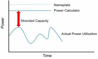
• Faceplate power allocation: The server faceplate power rating is the maximum rated power for a given system. For example, the Cisco UCS 5108 chassis has up to four 2500W output power supplies, and AC input power is 2790 volt-amperes (VA) at 200 VAC. Full power specifications can be found in the Cisco UCS Site Preparation Guide and Installation Guides for the Cisco UCS C-Series, at http://www.cisco.com/en/US/products/ps10477/products_documentation_roadmaps_list.html.
All four supplies are required to achieve 2N redundancy. In other words, the system is provisioned with double the necessary capacity to be able to tolerate the loss of a utility feed. The faceplate power consumption for the Cisco UCS 5108 chassis is therefore 5580VA. Based on faceplate power, you would be able to put only a single Cisco UCS chassis on a Type 1 Cisco PDU. However, it is highly unlikely that the actual power for a Cisco UCS 5108 chassis will ever reach the 5580 VA faceplate number.
• Allocation based on Cisco power calculator: The IT industry has recognized that data center provisioning based on the faceplate is too conservative. Users rarely configure servers so that they are equipped with the maximum CPU quantity and performance, memory, disks, I/O, etc. Power calculators can help by allowing users to enter their configuration to provide a closer estimate of power consumption. You can find the Cisco UCS power calculator at http://www.cisco.com/assets/cdc_content_elements/flash/dataCenter/cisco_ucs_power_calculator/.
Although power calculators provide an improved means for estimating power, they are still somewhat conservative. Even for a given system configuration, the power will vary widely based on the application and use. For the Cisco UCS power calculator, the 100 percent power value represents the highest power consumption that can be achieved on the system. The application used to measure that value uses intense floating-point math and is extremely CPU and memory intensive. Therefore, the 100 percent power value likely is the power value that might be achieved with an HPC application. Enterprise Cisco UCS deployments realistically will not approach the 100 percent maximum power value, even if CPU use reaches 100 percent. For example, a database that increases CPU utilization to 100 percent will likely approach only the 50 percent utilization power value indicated by the power calculator. Therefore, to estimate the power for a typical enterprise Cisco UCS deployment using the power calculator, Cisco suggests using 50 percent utilization.
• Direct power measurement: In estimating power, you cannot get more accurate than direct measurement. Direct measurement will almost certainly yield a lower power value than that determined through the power calculator (even at 50 percent) or faceplate. However, provisioning circuit capacity on the basis of this value results in a high risk of nuisance breaker trips. Workloads in the data center evolve over time. What represents the maximum realistic power today may be well below the maximum power achievable when new software or workloads are introduced. Sophisticated end users that accept the risk of this approach carefully control their workloads and usually factor in an appropriate safety margin.
• Cisco group power capping: Cisco group power capping is an excellent way to achieve the economic benefits of lean power provisioning while maintaining an operational safety net (Figure 9). Power capping allows the end user to specify the maximum aggregate power for a group of Cisco UCS systems managed by any Cisco UCS Manager instance. For data center provisioning, the logical way to use capping is to organize all the servers that draw power from one circuit into a single group. A power cap can then be set for the group that protects the data center from tripping circuit breakers. Successfully using power capping involves three steps:
– Measure actual power while running the target application on the desired server configuration
– Plan your data center deployment so that the servers are grouped onto circuits so that the actual maximum power does not exceed the circuit capacity
– Create a power group and set the cap so that it matches the circuit capacity
Figure 9. Power Capping
Power capping can offer significant benefits, but it can also be misused. If the power cap is set below the actual maximum power, server performance will be affected. In general, performance reduction is the mechanism used to cap power. For more information on Cisco Group Power Capping see the Power Management in the Cisco Unified Computing System: An Integrated Approach White Paper at http://www.cisco.com/en/US/solutions/collateral/ns340/ns517/ns224/ns944/white_paper_c11-627731.html.
Step 2: Gather the Facility Power and Cooling Parameters
Before the rack and PDU solution can be designed, you must understand the capabilities of the data center facility as well as the requirements of the equipment. The facility must provide space, power, and cooling:
• Space: Physical space in the rack is quantified in rack units (RU), which are units of vertical space. 1RU of space is 1.75 inches high in the rack; 42RUs is the amount of vertical space available in the Cisco R42610 Rack. Space is typically the least limiting factor in IT equipment deployment density. Often, the amount of equipment that can be deployed in the rack is limited by the capability to deliver power or remove heat.
• Power: To quantify the power delivery capability of an AC power circuit in the data center, you must know its voltage and maximum usable current. Often the usable current is less than the maximum rated current. For example, in the United States, all power circuits must be de-rated by 20 percent to meet the national electrical code: that is, in the United States, a 20-ampere (A) circuit can carry only a sustained load of up to 16A.
For a single-phase power circuit:
– Maximum power = Voltage x Usable current
For a three-phase power circuit:
– Maximum power = Phase-to-phase voltage x Usable current x 1.73
The higher power capacity of three-phase circuits enables fewer power circuits for a fixed load. Many PDU vendors offer PDUs that accept three-phase power input and provide single-phase power to the equipment power sockets. Note that, in many data centers, the capability to remove heat tends to be a bigger constraint than the capability to deliver power. For data centers without adequate cooling, increased power delivery capability does nothing to improve achievable power density.
• Cooling: All power that is delivered to IT equipment is converted to heat. In many data centers, the capability to cool the servers is the limiting factor in rack deployment density. Factors such as the use of hot-aisle and cold-aisle designs, the use of blanking panels, and the layout of floor tiles affect the actual amount of equipment that can be cooled per rack. Most facilities are built with a cooling limit in mind. However, since operating practices effect achievable capacity, true cooling capacity may drift over time in any given facility. The only way to make any assumptions about the cooling capacity of a given data center is to ask someone familiar with the limitations of that facility.
Step 3: Design the PDU Solution
The final step in the power solution design process is matching the facility capabilities to the IT equipment power requirements. These two parameters were defined in Steps 1 and 2.
The design step is best explained through specific examples, provided in the appendix at the end of this document.
Cisco PDUs
Cisco currently offers two types of branded PDUs:
• Blade-optimized PDU
• Rack-optimized PDU
Within these types, the PDU offerings are divided between units designed for U.S.-type facility plugs, and units designed for international-type plugs. After you have identified the desired type of PDU and facility plug, you have enough information to determine the Cisco part number.
At a high level, the current Cisco PDU offerings are intended to match the requirements of most deployments. For example, Cisco PDUs are currently all designed to consume single-phase input power from the facility. If you have special needs, such as three-phase input power or monitored PDU solutions, you can find a solution from many other providers.
Cisco Blade-Optimized PDU (Type 1)
The Cisco blade-optimized PDU has four IEC C19 receptacles and two C13 receptacles. The PDU receptacle configuration is optimized for use with larger equipment such as the Cisco UCS 5108 chassis. The C19 receptacles can be used to power larger systems, such as the Cisco UCS 5108 chassis, and the C13 receptacles have been added to power smaller rack-level equipment, such as the Cisco UCS 6100 Series Fabric Interconnects.
The Type 1 receptacle configuration is shown in Figure 10.
Figure 10. Type 1 Receptacle Configuration
Although all Type 1 PDUs are configured with the same equipment power sockets, they can be selected with different facility-level plugs. The PDU designed mainly for U.S. customers uses the L6-30 power receptacle. The International PDU is designed with an IEC 309 power plug. Table 6 summarizes the Type 1 specifications for the two models.
Table 6. Type 1 Power Socket Models
U.S.-Optimized Model
International Model
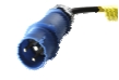
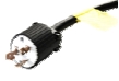
Facility plug type
L6-30P
IEC309-29-3w-32
Facility plug image
Nominal voltage
208V
230V
Equipment sockets
4 C19 and 2 C13
4 C19 and 2 C13
Maximum usable current
24A
32A
Maximum total power
4990W
7360W
PDU dimensions (height x depth x width)
1.75 x 13.8 x 17.6 in. (45 x 350 x 447 mm
1.75 x 13.8 x 17.6 in. (45 x 350 x 447 mm
Weight
11.1 lb (5 kg)
11.1 lb (5 kg)
Mounting options
1RU or 0RU
1RU or 0RU
Part number
RP208-30-1P-U-1
RP230-32-1P-U-1
The maximum total power for the international version is higher because the input connector is built for a higher voltage and current.
Type 1 PDUs can be mounted in either a 0RU or 1RU configuration.
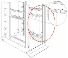
One advantage of the 0RU, side-pocket mounted configuration, shown in Figure 11, is that it does not take up rack space otherwise usable by servers. In the context of Cisco UCS, for example, 0RU mounting allows installation of six Cisco UCS 5108 chassis and one pair of redundant Cisco UCS 6120XP fabric interconnects.
Figure 11. Type 1 0RU Mounting Configuration
The Cisco Type 1 PDU can be mounted in a 1RU configuration by mounting the PDU horizontally in the space normally occupied by the server hardware, shown in Figure 12. This mounting option consumes some of the vertical height otherwise usable by server hardware; however, rack density is rarely limited by physical space. Normally, the capability to power or cool the IT equipment in the rack is a constraint limiting the number of physical servers that can be housed in the rack. 1RU mounting provides easy access to the PDU plugs and breakers.
Figure 12. Type 1 1RU Mounting Configuration
Cisco Rack-Optimized PDU (Type 2)
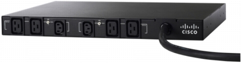
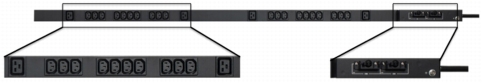
The Cisco UCS rack-optimized PDU has four IEC C19 receptacles and 20 C13 receptacles. The PDU receptacle configuration is optimized for rack configurations that use mostly rack-mount servers, which typically use C13-terminated power cords.
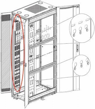
The Type 2 receptacle configuration is shown in Figure 13.
Figure 13. Type 2 Receptacle Configuration
Note that the bottom section of Figure 13 simply shows an expanded view of the equipment power receptacles on one section of the PDU.
Table 7 summarizes the Type 2 specifications for the two models.
Table 7. Type 2 Power Socket Models
U.S.-Optimized Model
International Model
Facility plug type
L6-30P
IEC309-29-3w-32
Facility plug image
Nominal voltage
208V
230V
Equipment sockets
4 C19 and 20 C13
4 C19 and 20 C13
Maximum usable current
24A
32A
Maximum total power
4990W
7360W
PDU dimensions (height x depth x width)
60.6 x 17.4 x 3.4 in.
(1540 x 44 x 85 mm)
17.6 x 13.8 x 18 x 11.1 in
(447 x 350 x 45 x 5 mm)
Mounting options
0RU
0RU
Part number
RP208-30-1P-U-2
RP230-32-1P-U-2
Like the Type 1 PDU, the international Type 2 PDU supports a greater total load because of the higher facility receptacle voltage and current rating.
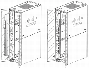
Because of the length of the Type 2 PDU, only 0RU mounting is supported, as shown in Figure 14. Type 2 PDUs can be installed in the back of the rack. Up to six Type 2 PDUs will fit in the 0RU space at the back of the Cisco R42610 Rack.
Figure 14. Type 2 0RU Mounting Configuration
The traditional 0RU mounting configuration, with the plugs facing sideways, may not work if the equipment installed in the rack is too deep. An alternative rear-facing configuration, useful for deep equipment, is shown in Figure 15. Only two PDUs can be installed per rack if the rear-facing configuration is used.
Figure 15. Rear-Facing Type 2 Mounting Configuration
One excellent resource for information and best practices is the Green Grid (http://www.thregreengrid.org). The Green Grid is comprised of both equipment manufacturers, datacenter design firms and end-users and has a wealth of in-depth information regarding IT Energy Efficiency standards and practices.
Also, ASHRAE (American Society of Heating, Refrigeration and Air-Conditioning) has provided excellent datacenter facility guidelines through Technical Committee 9.9 (TC 9.9).
Example 1: Medium-Density Blade Deployment (Four Chassis)
Table 8 summarizes the configuration for Example 1.
Table 8. Example 1 Rack-Level Equipment Configuration
Quantity
Type
Blade Type
Blade Configuration
4
Cisco UCS 5108 chassis
8 Cisco UCS B200 M2 servers
2 Intel Xeon X5670 processors and 12 8-GB low-voltage DIMMs
0 local disks and 1 Cisco virtual interface card (VIC)
2
Cisco UCS 6120XP fabric interconnects
-
-
Step 1: Gather the IT Equipment Power Requirements
Requirement 1: Power Redundancy
The customer requires full 2N redundancy.
Requirement 2: Number of Required Power Receptacles
Calculate the number of power receptacles needed:
Equipment Type
Power Receptacles for Each (per AC Feed)
Quantity
Total Receptacles for Type (per AC Feed)
Cisco UCS 5108 chassis
2 C19 + 0 C13
4
8 C19 + 0 C13
Cisco UCS 6120XP fabric interconnect
0 C19 + 1 C13
2
0 C19 + 2 C13
Total plugs (per AC feed)
8 C19 + 2 C13
These requirements are for each AC feed. Since the customer has specified a grid redundant configuration, there will be two AC inputs. In general, the number of plugs required depends on the desired redundancy. For the Cisco UCS 5108 chassis with grid redundancy, two power supplies are wired to each AC input. If N+1 redundancy had been selected, three plugs would have been required, and they would have all been connected to one AC source.
Requirement 3: Power Capacity
Power is based on 50 percent utilization in the Cisco power calculator:
Type
Power per Unit
Number of Units
Total Power
Cisco UCS 5108 chassis
2133W
4
8352W
Cisco UCS 6120XP fabric interconnect
321W
2
642 W
Rack Total
8994W
Each independent AC input must be sized to support this entire load. With grid redundancy, the system may operate at half this load when both AC sources are available. However, if an AC source is lost, the load will shift, and the remaining source must have enough capacity to carry the load.
Step 2: Gather the Facility Power and Cooling Parameters
Table 9 lists facilities information for Example 1.
Table 9. Example 1 Facilities Information
Facility plug type
L6-30 (24A)
Voltage
208V
Power per plug
24A x 208V = 4990W
This example uses a typical single-phase facility receptacle for the United States. Since the rack-level power consumption is estimated at 8994W and each plug can deliver only a sustained 4990W, you will need at least two plugs per AC power source. The customer has specified that power is grid redundant, so you will need a total of four plugs (two from each independent AC power source).
Calculate the amount of rack space used:
Item
Rack Height
Rack Space Consumed
Cisco R42610 Rack
1
+42RU
Cisco UCS 5108 chassis
4 x 6RU = 24RU
-24RU
Cisco UCS 6120XP fabric interconnect
2 x 1RU = 2RU
-2RU
Remaining space
16RU
Note that 16RU of physical space remain for PDUs and other equipment. Space that is not consumed should be populated with filler panels.
Step 3: Design the PDU Solution
Determine how many PDUs are required.
Match Capacity to Load
Each AC input must be sized to carry the full power load. Each L6-30 can provide 4990W of continuous power. The total load of the equipment in the rack is 8994W. Two L6-30 circuits can provide 9980W, which is more than enough power.
Determine Whether You Have Enough Power Receptacles
There is 1:1 mapping between the number of facility plugs and the number of PDUs. You need at least two L6-30 plugs per AC power source to handle the power load. Do two PDUs provide enough power receptacles for the equipment in the rack?
Since this is a blade deployment, you need to use the type 0 PDU (because it is the only one with C19 power receptacles.) Each PDU has four C19 and two C13 power plugs. Two PDUs would provide a total of eight C19 and four C13 plugs. From Requirement 2 in Step 1, you can see that this design provides enough receptacles.
Final Configuration
The final design for the system requires four PDUs (two per AC input). Likewise, the data center must have four L6-30 plugs per rack (two from each AC power source). From Step 2, you can see that 16RUs of rack space exist. At least 4RUs of rack space must be available to mount all four PDUs in the 1RU configuration. Therefore, you can mount the PDUs in either the 1RU or 0RU configuration.
Example 2: Large Rack-Mount Deployment (Four Chassis)
Table 10 summarizes the configuration for Example 2.
Table 10. Example Rack-Level Equipment Configuration
Quantity
Type
Blade Configuration
10
Cisco UCS C210 M2
2 Intel Xeon X5670 processors and 12 8-GB low-voltage DIMMs
4 73-GB 15,000-rpm SAS drives
1
Cisco Nexus 2248TP GE Fabric Extender
-
Step 1: Gather the IT Equipment Power Requirements
Requirement 1: Power Redundancy
The customer requires N+1 redundancy.
Requirement 2: Number of Required Power Receptacles
Calculate the number of power receptacles needed:
Equipment Type
Power Receptacles for Each (per AC Feed)
Quantity
Total Receptacles for Type (per AC Feed)
Cisco UCS C210 M1 or M2 server
0 C19 + 2 C13
10
0 C19 + 20 C13
Cisco Nexus 2248TP GE Fabric Extender
0 C19 + 1 C13
1
0 C19 + 2 C13
Total plugs (per AC feed)
0 C19 + 22 C13
Since the facility has been designed for N+1 redundancy (rather than grid), there is only one AC power source. Therefore, the requirements (per AC feed) are the same as the total power requirements.
Requirement 3: Power Capacity
Cisco UCS C210 power was estimated using 50 percent utilization in the power calculator; Cisco Nexus 2248TP power was estimated using the typical power from the data sheet:
Type
Power per Unit
Number of Units
Total Power
C210 M2 server
340 W
10
3400 W
Nexus 2248TP
110W
1
110 W
Rack Total
3510W
Step 2: Gather the Facility Power and Cooling Parameters
Table 11 lists facilities information for Example 2.
Table 11. Example 2 Facilities Information
Facility plug type
L6-30 (24A)
Voltage
208V
Power per plug
24A x 208V = 4990W
This example uses a typical single-phase facility receptacle for the Unified States. In this example, a single facility power plug provides more than enough power capacity for everything in the rack. However, as you will see later, the equipment in the rack needs more than one PDU to provide enough receptacles.
Calculate the amount of rack space used:
Item
Rack Height
Rack Space Consumed
Cisco R42610 Rack
1
+42RU
Cisco UCS C210
20 x 2RU = 20RU
-20RU
Cisco Nexus 2248TP
1 x 1RU = 1RU
-1RU
Remaining space
21RU
Note that 21RU of physical rack space remain after all the equipment is installed.
Step 3: Design the PDU Solution
Determine how many PDUs are required.
Match Capacity to Load
Each AC input must be sized to carry the full power load. Each L6-30 plug can provide 4990W of continuous power. The total load of the equipment in the rack is only 3600W. One facility plug can, in theory, provide enough power for everything in the rack
Determine Whether You Have Enough Power Receptacles
Since there is enough power with a single facility plug, you may be able to get by with only a single PDU. However, you need to make sure that a single PDU provides enough power receptacles.
Since this is a rack configuration with lots of C13 receptacles, the Cisco Type 2 plug is the best choice. The type 2 PDU has 4 C19 and 20 C13 receptacles. Since the rack mount servers need 22 C13 sockets, the PDU technically does not have enough.
There are two choices:
• Use two PDUs and put five servers on each PDU
• Use one PDU and use two of the C19 plugs
For the second option, you would need to use a nonstandard cable with C19-to-C14 plugs. This type of cable is acceptable because a C19 receptacle can provide more power than a C13 receptacle. However, you should not use a cable that connects a power supply with a C20 to a C13 power receptacle.
Final Configuration
The final design for this configuration depends on whether you use C19 plugs for the servers. If you do, only one L6-30 socket and PDU are required. However, if the solution is to be designed using only the Cisco standard C13-to-C14 cable, two PDUs and facility plugs are required.