Oracle Reference Architecture with VMware vSphere 5.1 and Cisco Nexus 1000V
July 2013
Executive Summary
Introduction
Industry trends indicate a vast data center transformation toward shared infrastructures. Enterprise customers are moving away from silos of information and moving toward shared infrastructures to virtualized environments and eventually to the cloud to increase agility and operational efficiency, optimize resource utilization, and reduce costs.
This white paper describes how the Cisco Unified Computing System™ (Cisco UCS®) can be used in conjunction with NetApp fabric-attached storage (FAS) systems to implement the Oracle Real Application Clusters (RAC) solution in a virtualized environment.
FlexPod is a pretested data center solution built on a flexible, scalable, shared infrastructure consisting of Cisco UCS servers with Cisco Nexus® switches and NetApp unified storage systems running Data ONTAP. The FlexPod components are integrated and standardized to help you eliminate the guesswork and achieve timely, repeatable, consistent deployments. FlexPod has been optimized with a variety of mixed application workloads and design configurations in various environments such as virtual desktop infrastructure and secure multitenancy environments.
Customers should accelerate their transition to the cloud with the FlexPod data center solution, which integrates the disparate computing, storage, and network components into a single architecture that scales to fit a variety of virtualized and nonvirtualized customer environments. With the increased complexity and extreme performance requirements, FlexPod with Cisco UCS can reduce business risk and increase data center efficiency, protecting current investments while scaling for future growth.
The key benefits of FlexPod deployment are as follows:
• Single platform from industry leaders in networking, computing, and storage
• Pretested, validated solution to reduce risk and increase efficiency
• Flexible IT architecture for today's needs, yet scales for future growth
• Cooperative support model for efficient and streamlined resolution
FlexPod for VMware includes NetApp storage, Cisco® networking, Cisco UCS, and VMware virtualization software in a single package. This solution is deployed and tested on a defined set of hardware and software.
This document is intended to assist solution architects, project managers, infrastructure managers, sales engineers, field engineers, and consultants in planning, designing, and deploying Oracle Database 11g Release 2 (R2) RAC hosted on VMware virtualization solutions in a FlexPod environment. It assumes that the reader has an architectural understanding of Cisco UCS, Cisco networking, VMware, Oracle Database 11g R2 Grid Infrastructure, Oracle RAC database, NetApp storage system, and related software.
Purpose of This Guide
This white paper demonstrates how enterprises can apply best practices to deploy Oracle Database 11g R2 RAC using VMware vSphere, VMware vCenter, Cisco UCS, Cisco Nexus switches, and NetApp FAS storage. This design solution presents the scaling and consolidation study of multiple two-node Oracle Database 11g R2 RACs in a virtualized environment using a typical online transaction processing (OLTP) workload.
Business Needs
Business applications are moving into the consolidated computing, network, and storage environment. Implementing the FlexPod for VMware architecture helps to reduce the costs and complexity of every component of a traditional Oracle Database 11g R2 RAC deployment. The complexity of integration management is also reduced while maintaining the multiple Oracle Database 11g R2 RACs.
The following are the business needs for deploying Oracle Database 11g R2 RAC in a virtualized environment:
• Consolidate multiple Oracle Database 11g R2 RACs on the same physical server.
• Increase the database administrator's productivity by using NetApp products such as Snapshot and FlexClone.
• Reduce Oracle licensing costs by consolidating multiple Oracle Database 11g R2 RACs on the same physical server.
• Save costs, power, and lab space by reducing the number of physical servers.
• Enable a global virtualization policy and eliminate the need to manage bare-metal servers to run Oracle databases.
• Take advantage of using the Cisco Nexus 1000V Switch, which is well integrated with VMware vSphere.
• Take advantage of vSphere management policies.
• Create a balanced configuration that yields predictable purchasing guidelines at the computing, network, and storage tiers for a given workload.
Solution Overview
Oracle Database 11g R2 RAC on FlexPod with VMware and Cisco Nexus 1000V
This solution provides an end-to-end architecture with Cisco UCS, VMware, Oracle, and NetApp technologies that demonstrate the implementation of Oracle Database 11g R2 RAC on FlexPod and VMware with the Cisco Nexus 1000V and highlight the advantages of using Cisco UCS Virtual Interface Cards (VICs) and the Oracle Direct NFS client. This solution also demonstrates the scalability and consolidation of multiple Oracle Database 11g R2 RACs on FlexPod for VMware and the Oracle Direct NFS client.
The following are the key features of this solution:
• Each virtual machine (VM) has a dedicated virtual interface port.
• Each VMware ESXi boots up using iSCSI target.
• VM traffic is directed to the dedicated interface on the Cisco Nexus 1000V Switch.
• The VMware ESXi 5.x is used as the hypervisor for deploying VMs.
• The software-based Cisco Nexus 1000V Switch is used in the hypervisor.
The following components are used for the design and deployment:
• Oracle Database 11g R2 RAC
• Cisco UCS 2.1 (1a) server platform
• Cisco Nexus 5548UP Switches
• Cisco Nexus 1000V Switch
• VMware vSphere 5.1 virtualization platform
• Data center business advantage architecture
• LAN architectures
• NetApp storage components
• NetApp OnCommand System Manager 2.1
• Swingbench benchmark kit for OLTP workloads
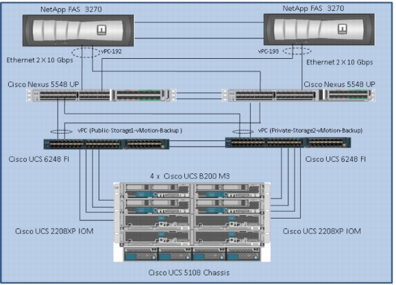
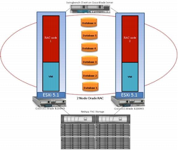
Figure 1 shows the solution architecture of the design solution discussed in this white paper.
Figure 1. Solution Architecture
Technology Overview
Cisco Unified Computing System
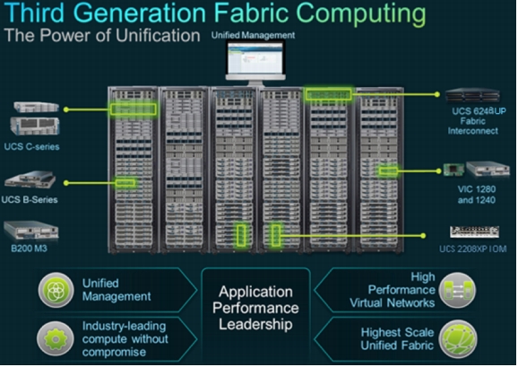
The Cisco Unified Computing System (Cisco UCS) is a third-generation data center platform that unites computing, networking, storage access, and virtualization resources into a cohesive system designed to reduce total cost of ownership (TCO) and increase business agility. The system integrates a low-latency, lossless 10 Gigabit Ethernet unified network fabric with enterprise-class x86-architecture servers. The system is an integrated, scalable, multichassis platform in which all resources participate in a unified management domain that is controlled and managed centrally. Figure 2 shows the unification of the computing, network, and storage in a Cisco UCS environment.
Figure 2. Cisco Unified Computing Components in a Data Center
The following are the main components of the Cisco UCS:
• Computing: The system is based on an entirely new class of computing system that incorporates blade servers based on Intel® Xeon® E5-2600 Series processors. The Cisco UCS blade servers offer the patented Cisco Extended Memory technology to support applications with large datasets and allow more virtual machines per server.
• Network: The system is integrated into a low-latency, lossless, 80-Gbps unified network fabric. This network foundation consolidates LANs, SANs, and high-performance computing networks that are separate networks today. The unified fabric lowers costs by reducing the number of network adapters, switches, and cables, and by decreasing the power and cooling requirements.
• Virtualization: The system unleashes the full potential of virtualization by enhancing the scalability, performance, and operational control of virtual environments. Cisco security, policy enforcement, and diagnostic features are now extended into virtualized environments to better support changing business and IT requirements.
• Storage access: The system provides consolidated access to both SAN storage and network attached storage (NAS) over the unified fabric. By unifying the storage access, Cisco UCS can access storage over Ethernet, Fibre Channel (FC), Fibre Channel over Ethernet (FCoE), and iSCSI. This provides customers with choices for storage access and investment protection. In addition, the server administrators can preassign storage-access policies for system connectivity to storage resources, simplifying storage connectivity and management for increased productivity.
• Management: The system uniquely integrates all system components, enabling the entire solution to be managed as a single entity by Cisco UCS Manager. Cisco UCS Manager has an intuitive graphical user interface (GUI), a command-line interface (CLI), and a robust application programming interface (API) to manage all system configuration and operations.
Cisco UCS is designed to deliver the following benefits:
• Reduced TCO, increased ROI, and increased business agility.
• Increased IT staff productivity through just-in-time provisioning and mobility support.
• A cohesive, integrated system that unifies the technology in the data center. The system is managed, serviced, and tested as a whole.
• Scalability through a design for hundreds of discrete servers and thousands of virtual machines and the capability to scale I/O bandwidth to match demand.
• Industry standards supported by a partner ecosystem of industry leaders.
Cisco Unified Computing System Components
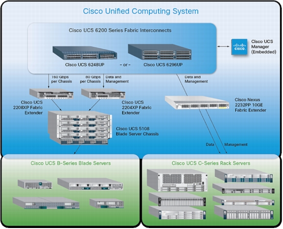
This section describes the various components that constitute Cisco UCS. Figure 3 shows these components.
Figure 3. Cisco UCS Components
Cisco UCS Blade Server Chassis
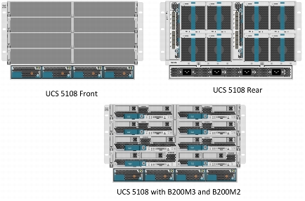
The Cisco UCS 5100 Series Blade Server Chassis is a crucial building block of the Cisco Unified Computing System, delivering a scalable and flexible blade server chassis.
The Cisco UCS 5108 Blade Server Chassis is six rack units (6RU) high and can mount in an industry-standard 19-inch rack. A single chassis can house up to eight half-width Cisco UCS B-Series Blade Servers and can accommodate both half-width and full-width blade form factors.
Four single-phase, hot-swappable power supplies are accessible from the front of the chassis. These power supplies are 92 percent efficient and can be configured to support nonredundant, N+1 redundant, and grid-redundant configurations. The rear of the chassis contains eight hot-swappable fans, four power connectors (one per power supply), and two I/O bays for Cisco UCS 2208XP fabric extenders.
A passive midplane provides up to 40 Gbps of I/O bandwidth per server slot and up to 80 Gbps of I/O bandwidth for two slots. The chassis is capable of supporting future 80 Gigabit Ethernet standards. Figure 4 shows the front, rear, and blade populated views of the Cisco UCS blade server chassis.
Figure 4. Cisco UCS Blade Server Chassis
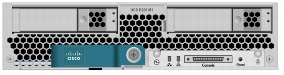
Cisco UCS B200 M3 Blade Server
The Cisco UCS B200 M3 Blade Server is a half-width, two-socket blade server. The system uses two Intel Xeon E5-2600 Series Processors, up to 384 GB of DDR3 memory, two optional hot-swappable small form factor (SFF) serial attached SCSI (SAS) disk drives, and two VIC adapters that provide up to 80 Gbps of I/O throughput. The server balances simplicity, performance, and density for production-level virtualization and other mainstream data center workloads. Figure 5 shows the blade server hardware used in this design solution.
Figure 5. Cisco UCS B200 M3 Blade Server
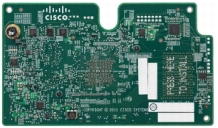
Cisco UCS Virtual Interface Card 1240
A Cisco innovation, the Cisco UCS VIC 1240 is a 4-port 10 Gigabit Ethernet, FCoE-capable modular LAN on motherboard (mLOM) designed exclusively for the M3 generation of Cisco UCS B-Series Blade Servers. When used in combination with an optional port expander, the Cisco UCS VIC 1240 capabilities can be expanded to eight ports of 10 Gigabit Ethernet. Figure 6 shows the Cisco UCS VIC 1240.
Figure 6. Cisco UCS VIC 1240
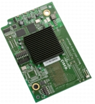
Cisco UCS Virtual Interface Card 1280
A Cisco innovation, the Cisco UCS VIC 1280 is an 8-port 10 Gigabit Ethernet, FCoE-capable mezzanine card designed exclusively for Cisco UCS B-Series Blade Servers. Figure 7 shows the Cisco UCS VIC 1280.
Figure 7. Cisco UCS VIC 1280
The Cisco UCS VIC 1240 and 1280 enable a policy-based, stateless, agile server infrastructure that can present up to 256 PCI Express (PCIe) standards-compliant interfaces to the host that can be dynamically configured as either network interface cards (NICs) or host bus adapters (HBAs). In addition, the Cisco UCS VIC 1280 supports Cisco Nexus 1000V technology, which extends the Cisco UCS fabric interconnect ports to virtual machines, simplifying the server virtualization deployment.
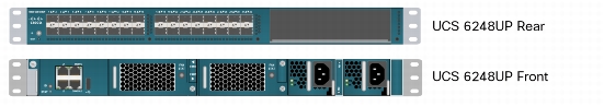
Cisco UCS 6248UP 48-Port Fabric Interconnects
The Cisco UCS 6248UP 48-Port Fabric Interconnects are devices that provide a single point for connectivity and management for the entire system. Typically deployed as an active-active pair, the system's fabric interconnects integrate all components into a single, highly available management domain controlled by Cisco UCS Manager. The fabric interconnects manage all I/O efficiently and securely at a single point, resulting in deterministic I/O latency regardless of a server or virtual machine's topological location in the system.
The Cisco UCS 6200 Series Fabric Interconnects support the system's 80-Gbps unified fabric with low-latency, lossless, cut-through switching that supports IP, storage, and management traffic using a single set of cables. The fabric interconnects feature virtual interfaces that terminate both physical and virtual connections equivalently, establishing a virtualization-aware environment in which blade servers, rack servers, and virtual machines are interconnected using the same mechanisms. The Cisco UCS 6248UP is a 1RU fabric interconnect that features up to 48 universal ports that can support 80 Gigabit Ethernet, FCoE, or native FC connectivity. Figure 8 shows the Cisco UCS fabric interconnect hardware used in this design solution.
Figure 8. Cisco UCS 6248UP Fabric Interconnect
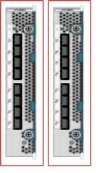
Cisco UCS 2200 Series Fabric Extenders
The Cisco UCS fabric extenders are zero-management, low-cost, low-power-consuming devices that distribute the system's connectivity and management planes into rack and blade chassis to scale the system without complexity. Designed never to lose a packet, Cisco fabric extenders eliminate the need for top-of-rack switches and blade-server-resident Ethernet and FC switches and management modules, dramatically reducing the infrastructure cost per server. Figure 9 shows the Cisco fabric extender hardware.
Figure 9. Cisco UCS 2208XP Fabric Extenders
The Cisco UCS 2208XP fabric extenders bring the unified fabric and management planes into the Cisco UCS 5108 Blade Server Chassis. Typically deployed in pairs, each device brings up to 80 Gbps of bandwidth to the blade server chassis, for a total of up to 160 Gbps across up to eight servers. Each half-width blade has access to up to 80 Gbps of bandwidth.
Cisco UCS Manager
Cisco UCS Manager is an embedded, unified manager that provides a single point of management for Cisco UCS. It can be accessed through an intuitive GUI, a CLI, or the comprehensive open XML API. Cisco UCS Manager manages the physical assets of the server and storage and LAN connectivity and is designed to simplify the management of virtual network connections through integration with several major hypervisor vendors. It provides IT departments with the flexibility to allow people to manage the system as a whole, or to assign specific management functions to individuals based on their roles as managers of server, storage, or network hardware assets. It simplifies operations by automatically discovering all the components available on the system and enabling a stateless model for resource use.
The elements managed by Cisco UCS Manager include:
• BIOS firmware and settings, including server universal user ID (UUID) and boot order
• Converged network adapter (CNA) firmware and settings, including MAC addresses and worldwide names (WWNs) and SAN boot settings
• Virtual port groups used by the virtual machines, using the Cisco Nexus 1000V Switches
• Interconnect configuration, including uplink and downlink definitions, MAC address pinning, VLANs, quality of service (QoS), bandwidth allocations, and EtherChannel to upstream LAN switches
Cisco UCS is designed to be programmable and self-integrating. A server's entire hardware stack, ranging from the server firmware and settings to network profiles, is configured through model-based management. With Cisco VICs, even the number and type of I/O interfaces is programmed dynamically, making every server ready to power any workload at any time.
With model-based management, administrators manipulate a model of a desired system configuration and associate the model's service profile with hardware resources, and the system configures itself to match the model. This automation accelerates provisioning and workload migration with accurate and rapid scalability. The result is increased IT staff productivity, improved compliance, and reduced risk of failures due to inconsistent configurations.
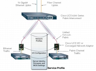
Cisco UCS Service Profiles
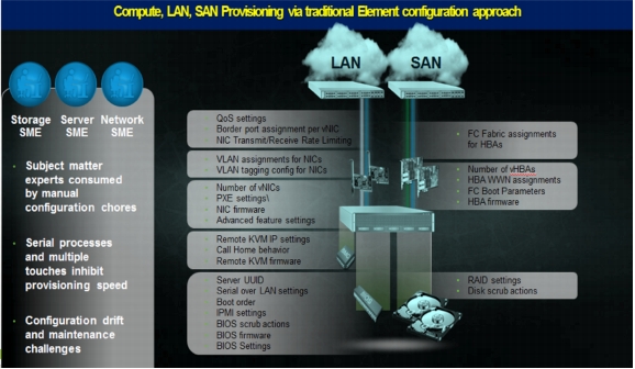
Traditional Provisioning Approach
A server's identity is made up of numerous properties, such as UUID, boot order, Intelligent Platform Management Interface (IPMI) settings, BIOS firmware, BIOS settings, RAID settings, disk scrub settings, number of NICs, NIC speed, NIC firmware, MAC and IP addresses, number of HBAs, HBA WWNs, HBA firmware, FC fabric assignments, QoS settings, VLAN assignments, and remote keyboard/video/monitor. The extensive list of properties means multiple points of configuration that give a server its identity and make it unique within the data center. Some of these parameters are linked to the hardware of the server itself (such as the BIOS firmware version, BIOS settings, boot order, FC boot settings, etc.), while some settings are linked to the network and storage switches (such as VLAN assignments, FC fabric assignments, QoS settings, and access control lists [ACLs]). Figure 10 shows the traditional provisioning approach employed in the data center.
Figure 10. Traditional Provisioning Approach in the Data Center
The complexity and immensity of the properties pose the following challenges in the server deployment:
• Lengthy deployment cycles
– Every deployment requires coordination among server, storage, and network teams
– Need to ensure correct firmware and settings for hardware components
– Need appropriate LAN and SAN connectivity
• Response time to business needs
– Tedious deployment process
– Manual, error-prone processes that are difficult to automate
– High operating expenses (OpEx)
– Outages caused by human errors
• Limited OS and application mobility
– Storage and network settings tied to physical ports and adapter identities
– Static infrastructure leads to overprovisioning, higher OpEx
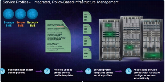
Cisco UCS has uniquely addressed these challenges with the introduction of service profiles that enable integrated, policy-based infrastructure management. Cisco UCS service profiles hold the DNA for nearly all configurable parameters required to set up a physical server. A set of user-defined policies (rules) allow quick, consistent, repeatable, and highly secure deployments of the Cisco UCS servers.
Figure 11 shows the integrated, policy-based infrastructure management made possible due to the service profiles.
Figure 11. Service Profiles in the Cisco UCS
Cisco UCS service profiles contain values for a server's property settings, including virtual network interface cards (vNICs), MAC addresses, boot policies, firmware policies, fabric connectivity, external management, and other high-availability information. Abstracting these settings from the physical server into a Cisco service profile enables the service profile to be deployed to any physical computing hardware within the Cisco UCS domain. Furthermore, service profiles can, at any time, be migrated from one physical server to another. This logical abstraction of the server personality separates the dependency of the hardware type or model and is a result of Cisco's unified fabric model (rather than overlaying software tools on top).
This innovation is still unique in the industry, despite competitors claiming to offer similar capabilities. In most cases, the vendors must rely on several different methods and interfaces to configure these server settings. Furthermore, Cisco is the only hardware provider to offer a truly unified management platform, with Cisco UCS service profiles and hardware abstraction capabilities extending to both blade and rack servers.
Service Profiles and Templates
A service profile contains configuration information about the server hardware, interfaces, fabric connectivity, and server and network identity. Cisco UCS Manager provisions servers using service profiles. It implements role-based and policy-based management focused on service profiles and templates. A service profile can be applied to any blade server to provision it with the characteristics required to support a specific software stack. It allows server and network definitions to move within the management domain, enabling flexibility in the use of system resources.
The service profile templates are stored in the Cisco UCS 6200 Series Fabric Interconnects for reuse by the server, network, and storage administrators. Service profile templates consist of server requirements and the associated LAN and SAN connectivity. These templates allow different classes of resources to be defined and applied to a number of resources, each with its own unique identities assigned from predetermined pools. Cisco UCS Manager can deploy the service profile on any physical server at any time. When a service profile is deployed to a server, Cisco UCS Manager automatically configures the server, adapters, fabric extenders, and fabric interconnects to match the configuration specified in the service profile. A service profile template parameterizes the UUIDs that differentiate between server instances.
This automation of device configuration reduces the number of manual steps required to configure servers, NICs, HBAs, and LAN and SAN switches.
Figure 12 shows a service profile that contains abstracted server state information, creating an environment to store unique information about a server.
Figure 12. Service Profile
Programmatically Deploying Server Resources
Cisco UCS Manager provides centralized management capabilities, creates a unified management domain, and serves as the central nervous system of the Cisco UCS. It is embedded device management software that manages the system from end to end as a single logical entity through an intuitive GUI, CLI, or XML API. Cisco UCS Manager implements role- and policy-based management using service profiles and templates. This construct improves IT productivity and business agility by enabling infrastructure to be provisioned in minutes instead of days, shifting IT's focus from maintenance to strategic initiatives.
Dynamic Provisioning with Service Profiles
Cisco UCS resources are abstract in the sense that their identity, I/O configuration, MAC addresses and WWNs, firmware versions, BIOS boot order, and network attributes (including QoS settings, ACLs, pin groups, and threshold policies) all are programmable using a just-in-time deployment model. Cisco UCS Manager stores this identity, connectivity, and configuration information in service profiles that reside on the Cisco UCS 6200 Series Fabric Interconnect. A service profile can be applied to any blade server to provision it with the characteristics required to support a specific software stack. A service profile allows server and network definitions to move within the management domain, enabling flexibility in the use of system resources. Service profile templates allow different classes of resources to be defined and applied to a number of resources, each with its own unique identities assigned from predetermined pools.
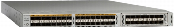
Cisco Nexus 5548UP Switch
The Cisco Nexus 5548UP is a 1RU 1 and 10 Gigabit Ethernet switch offering up to 960 Gbps throughput and scaling up to 48 ports. It offers thirty-two 1 and 10 Gigabit Ethernet fixed Enhanced Small Form-Factor Pluggable (SFP+) Ethernet/FCoE or 1/2/4/8-Gbps native FC unified ports and three expansion slots. These slots have a combination of Ethernet/FCoE and native FC ports. Figure 13 shows the Cisco Nexus 5548UP Switch.
Figure 13. Cisco Nexus 5548UP Switch
Cisco Nexus 1000V
The Cisco Nexus 1000V Switch for VMware vSphere is a virtual machine access switch that is an intelligent software switch implementation based on the IEEE 802.1Q standard for VMware vSphere environments running the Cisco NX-OS operating system. Operating inside the VMware ESX hypervisor, the Cisco Nexus 1000V Switch supports Cisco VN-Link server virtualization technology.
With the Cisco Nexus 1000V, you can have a consistent networking feature set and provisioning process all the way from the virtual machine access layer to the core of the data center network infrastructure. Virtual servers can now use the same network configuration, security policy, diagnostic tools, and operational models as their physical server counterparts attached to dedicated physical network ports. Virtualization administrators can access predefined network policy that follows mobile virtual machines to help ensure proper connectivity, saving valuable time. Developed in close collaboration with VMware, the Cisco Nexus 1000V Switch is certified by VMware to be compatible with VMware vSphere, vCenter, ESX, and ESXi, and with many other vSphere features. You can use the Cisco Nexus 1000V Switch to manage your virtual machine connectivity with confidence in the integrity of the server virtualization infrastructure.
Features and Benefits
The Cisco Nexus 1000V Switch provides a common management model for both physical and virtual network infrastructures through the Cisco VN-Link technology, which includes policy-based virtual machine connectivity, mobility of virtual machine security and network properties, and a nondisruptive operational model.
• Policy-based virtual machine connectivity
To facilitate easy creation and provisioning of virtual machines, the Cisco Nexus 1000V Switch includes port profiles. The port profiles enable you to define VM network policies for different types or classes of VMs and then apply the profiles through VMware vCenter. The port profiles are a scalable mechanism for configuring networks with large numbers of VMs. When the port profiles include QoS and security policies, they formulate a complete service-level agreement (SLA) for the VM's traffic.
• Mobility of virtual machine security and network properties
The network and security policies defined in the port profile follow the virtual machine throughout its lifecycle, whether it is being migrated from one server to another, suspended, hibernated, or restarted. In addition to migrating the policy, the Cisco Nexus 1000V Virtual Supervisor Module (VSM) moves the VM's network state. VMs participating in traffic-monitoring activities can continue these activities uninterrupted by VMware vMotion operations. When a specific port profile is updated, the Cisco Nexus 1000V automatically provides live updates to all the virtual ports using that same port profile. The capability to migrate network and security policies through VMware vMotion makes regulatory compliance much easier to enforce with the Cisco Nexus 1000V because the security policy is defined in the same way as for physical servers and is constantly enforced by the switch.
• Intelligent traffic steering
Besides traditional switching capability, the Cisco Nexus 1000V offers the Cisco vPath architecture to support virtualized network services with intelligent traffic steering. This feature redirects packets in a network flow to a virtual service virtual machine called a Virtual Service Node (VSN), which can be on a different server. Thus, a VSN is not required on every server, providing flexible and consolidated deployment.
• Performance acceleration
The Virtual Ethernet Module (VEM) caches the VSN's decision for a flow, implements the service in all subsequent packets of the flow, and accelerates virtualized network service in the hypervisor kernel.
Enhanced Deployment Scenarios
• Optimized server bandwidth for I/O-intensive applications
Today, network interfaces are often dedicated to a particular type of traffic, such as VMware Console or vMotion. With the Cisco Nexus 1000V, all NICs can be treated as a single logical channel with QoS attached to each type of traffic. Consequently, the bandwidth to the server can be used more efficiently, with network-intensive applications virtualized.
• Easier security audits with consistent security policy
Security audits on virtual machines are usually more difficult to perform because VMs are secured differently than physical servers. Because the Cisco Nexus 1000V provides persistent security policy to mobile VMs, security audits are similar to those for the physical servers.
• Virtual machine as basic building block of data center
With the Cisco Nexus 1000V, virtual machines are treated the same way as physical servers in security policy, monitoring and troubleshooting, and the operational model between network and server administrators, enabling virtual machines to be true basic building blocks of the data center. These operational efficiencies lead to greater scaling of server virtualization deployments with lower operating expenses.
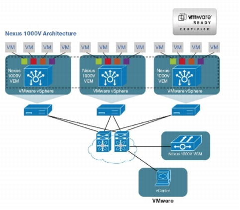
VMware Product Compatibility
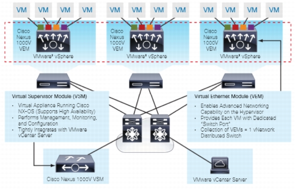
The Cisco Nexus 1000V Switch is compatible with VMware vSphere as a VMware vNetwork distributed switch (vDS) with support for the VMware ESX and the ESXi hypervisors and integration with VMware vCenter Server. The Cisco Nexus 1000V is also compatible with the various VMware vSphere features. Figure 14 illustrates the architecture of the Cisco Nexus 1000V on VMware vSphere.
Product Architecture
The Cisco Nexus 1000V Switch has two major components:
• The Virtual Ethernet Module (VEM), which runs inside the hypervisor
• The external Virtual Supervisor Module (VSM), which manages the VEMs
Figure 14. Cisco Nexus 1000V Architecture
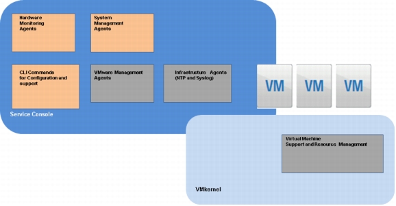
VMware vSphere 5.1 Architecture Overview
The VMware ESXi is an enterprise-level computer virtualization solution. It is a production-proven virtualization layer that runs on physical servers that abstract processor, memory, storage, and networking resources to be provisioned to multiple virtual machines.
In the VMware ESXi architecture (see Figure 15), the VMware Virtualization Kernel (VMkernel) is augmented by a management partition known as the console operating system or service console. The primary purpose of the console operating system is to provide a management interface with the host. Various VMware management agents are deployed in the console operating system, along with other infrastructure service agents (for example, name service, time service, and logging agents). Furthermore, individual administrative users can log in to the console operating system to run the configuration and diagnostic commands and scripts.
Figure 15. VMware ESXi 5.1 Architecture
Virtualization using VMware ESXi provides an abstraction layer that decouples the physical hardware from the operating system to deliver greater IT resource utilization and flexibility. Virtualization allows multiple virtual machines with heterogeneous operating systems (for example, Red Hat Enterprise Linux [RHEL], Microsoft Windows 2008 Server, and SUSE Linux) and applications to run in isolation side by side on the same physical machine. A virtual machine is the representation of a physical machine by software. It has its own set of virtual hardware (RAM, CPU, NICs, hard disks, etc.) on which an operating system and applications are loaded. The operating system sees a consistent, normalized set of hardware regardless of the actual physical hardware components. The VMware VMs contain advanced hardware features such as 64-bit computing and virtual symmetric multiprocessing. Figure 16 shows the server virtualization with VMware ESXi on the Cisco Nexus 1000V Switch.
Figure 16. VMware ESXi 5.1 with Cisco Nexus 1000V
NetApp Storage Technologies and Benefits
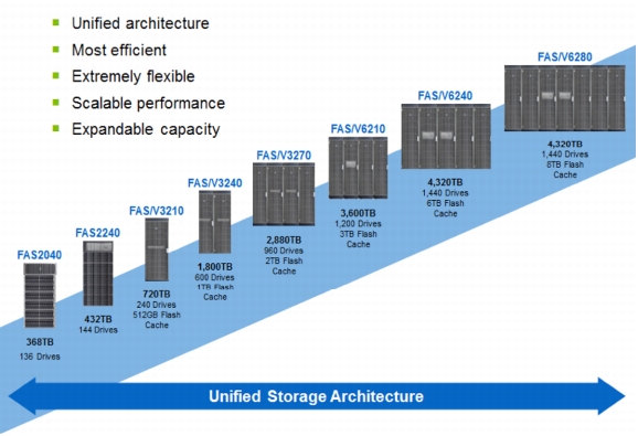
The NetApp storage platform can handle different types of files and data from various sources-including user files, email, and databases. Data ONTAP is the fundamental NetApp software platform that runs on all NetApp storage systems. Data ONTAP is a highly optimized, scalable operating system that supports mixed NAS and SAN environments and a range of protocols, including FC, iSCSI, FCoE, Network File System (NFS), and Common Internet File System (CIFS). The platform includes a patented file system, Write Anywhere File Layout (WAFL), and storage virtualization capabilities. The Data ONTAP platform gives the NetApp unified storage architecture the flexibility to manage, support, and scale to different business environments by using a common knowledge base and tools. This architecture enables users to collect, distribute, and manage data from all locations and applications at the same time. These capabilities allow the investment to scale by standardizing processes, reducing management time, and increasing availability. Figure 17 shows the different NetApp unified storage architecture platforms.
The NetApp storage hardware platform used in this solution is the FAS3270A. The FAS3200 series is an ideal platform for primary and secondary storage for an Oracle Database 11g R2 RAC deployment. An array of NetApp tools and enhancements are available to augment the storage platform. These tools assist in deployment, backup, recovery, replication, management, and data protection. The solution makes use of a subset of these tools and enhancements.
Storage Architecture
The storage design for any solution is a critical element that is typically responsible for a large percentage of the solution's overall cost, performance, and agility.
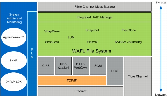
The basic architecture of the storage system's software is shown in Figure 18. A collection of tightly coupled processing modules handles such as CIFS, Fibre Channel over IP (FCP), FCoE, HTTP, iSCSI, and NFS requests. A request starts in the network driver and moves through network protocol layers and the file system, eventually generating disk I/O, if necessary. When the file system finishes the request, it sends a reply back to the network. The administrative layer at the top supports a CLI similar to UNIX that monitors and controls the modules below. In addition to the modules shown, a simple real-time kernel provides basic services such as process creation, memory allocation, message passing, and interrupt handling. The networking layer is derived from the same Berkeley code used by most UNIX systems, with modifications made to communicate efficiently with the storage appliance's file system. The storage appliance provides transport-independent, seamless data access using block- and file-level protocols from the same platform. The storage appliance provides block-level data access over an FC SAN fabric using FCP and over an IP-based Ethernet network using iSCSI. File access protocols such as NFS, CIFS, HTTP, and FTP provide file-level access over an IP-based Ethernet network.
Figure 18. Storage System Architecture
RAID-DP
RAID-DP is NetApp's implementation of double-parity RAID 6, which is an extension of NetApp's original Data ONTAP WAFL RAID 4 design. Unlike other RAID technologies, RAID-DP provides the ability to achieve a higher level of data protection without any performance impact while consuming a minimal amount of storage.
NetApp FlexVol storage-virtualization technology enables you to respond to changing storage needs fast, lower your overhead, avoid capital expenses, and reduce disruption and risk. FlexVol technology aggregates physical storage in virtual storage pools, so you can create and resize virtual volumes as your application needs change.
With FlexVol you can improve-even double-the utilization of your existing storage and save the expense of acquiring more disk space. In addition to increasing storage efficiency, you can improve I/O performance and reduce bottlenecks by distributing volumes across all available disk drives.
NetApp OnCommand System Manager 2.1
NetApp OnCommand System Manager is a powerful management tool for NetApp storage. The System Manager tool helps administrators manage single NetApp storage systems as well as clusters quickly and easily.
Some of the benefits of the System Manager tool are as follows:
• Easy to install
• Easy to manage from a browser
• Does not require storage expertise
• Increases storage productivity and response time
• Cost-effective
• Takes advantage of storage efficiency features such as:
– Thin provisioning
– Compression
– Deduplication
Snapshot
The NetApp Snapshot technology provides zero-cost, near-instantaneous backup, point-in-time copies of the volume or logical unit number (LUN) by preserving the Data ONTAP WAFL consistency points (CPs).
Creating Snapshot copies incurs a minimal effect on performance because data is never moved, as it is with other copy-out technologies. The cost for Snapshot copies is at the rate of block-level changes and not 100 percent for each backup, as it is with mirror copies. Using Snapshot can result in savings in storage cost for backup and restore purposes and opens up a number of efficient data management possibilities.
NetApp's Strategy for Storage Efficiency
NetApp's strategy for storage efficiency is based on the built-in foundation of storage virtualization and unified storage provided by its core Data ONTAP operating system and the WAFL file system. Unlike competitor technologies, the NetApp technologies surrounding its FAS and V-Series product line have storage efficiency built into their core. Customers who already have other vendors' storage systems and disk shelves can still use all the storage-saving features that come with the NetApp FAS system simply by using the NetApp V-Series product line. This is in alignment with NetApp's philosophy of storage efficiency, because customers can continue to use their existing third-party storage infrastructure and disk shelves, yet save more by using NetApp's storage-efficient technologies.
Oracle Database 11g R2 RAC
Oracle Database 11g R2 RAC provides the foundation for IT to successfully deliver more information with a higher quality of service, reduce the risk of change within IT, and make more efficient use of IT budgets. Oracle Database 11g R2 enterprise edition provides industry-leading performance, scalability, security, and reliability on a choice of clustered or single servers with a wide range of options to meet user needs.
Grid computing relieves users from concerns about where data resides and which computer processes their requests. Users request information or computation and have it delivered-as much as they want, whenever they want. For the database administrator, the grid is about resource allocation, information sharing, and high availability. Oracle Database with RAC and Oracle Clusterware provide the infrastructure for the database grid. Automatic storage management provides the infrastructure for a storage grid. Oracle Enterprise Manager Grid Control enables holistic management of the grid.
Oracle Database 11g Direct NFS Client
The Direct NFS client is an Oracle developed, integrated, and optimized client that runs in user space rather than within the operating system kernel. This architecture provides enhanced scalability and performance over traditional NFS v3 clients. Unlike traditional NFS implementations, Oracle supports asynchronous I/O across all operating system environments with the Direct NFS client. In addition, performance and scalability are dramatically improved with its automatic link aggregation feature. This feature allows the client to scale across as many as four individual network pathways, with the added benefit of improved resiliency when network connectivity is occasionally compromised. It also allows the Direct NFS client to achieve near-block-level performance. For a comparison of Direct NFS to block protocols, see: http://media.netapp.com/documents/tr-3700.pdf
Design Topology
This section presents the physical and logical high-level design considerations for Cisco UCS networking and computing, with the VMware ESXi virtualization on the NetApp storage, for Oracle Database 11g R2 RAC deployments. Table 1 shows the hardware and software used in this design solution.
Table 1. Cisco UCS C-Series Server Specifications
Vendor
Name
Version
Description
Cisco
Cisco 6248UP 48-Port Fabric Interconnect
Cisco UCS Manager 2.1(1a)
Cisco UCS 6200 Series Fabric Interconnects
Cisco
Cisco UCS 5108 Blade Server Chassis
5108
Chassis
Cisco
Cisco UCS I/O Module
2208XP
I/O module
Cisco
Cisco Nexus 5548UP Switch
NX-OS
Nexus 5500 Series Switch
Cisco
Cisco Nexus 1000V software switch
NX-OS
Nexus 1000V Switch
Cisco
Cisco UCS B200 M3 Blade Server
B200 M3
Half-width blade server (database server)
Cisco
Cisco UCS VIC 1240 and 1280
1240 and 1280
Virtual interface card
Cisco
Cisco UCS B200 M2 Blade Server
B200 M2
Half-width blade server for the workload
VMware
ESXi 5.1
5.1
Hypervisor
VMware
vCenter Server
5.1
VMware management
Red Hat
RHEL 6.2 64 bit
6.2 64 bit
Operating system
Oracle
Oracle 11g R2 Grid
11.2.0.3
Grid Infrastructure
Oracle
Oracle 11g R2 Database
11.2.0.3
Database
NetApp
FAS 3270 controller
Data ONTAP 8.1.2
NetApp storage controller
FC/FCOE/Ethernet
NetApp
DS 4243
600 GB 15,000 rpm
Shelf
SAS drives
Cisco UCS and iSCSI/NFS Storage Network
This section explains the Cisco UCS iSCSI networking and computing design considerations when deploying Oracle Database 11g R2 RAC in a VMware ESXi environment. In this design, the iSCSI traffic and the NFS traffic are isolated from the regular management and application data network by defining logical VLANs in the Cisco UCS to provide better data security. This design also reduces OpEx and CapEx compared to a topology in which a separate, dedicated physical switch is deployed to handle the iSCSI traffic.
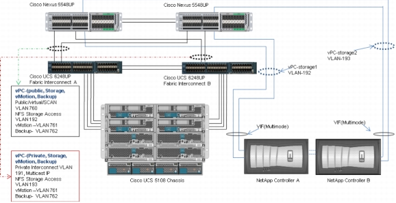
Figure 19 provides a detailed view of the physical topology, identifying the various levels of the architecture and some of the main components of Cisco UCS in an iSCSI and NFS network design.
Figure 19. Cisco UCS Components in an iSCSI and NFS Network Design
As shown in Figure 19, a pair of Cisco UCS 6248UP fabric interconnects carries both storage and network traffic from the blades with the help of the Cisco Nexus 5548UP Switch. Both the fabric interconnects and the switches are clustered with the peer link between them to provide high availability. Four virtual port channels (vPCs) are configured to provide public network, private network, and storage access paths for the blades to northbound switches. Each vPC has VLANs created for the application network data, the iSCSI storage data, and the management data paths. There is also a dedicated VLAN for VMware vMotion data traffic for the VMware ESXi Server. For more information about vPC configuration on the Cisco Nexus 5548UP Switch, see:
Figure 19 depicts four links going to Fabric Interconnect A (ports 1 through 4), and four links going to Fabric Interconnect B. The Fabric Interconnect A links handle the Oracle public network and NFS storage network traffic, and the Fabric Interconnect B links handle the Oracle private interconnect traffic and NFS storage network traffic.
Note: For the Oracle RAC configuration on Cisco UCS, Cisco recommends keeping all the private interconnects local on a single fabric interconnect with NIC failover enabled. In this configuration, the private traffic stays local to that fabric interconnect and is not routed through the northbound network switch. In other words, all interblade (or RAC node private) communication will be resolved locally at the fabric interconnect, significantly reducing latency for the Oracle cache fusion traffic.
Cisco UCS Manager Configuration Overview
This section outlines the high-level steps for configuring the Cisco UCS.
1. Configure fabric interconnects for chassis and blade discovery.
a. Configure global policies.
b. Configure server ports.
2. Configure LAN on UCS Manager.
a. Configure and enable Ethernet LAN uplink ports.
b. Configure VLAN.
3. Configure UUID and MAC pools.
a. Create UUID pool.
b. Create IP pool and MAC pool.
4. Configure vNIC templates.
a. Create vNIC templates.
b. Create public vNIC template.
c. Create private vNIC template.
d. Create storage vNIC template.
e. Create iSCSI vNIC template.
5. Configure Ethernet uplink port channels.
6. Create server boot policy for iSCSI boot.
An overview of some of the steps listed above is given in the following sections. For more information on Cisco UCS Manager configuration, see:
Configuring Fabric Interconnects for Blade Discovery
The Cisco UCS 6248UP fabric interconnects are configured for redundancy, providing resilience in case of failures. The first step is to establish connectivity between the blades and the fabric interconnects.
Configuring Global Policies
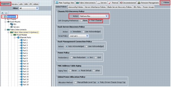
In the Cisco UCS Manager menu, choose Equipment > Policies > Global Policies, and in the Chassis/FEX Discovery Policy area, ensure that Platform Max is selected from the Action drop-down list. See Figure 20.
Note: For Cisco UCS implementations that mix I/O modules with different numbers of links, we recommend using the platform maximum value. This ensures that Cisco UCS Manager uses the maximum number of I/O module uplinks available.
Figure 20. Configuring the Global Policies
Configuring Server Ports
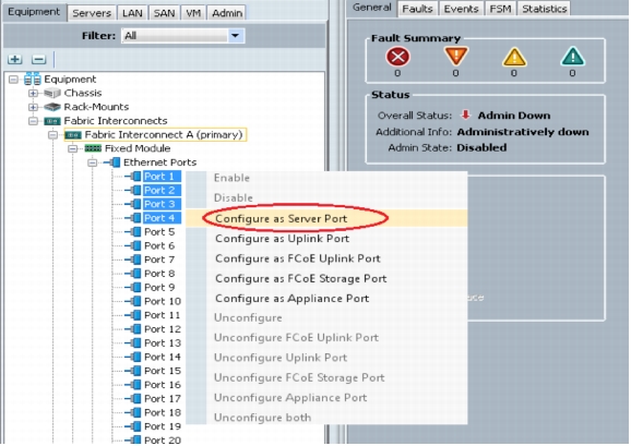
In the Cisco UCS Manager menu, choose Equipment > Fabric Interconnects > Fabric Interconnect A (primary) > Fixed Module > Ethernet Ports. Select the desired number of ports and right-click Configure as Server Port. See Figure 21.
Figure 21. Configuring Server Ports
Configuring LAN on Cisco UCS
Configuring and Enabling the Ethernet LAN Uplink Ports
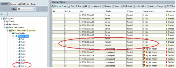
In the Cisco UCS Manager menu, choose Equipment > Fabric Interconnects > Fabric Interconnect A (primary)> Fixed Module > Ethernet Ports. Select the desired number of ports and right-click Configure as Uplink Port. See Figure 22.
Figure 22. Configuring the Ethernet LAN Uplink Ports
Figure 22 shows that ports 9 and 10 were selected on Fabric Interconnect A and configured as Ethernet uplink ports. Repeat the above steps on Fabric Interconnect B to configure ports 9 and 10 as Ethernet uplink ports.
Following are the Oracle RAC best practices and recommendations for vLAN and vNIC configuration:
• For Direct NFS clients running on Linux, it is recommended that you always use multipaths in separate subnets. If multiple paths are configured in the same subnet, the operating system invariably picks the first available path from the routing table. All traffic flows through this path, and load balancing and scaling do not work as expected.
Note: For this design configuration, VLAN 192 and VLAN 193 were created for the storage access.
• The Oracle Grid Infrastructure can activate a maximum of four private network adapters for availability and bandwidth requirements. In this testing, it was observed that a single Cisco UCS 10 Gigabit Ethernet private vNIC configured with failover did not require configuration of multiple vNICs from a bandwidth and availability perspective. If you want to configure multiple vNICs for your private interconnect, we strongly recommend using a separate VLAN for each private vNIC.
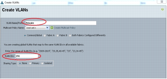
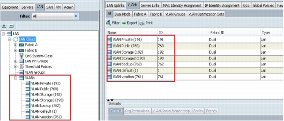
In Cisco UCS Manager, choose LAN > LAN Cloud > VLAN, and right-click Create VLANs. See Figure 23.
In this solution, six VLANs were created─one for Oracle RAC private interconnect (VLAN 191), one for the public network (VLAN 760), two for storage traffic (VLAN 192 and 193), one for vMotion (VLAN 761), and one for Oracle database backup (VLAN 762). These six VLANs will be used in the vNIC templates.
Figure 23. Creating a Private VLAN
Figure 23 shows that VLAN 191 is used to create the Oracle RAC private interconnect network. It is essential that both VLANs are created as global across both fabric interconnects. This ensures that the VLAN identity is maintained across the fabric interconnects in case of NIC failover.
Repeat the above process to create the public VLAN, the storage VLANs, the vMotion VLAN, and the backup VLAN. If you use the Oracle HAIP feature, you will need to configure additional VLANS and associate them with vNICs.
A summary of the VLANs created is as follows:
• VLAN 191 for Oracle RAC private interconnect interfaces
• VLAN 760 for public interfaces
• VLAN 192 and VLAN 193 for storage access
• VLAN 761 for vMotion
• VLAN 762 for backup of Oracle database
Figure 24 summarizes all the VLANs configured.
Note: Even though private VLAN traffic stays local within the Cisco UCS domain during normal operating conditions, it is necessary to configure entries for these private VLANS in the northbound network switch. This allows the switch to route interconnect traffic appropriately in case of partial link failures.
Figure 24. VLAN Summary
Oracle Database 11g R2 Data Network and Storage Network vPC Mapping
Table 2 describes the Cisco Nexus 5548UP vPC configurations along with the vPC domains and the corresponding vPC names and IDs for the Oracle Database servers. A pair of Cisco Nexus 5548UP Switches with upstream switching are deployed to provide Layer 2 and Layer 3 switching, helping ensure high availability so that the Cisco UCS continues to handle management, application, and network storage data traffic despite any failure. In the Cisco Nexus 5548UP Switch topology, a single vPC feature is enabled to provide high availability, faster convergence in the event of a failure, and greater throughput.
Table 2. vPC Mapping
vPC Domain
vPC Name
vPC ID
Allowed VLANs
1
Po9
9
191,192,193,760,761,762
1
Po10
10
191,192,193,760,761,762
1
Po192
192
192,193
1
Po193
193
192,193
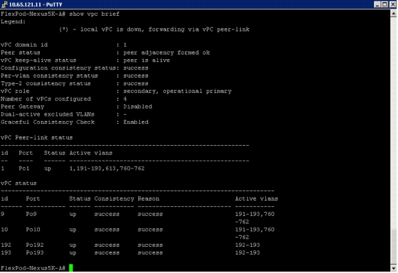
In the vPC design table, a single vPC domain, Domain 1, is created across Cisco Nexus 5548UP member switches to define the vPCs to carry the specific network traffic. This topology defines four vPCs with IDs 9,10 and 192,193. The vPC IDs 9 and 10 are defined for the network traffic from the Cisco UCS fabric interconnects, and they allow public, private, storage, vMotion, and backup network traffic, whereas vPC IDs 192 and 193 are defined for the network traffic to NetApp storage. These vPCs are managed within the Cisco Nexus 5548UP, which connects the Cisco UCS fabric interconnects and the NetApp storage system.
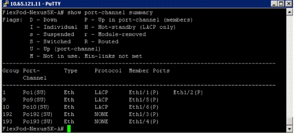
When configuring the Cisco Nexus 5548UP with vPCs, be sure that the status for all vPCs is "Up" for the connected Ethernet ports in both of the switches. Figure 25 shows the CLI commands executed and the status of all of the vPCs on one of the Cisco Nexus 5548UP Switches. Figure 26 shows the port-channel summary on Switch A.
Figure 25. vPC details and Port-Channel Status on One Cisco Nexus 5548UP
Figure 26. Port-Channel Summary on Switch A
Table 3 shows the vPC configuration details for Cisco UCS 6248UP Fabric Interconnects A and B and the required vPC IDs, VLAN IDs, and Ethernet uplink ports for the Oracle Database server data network design.
Table 3. Fabric Interconnects A and B (Oracle Database Server Data Network)
vPC Name
vPC ID
LAN Uplink Ports
VLAN ID
vPC-Public-Storage-vMotion-Backup
9
Fabric Interconnect A
(Eth 1/9 and 1/10)
760 (management), Public Access, Virtual IP, SCAN IP
192 (iSCSI Boot, NFS Storage)
193 (iSCSI Boot, NFS Storage)
761 (vMotion), 762 (Database Backup)
vPC-Private-Storage-vMotion-Backup
10
Fabric Interconnect B
(Eth 1/9 and 1/10)
191(Private Interconnect)
192 (iSCSI Boot, NFS Storage)
193 (iSCSI Boot, NFS Storage)
761 (vMotion), 762 (Database Backup)
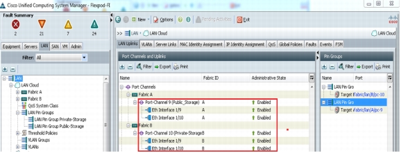
On Fabric Interconnect A, Ethernet uplink ports 9 and 10 are connected to Switch A (port 5) and Switch B (port 5), which are part of vPC ID 9, and have access to VLAN IDs 760, 761, 762, 192, and 193. Similarly, vPC ID 10 is configured on Fabric Interconnect B, with ports 9 and 10 connected to Switch A (port 6) and Switch B (port 6), with access to VLAN IDs 191, 761, 762, 192, and 193.
After configuring Cisco UCS 6248UP Fabric Interconnects A and B with vPCs, verify that the status of all of the port channels appears as "Enabled." Figure 27 shows the port-channel summary in Cisco UCS Manager.
Figure 27. Uplink Interfaces and Port-Channel Status on Fabric Interconnect
On the Cisco Nexus 5548UP Switch, a separate vPC is created to access the NetApp shared storage for the iSCSI boot as well as the NFS data access. Table 4 shows the vPC name, the corresponding vPC ID, and the required VLAN IDs.
Table 4. vPC on Nexus 5548UP for NetApp Storage Access
vPC Name
iSCSI Ports
(Controllers A and B)
vPC ID
VLAN ID
vPC-Storage1
e1a and e1b
(Controller A)
192
192
vPC-Storage2
e1a and e1b
(Controller B)
193
193
On NetApp Storage Controller A, Ethernet 10-Gbps port e1a is connected to Switch A (port 3), and Ethernet port e1b is connected to Switch B (port 3). Both ports are part of vPC-Storage1 with vPC ID 192 that allows the traffic from VLAN ID 192. On NetApp Storage Controller B, Ethernet 10-Gbps port e1a is connected to Switch A (port 4), and Ethernet port e1b is connected Switch B (port 4). Both ports are part of vPC-Storage2 with vPC ID 193 that allows the traffic from VLAN ID 193.
Cisco UCS Manager QoS System and Policy
Cisco UCS uses IEEE Data Center Bridging (DCB) to handle all the traffic within the Cisco UCS. This industry-standard enhancement to Ethernet divides the bandwidth of the Ethernet pipe into eight virtual lanes. The system classes determine how the DCB bandwidth in these virtual lanes is allocated across the entire Cisco UCS platform.
Each system class reserves a specific segment of the bandwidth for a specific type of traffic, providing an assured level of traffic management even in an oversubscribed system. For example, the Fibre Channel priority system class can be configured to determine the percentage of DCB bandwidth allocated to the FCoE traffic.
In this design solution, default QoS policy has been used for the testing purposes. However, the QoS system classes can be defined and configured to meet the solution requirements. For more information on the various QoS system classes, see Appendix A.
NetApp Storage Configuration Overview
This section explains the NetApp storage layout design considerations required to deploy Oracle Database 11g R2 RAC on a VMware ESXi hypervisor on the Cisco UCS in an NFS network environment.
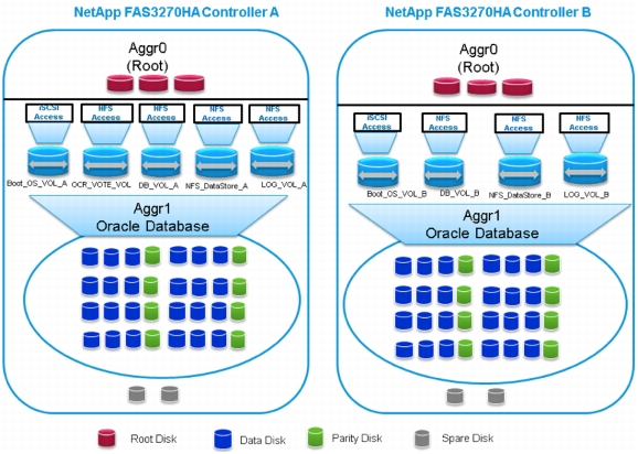
Figure 28 shows a high-level storage design overview of the NetApp FAS3270 cluster storage system.
Figure 28. Design Overview of a NetApp Storage Cluster
The NetApp aggregation layer provides a large virtualized pool of storage capacity and disk I/O operations per second (IOPS) to be used on demand by all of the virtual machines hosted on the aggregation layer. The aggregation-layer sizing is based on the storage requirements for the Oracle database to meet the storage capacity, performance, and snapshot backup requirements of a typical OLTP workload. When sizing the environment, it is essential to plan in order to determine the exact storage configuration to meet the individual requirements. Aggregation layer 0 (Aggr0) is defined for hosting the root NetApp flexible volumes (FlexVols), which use the NetApp Data ONTAP operating system for handling the NetApp storage configurations.
Table 5 lists the volumes and LUNs created for the NetApp storage layout in this design solution.
Table 5. NetApp Storage Layout with Volumes and LUNs
NetApp Storage Layout
Aggregation and NetApp Controller
NetApp FlexVol
Flexible LUN
Comments
Aggr1 on Controller A
Boot_OS_VOL_A
ESXi_OS_LUN
iSCSI boot LUN created for the VMware ESXi host
Aggr1 on Controller A
OCR_VOTE_VOL
Volume created to store the Oracle cluster registry (OCR) and the voting disk using the NFS
Aggr1 on Controller A
DB_VOL_A
Volume created to store the data files and server parameter files (SPFILE)
Aggr1 on Controller A
LOG_VOL_A
Volume created to store the redo log files and copy of the control files
Aggr1 on Controller A
NFS_DataStore_A
Volume created to store all the guest VMs
Aggr1 on Controller B
Boot_OS_VOL_B
ESXi_OS_LUN
iSCSI boot LUN created for the VMware ESXi host
Aggr1 on Controller B
DB_VOL_B
Volume created to store the data files SPFILE
Aggr1 on Controller B
LOG_VOL_B
Volume created to store the redo log files and copy of the control files
Aggr1 on Controller B
NFS_DataStore_B
Volume created to store all the guest VMs
The following commands are executed to configure the NetApp storage systems and implement the storage layout design described in this white paper:
NetApp FAS3270HA (Controller A)
• Creating an aggregate:
The following command creates Aggr1 with a RAID group size of 8, 55 disks, and RAID_DP redundancy for hosting the NetApp FlexVols and the LUNs as shown in Table 5.
The following commands create the NetApp FlexVols on Aggr1 for hosting the iSCSI LUNs and the database volumes as described in Table 5. These volumes are exposed to the VMware ESXi host and the guest virtual machines.
FAS3270HA-Controller A> vol create Boot_OS_VOL_A aggr1 200g
FAS3270HA-Controller A> vol DB_VOL_A aggr1 1024g
FAS3270HA-Controller A> vol create LOG_VOL_A aggr1 500g
FAS3270HA-Controller A> vol create OCR_VOTE_VOL aggr1 10g
FAS3270HA-Controller A> vol create NFS_DataStore_A aggr1 1024g
The following commands create the NetApp FlexVols on Aggr1 for hosting the iSCSI LUNs and the database volumes as described in Table 5. These volumes are exposed to the VMware ESXi host and the guest virtual machines.
Note: IQN names "iqn.2012-11.com.cisco:sn.100" and "iqn.2012-11.com.cisco:sn.101" are used as the iSCSI IQN names in the service profile to boot the OS using iSCSI for one of the VMware ESX servers. IQN names "iqn.2012-11.com.cisco:sn.102" and "iqn.2012-11.com.cisco:sn.103" are used as the iSCSI IQN names in the service profile to boot the OS using iSCSI for the other VMware ESX server.
• Mapping LUNS
The following command maps the LUNs to specific igroups to access the VMware ESXi host boot.
Note: LUN IDs 51 and 52 are used for the LUNs created in the steps above. The NFS exports all the flexible volumes (data volumes, redo log volumes, NFS datastore volumes, and OCR/voting disk volumes) from both Controller A and Controller B, providing read/write access to the root user of all the hosts created.
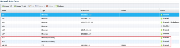
NetApp Multimode Virtual Interfaces
The NetApp multimode virtual interface (VIF) feature is enabled on the NetApp storage systems on 10 Gigabit Ethernet ports (e1a and e1b) for configuring the iSCSI target through which the OS boot LUNs are exposed over the iSCSI protocol to host the iSCSI initiators (VMware ESXi host and guest virtual machines). In this design solution, the same VIF is used to access all the flexible volumes created to store the Oracle Database files using the NFS protocol.
Creating Virtual Interfaces
The following NetApp CLI commands are executed to configure the multilevel dynamic VIF on the NetApp FAS3270HA (Controllers A and B) cluster storage systems.
NetApp FAS3270HA (Controller A)
FAS3270HA-Controller A> iscsi start
FAS3270HA-Controller A > ifgrp create VIF192 -b ip e1a e1b
FAS3270HA-Controller A > ifconfig VIF192 mtusize 9000 192.191.1.5 netmask 255.255.255.0 partner VIF193 up
NetApp FAS3270HA (Controller B)
FAS3270HA-Controller B> iscsi start
FAS3270HA-Controller B > ifgrp create VIF193 -b ip e1a e1b
FAS3270HA-Controller B > ifconfig VIF193 mtusize 9000 193.191.1.5 netmask 255.255.255.0 partner VIF192 up
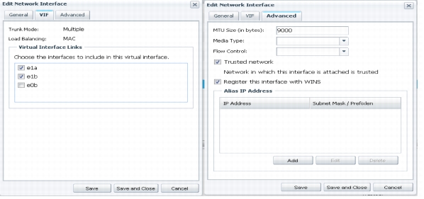
Ensure that the maximum transmission unit (MTU) is set to 9000 and that jumbo frames are enabled on the Cisco UCS static vNICs and on the upstream Cisco Nexus 5548UP Switches. Ensure that the changes are persistent.
ControllerA:: /etc/rc
Hostname CONTROLLERA
vif create VIF192 -b ip e1b e1a
ifconfig net `hostname`-net mediatype auto netmask 255.255.255.0 partner VIF193
route add default 192.191.1.1 1
routed on
options dns.domainname example.com
options dns.enable on
options nis.enable off
savecore
ControllerB:: /etc/rc
hostname CONTROLLERB
vif create VIF193 -b ip e1b e1a
ifconfig net `hostname`-net mediatype auto netmask 255.255.255.0 partner VIF192
route add default 193.191.1.1 1
routed on
options dns.domainname example.com
options dns.enable on
options nis.enable off
savecore
Figure 29 shows that VIF192 has been created, and Figure 30 shows the MTU size set to 9000 and the other properties of the VIF.
Figure 29. Virtual Interface (VIF) on NetApp Storage
Figure 30. Properties of Network Interface (VIF)
Setting up Jumbo Frames on Cisco Nexus 5548UP
The following commands are executed on the Cisco Nexus 5548UP Switches to configure the class of service (CoS) for the untagged packets originating from the NetApp storage on the port channels, and allow an MTU size of 9000 on the Cisco Nexus 5548UP Switches.
Switch A
Switch# Configure Terminal
Switch(config)# class type network-qos jumbo
Switch(config-cmap-nq)# match qos-group 5
Switch(config-cmap-nq)#policy-map type network-qos jumbo
Switch(config-pmap-nq)#class type network-qos jumbo
Switch(config-pmap-nq-c)#mtu 9216
Switch(config-pmap-nq-c)#set cos 5
Switch(config-pmap-nq)#class type network-qos class-default
Switch(config-pmap-nq-c)#mtu 9216
Switch(config-cmap-nq)#exit
Switch(config)#system qos
Switch(config-sys-qos)#service-policy type network-qos jumbo
Switch(config-sys-qos)#exit
Switch(config)# copy r s
Switch# Configure Terminal
Switch(Conf)# Interface port channel 192
Switch(Conf-if)#untagged cos 5
Switch# sh policy-map type qos
Switch# Configure Terminal
Switch(Conf)# Interface port channel 193
Switch(Conf-if)#untagged cos 4
Switch# sh policy-map type qos
Switch B
Switch# Configure Terminal
Switch(config)# class type network-qos jumbo
Switch(config-cmap-nq)# match qos-group 5
Switch(config-cmap-nq)#policy-map type network-qos jumbo
Switch(config-pmap-nq)#class type network-qos jumbo
Switch(config-pmap-nq-c)#mtu 9216
Switch(config-pmap-nq-c)#set cos 5
Switch(config-pmap-nq)#class type network-qos class-default
Switch(config-pmap-nq-c)#mtu 9216
Switch(config-cmap-nq)#exit
Switch(config)#system qos
Switch(config-sys-qos)#service-policy type network-qos jumbo
This section describes the Cisco UCS service profile design for deploying the VMware ESXi host OS booting from the NetApp shared iSCSI target on the Cisco UCS B-Series server. In this deployment, the Cisco UCS VIC 1280 adapter is used for the iSCSI boot of the VMware ESXi OS from the NetApp iSCSI target.
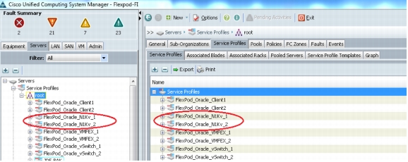
Follow the steps below to create the service profiles to deploy the VMware ESXi host OS:
1. Create the service profiles, and then associate them with the Cisco UCS B200 M3 blades. The blade server features the Cisco UCS VIC 1280 adapter to install the VMware ESXi 5.1 from the iSCSI target on the NetApp FAS3270. Figure 31 shows the list of newly created service profiles.
Figure 31. Service Profiles Summary
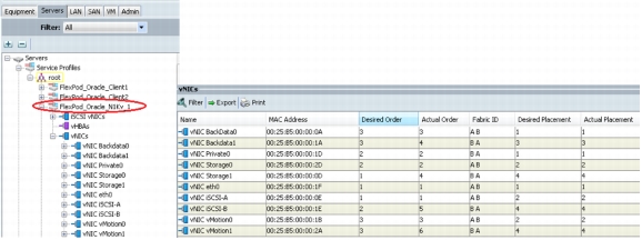
2. In each newly created service profile, 10 static vNICs are added and then associated with the respective VLAN ports. One vNIC each is associated with the public network (VLAN 760), and the private interconnect (VLAN 191); and two vNICs are associated with the storage network (VLAN 192 and 193), the iSCSI boot (VLAN 192 or 193), the vMotion network (VLAN 761), and the Oracle database backup network (VLAN 762). The public vNIC is pinned to Fabric Interconnect A, the private vNIC is pinned to Fabric Interconnect B, and the iSCSI-A and iSCSI-B are pinned to Fabric A and Fabric B, respectively. Similarly, the storage0, vMotion0, and BackData0 static vNICs are pinned to Fabric Interconnect A, and the storage1, vMotion1, and BackData1 static vNICs are pinned to Fabric Interconnect B. Set the MTU value to 9000 for all the static vNICs except the public vNIC (eth0). Figure 32 shows all the static vNICs created for each service profile.
Figure 32. Static vNICs Summary on the Fabric Interconnects
Table 6 lists the static vNICs and VLAN IDs on both of the fabric interconnects.
Table 6. Summary of the Static vNICs and VLAN IDs on the Fabric Interconnets
Static vNIC
Eth0
Private0
Storage0
Storage1
iSCSI-A
iSCSI-B
vMotion0
vMotion1
Backdata0
Backdata1
VLAN ID
760
191
192
193
192/193
192/193
761
761
762
762
MTU size
1500
9000
9000
9000
9000
9000
9000
9000
9000
9000
Fabric interconnect
A
B
A
B
A
B
A
B
A
B
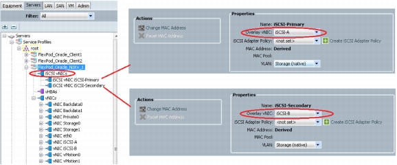
3. Create two iSCSI vNICs, iSCSI-Primary and iSCSI-Secondary, which are required to access the NetApp storage iSCSI target during the bootup process to load the VMware ESXi operating system over the iSCSI network. Ensure that iSCSI-Primary is overlaid on static vNIC iSCSI-A, and that iSCSI-Secondary is overlaid on static vNIC iSCSI-B. See Figure 33.
Figure 33. iSCSI vNICs Overlaid on Static vNICs
Note: In the iSCSI vNIC properties area, make sure that the MAC address is marked "Derived" and that the correct VLAN ID is chosen.
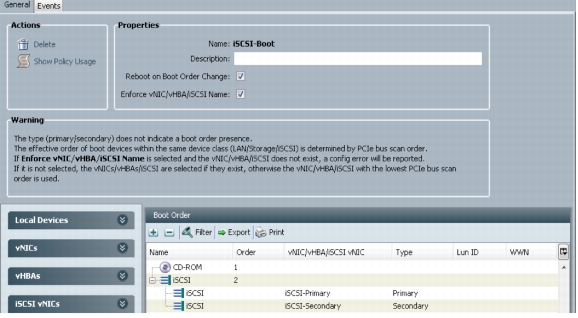
4. In Cisco UCS Manager, create a new iSCSI boot policy, Boot_iSCSI, with two iSCSI vNICs, iSCSI-Primary as the primary path and iSCSI-Secondary as the secondary path, to provide redundancy for the VMware ESXi host iSCSI boot in case of software or hardware faults. Figure 34 shows the iSCSI boot policy configuration.
Figure 34. New iSCSI Boot Policy in Cisco UCS Manager
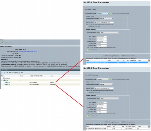
5. After the iSCSI boot policy is created, choose a newly created boot order policy for the desired service profile. On the Cisco UCS Manager Boot Order tab, choose the service profile, and assign iSCSI-Primary as the primary iSCSI vNIC and iSCSI-Secondary as the secondary iSCSI vNIC. Make sure the IQN used earlier in the "Creating an Initiator Group" step matches the IQN given in the iSCSI boot parameter. Table 7 shows the VMware ESXi iSCSI boot parameters chosen to define the iSCSI vNICs. See Figure 35.
Table 7. iSCSI Boot Parameters
iSCSI vNIC Name
iSCSI Initiator iSCSI Qualified Name (IQN)
Initiator IP Address Policy
Initiator IP Address
iSCSI Target IQN
iSCSI Port
iSCSI Target IP Address
LUN ID
iSCSI-Primary
iqn.2012-11.com.cisco:sn.100
Static
192.191.1.100
iqn.1992-08.com.netapp:sn.1574125695
3260
192.191.1.5
51
iSCSI-Secondary
iqn.2012-11.com.cisco:sn.101
Static
192.191.1.101
iqn.1992-08.com.netapp:sn.1574125695
3260
192.191.1.5
51
Figure 35. Setting iSCSI Boot Parameters
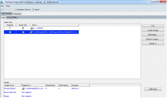
6. Associate the service profile with the desired blade (Cisco UCS B200 M3 in this case). From Cisco UCS Manager in the associated service profile, launch the keyboard, video, and mouse (KVM) console. Through the virtual media interface, click Add Image to map the VMware ESXi 5.1 ISO image from the staging area. See Figure 36.
Figure 36. KVM Console and Mapping Virtual Media
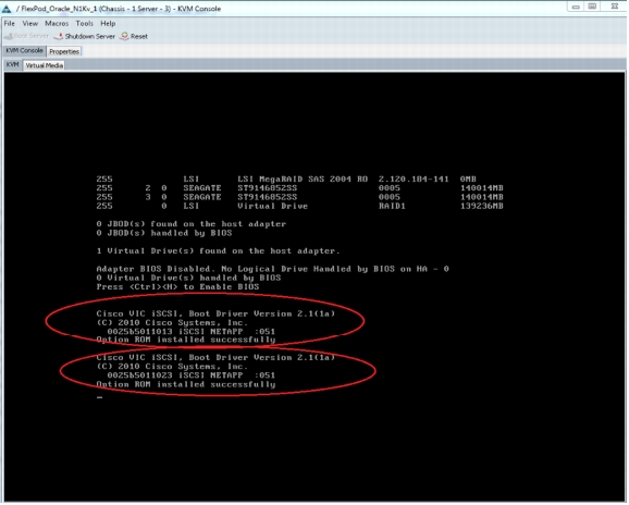
7. Click Reset to boot the server and install the operating system on the NetApp iSCSI boot LUN exposed over the iSCSI network. Figure 37 shows the LUN exposed through both paths (primary and secondary).
Figure 37. NetApp iSCSI LUN Exposed During Server Bootup
For more information about installing the OS in the iSCSI boot LUN, see:
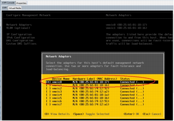
8. After the VMware ESXi OS has been installed and VMware ESXi has booted up, on the VMware ESXi console, press the F2 key to configure the management network. Under the Network Adapters option, select Ethernet port vmnic0 as it is mapped with static vNIC eth0 (compare the MAC address of static vNIC eth0 in the Cisco UCS Manager service profile) as uplink for the default VMware ESXi vSwitch named vSwitch0. See Figure 38.
Figure 38. Configuring Network Management
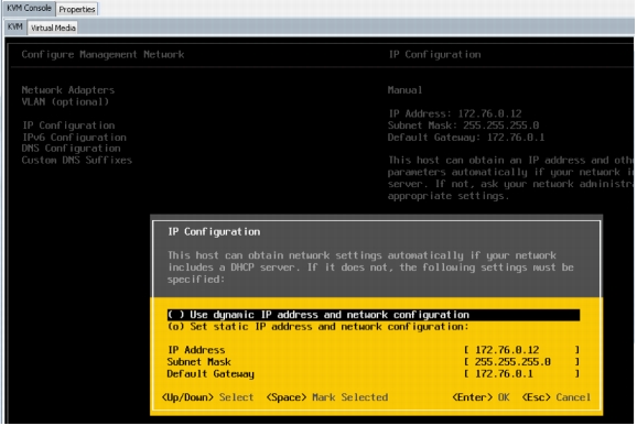
9. Under the IP Configuration option, enter the management IP address, which is on VLAN 760, associated with the VMkernel management port group. Figure 39 shows the management IP address configuration details.
Note: By default the IP address is set to the iSCSI vNIC IP address (VLAN ID 192).
Figure 39. Management IP Configuration Details
Cisco Nexus 1000V Installation and Configuration
This section explains the Cisco Nexus 1000V software switch installation and configuration for the network design to deploy Oracle Database 11g R2 RAC in the guest virtual machine running RHEL 6.2 64-bit with the VMware ESXi host. The objective of this design is to achieve high I/O throughput and high availability.
Installing Cisco Nexus 1000V
Perform the following steps to install and configure the Cisco Nexus 1000V software switch:
1. Download the Cisco Nexus 1000V 4.2(1) SV2 (1.1) software from the following location:
2. Extract the Nexus1000v.4.2.1.SV2.1.1a(1).zip file and save it on a Windows host.
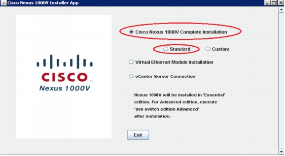
3. Run the installer file from the Windows host command prompt. The Cisco Nexus 1000V Installation Management Center is launched.
Note: The Windows host should have the latest version of Java installed.
4. Click the Cisco Nexus 1000V Complete Installation and Standard radio buttons. See Figure 40.
Figure 40. Cisco Nexus 1000V Installation Management Center
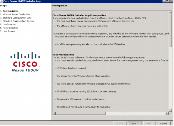
5. All the prerequisites for the installation of the Cisco Nexus 1000V are displayed. Review the prerequisites and click Next to continue. See Figure 41.
Figure 41. Displaying Prerequisites for Cisco Nexus 1000V Installation
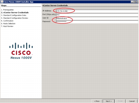
6. Enter the IP address and the credential (user ID, password) of the vCenter server. Retain the default port number. Click Next to continue. See Figure 42.
Figure 42. Entering vCenter Server Credentials
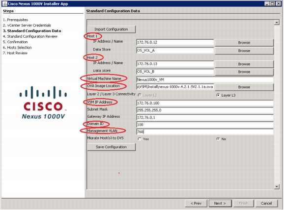
7. On the Standard Configuration Data page, enter the following information (see Figure 43):
a. Enter the IP address and the datastore name of the VMware ESX server where the primary Cisco Nexus 1000V virtual machine will be created, marked as "Host1."
b. Enter the IP address and the datastore name of the VMware ESX server where the secondary Cisco Nexus 1000V virtual machine will be created, marked as "Host2."
Note: The VMware ESX server used to install the Cisco Nexus 1000V software switches (VSM) should be separate from the VMware ESX server that is used for the Oracle RAC database consolidation.
c. Enter the virtual machine name. Browse to the OVA image location. The OVA file location is the same as the name of the Cisco Nexus 1000V binary directory. (C:\N1Kv\Nexus1000v.4.2.1.SV2.1.1a(1)\Nexus1000v.4.2.1.SV2.1.1a\VSM\Install\ nexus-1000v.4.2.1.SV2.1.1a.ova).
d. Enter the IP address, subnet mask, and gateway, along with the management VLAN ID for the virtual machine created to store the Cisco Nexus 1000V Switch.
e. Enter the domain ID (any number from 1 to 4095). It should be a unique number across all the Cisco Nexus 1000V Switches in the domain. Click Next to continue.
Figure 43. Defining Standard Configuration Data Properties
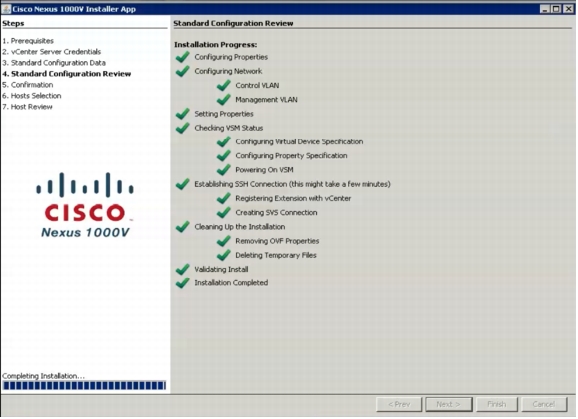
8. Review and verify the standard configuration details. Click Next to continue. See Figure 44.
Figure 44. Standard Configuration Summary
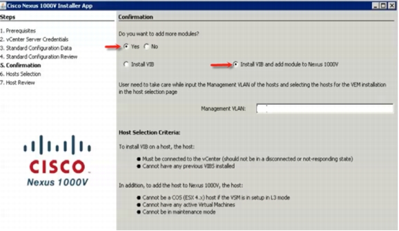
9. After the VSM installation is completed, the Confirmation page opens. Click the Yes radio button to add the VEM module. See Figure 45.
10. Click the Install VIB and add module to Nexus 1000V radio button to install the VEM module on the ESX server. All the guest VMs will be created and used for the Oracle RAC configuration on the VMware ESX server.
Figure 45. Adding Modules to the Cisco Nexus 1000V
11. In this setup, enter the management VLAN ID as 760. Click Next to continue. See Figure 46.
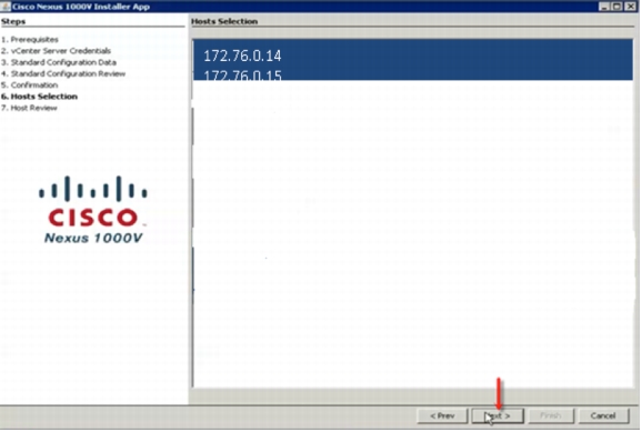
Figure 46. Selecting Hosts
12. From the list of VMware ESXi hosts displayed, select the hosts to be added to the Cisco Nexus 1000V that will be used to create all the guest VMs. Click Next to continue.
13. Review the host selection details and click Finish to install the VEM module in the VMware ESXi servers. Click Close to complete the installation.
Configuring the Cisco Nexus 1000V
To configure the VLAN for the VMware ESXi management, public network, private network, storage, and vMotion network, execute the following commands in the Cisco Nexus 1000V VSM.
1. Log in (SSH or telnet) to the Cisco Nexus 1000V VSM (IP-172.76.0.100), using the login credentials (admin/admin), and type the following configuration commands, one per line:
Note: The VLAN ID will vary depending on the network used.
N1KV_FLEXPOD(config-port-prof)# channel-group auto mode on mac-pinning
N1KV_FLEXPOD(config-port-prof)# no shutdown
N1KV_FLEXPOD(config-port-prof)# system vlan 760
N1KV_FLEXPOD(config-port-prof)#state enabled
4. Run the following commands to create the storage uplink port profile, private interconnect uplink port profile, vMotion uplink port profile, and backup database uplink port profile for the NFS traffic.
N1KV_FLEXPOD(config)# port-profile type ethernet Storage1_Uplink
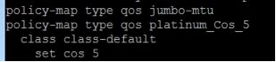
N1KV_FLEXPOD(config-port-prof)# service -policy type qos input platinum_Cos_5
N1KV_FLEXPOD(config-port-prof)# no sh
N1KV_FLEXPOD(config-port-prof)# system vlan 762
N1KV_FLEXPOD(config-port-prof)#state enabled
N1KV_FLEXPOD# copy running-config startup-config
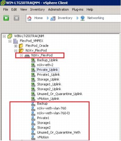
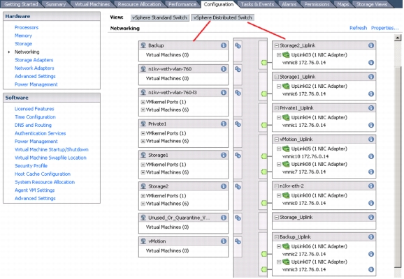
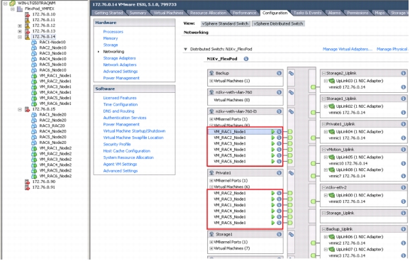
After creating the port profiles, verify all the port profiles and port groups under the respective Cisco Nexus 1000V VSM in the vCenter. See Figure 47.
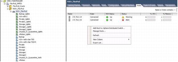
1. Choose Inventory >Networking >DVS, and click on the Hosts tab. Right-click Add Host to vSphere Distributed Switch to add the host. See Figure 48.
Figure 48. Adding a Host to the vSphere Distributed Switch
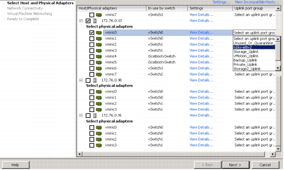
2. On the Select Host and Physical Adapters page, select the host to add to the vSphere distributed switch. Select the uplink port group for the host selected. See Figure 49.
Figure 49. Selecting the Host to Add
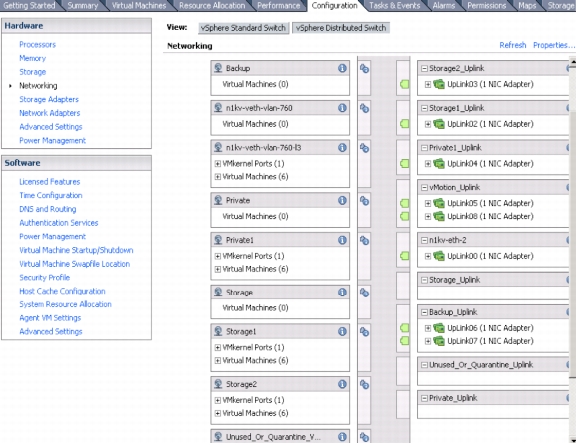
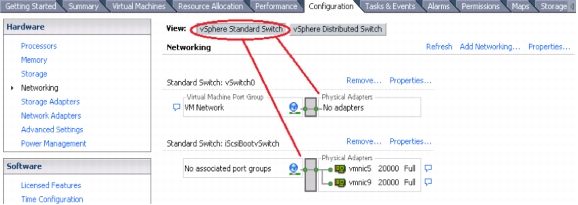
3. All the VMware ESXi hosts are managed through the Cisco Nexus 1000V Switch, after the VMware ESXi host is added and all the vmnics are mapped to the respective port groups. To verify the VMware ESXi hosts, choose ESXi Host > Configuration > Networking. See Figure 50.
Figure 50. Verifying the Configuration
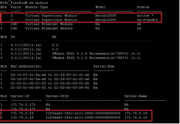
4. Log in to the Cisco Nexus 1000V Switch and run the show module command to verify the IP addresses of the VMware ESXi hosts managed through the Cisco Nexus 1000V Switch. See Figure 51.
Figure 51. Verifying the IP Addresses
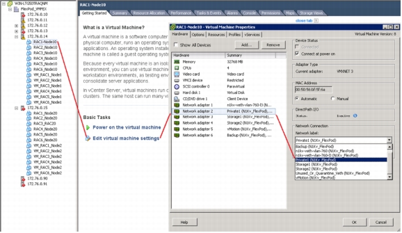
Table 8 shows the properties of the static vNICs created for the service profile and mapped to the respective port groups in the vCenter server for each VMware ESXi server.
Table 8. Cisco UCS Manager Service Profile's Static vNICs and Cisco Nexus 1000V Port Groups
vNIC Name
Fabric ID
Failover
Adapter Policy
VLAN
MAC Address
QoS
N1kv Port group
VMwareESX VMNIC
eth0
Fabric A
Yes
VMware
760
00:25:B5:00:00:01
Default
n1kv-eth2
vmnic0
Private
Fabric B
Yes
VMware
191
00:25:B5:00:00:02
Default
Private
vmnic1
Storage1
Fabric A
No
VMware
192
00:25:B5:01:01:02
Default
Storage1
vmnic6
Storage2
Fabric B
No
VMware
193
00:25:B5:02:01:02
Default
Storage2
vmnic8
vMotion1
Fabric A
No
VMware
761
00:25:B5:01:02:02
Default
vMotion
vmnic7
vMotion2
Fabric B
No
VMware
761
00:25:B5:01:01:01
Default
vMotion
vmnic10
Backup1
Fabric A
No
VMware
762
00:25:B5:02:01:02
Default
Backup
vmnic2
Backup2
Fabric B
No
VMware
762
00:25:B5:01:02:01
Default
Backup
vmnic3
iSCSI-A
Fabric A
No
VMware
192/193
00:25:B5:01:01:01
Default
-
vmnic5
iSCSI-B
Fabric B
No
VMware
192/193
00:25:B5:01:01:02
Default
-
vmnic9
Note: The two uplink ports, vmnic5 and vminc9, of the iSCSI Boot port group of iScsiBootvswitch should be left undisturbed. Altering these settings can affect the VMware ESXi bootup through the iSCSI LUNs. See Figure 52 and Figure 53.
The following steps are used to create the guest virtual machines used to deploy Oracle 11g R2 RAC:
1. Log in to the VMware vCenter server and select the VMware ESXi server.
2. Click Create a New virtual machine to create a guest virtual machine.
3. Select the appropriate number of vCPUs and the size of memory for the guest virtual machine.
Make sure to add six network adapters in each guest virtual machine (one for public access, one for private interconnect, two for storage access from NFS Storage, one for vMotion, and one for backup of the Oracle Database). Figure 54 shows the guest VMs and their network adapter settings.
Install the guest operating system RHEL 6.2 64-bit with all the required RPMs for Oracle Database 11g R2 RAC in each of the guest virtual machines. Also define the IP address for each network adapter in each guest VM with the appropriate MTU size. (For public access, MTU is set to 1500; for private interconnect, storage access, vMotion, and backup network adapters, MTU is set to 9000.) See Figure 55.
Figure 55. Configuring Each Network Interface on the Guest Virtual Machine
The VMware ESXi vCenter provides a single pane to view all the guest virtual machines and port groups. The pane also shows the port ID, the link connectivity status, and the Cisco UCS port profile information applied, with the MAC address, the MTU, and the IP address configured in the RHEL 6.2 64-bit guest VM. See Figure 56.
Figure 56. Link Connectivity Status and Cisco UCS Port Profile Information
Oracle Database 11g R2 RAC Deployment
This section describes the deployment of Oracle Database 11g R2 RAC in a virtualized environment. After installing the guest OS RHEL 6.2 64-bit in each of the RAC nodes, verify that all the required RPMs are installed as part of the guest OS installation, which is required for the Oracle Database 11g R2 RAC installation.
For more information on pre-installation tasks, such as setting up the kernel parameters and RPM packages and creating users, see:
This white paper elaborates on the steps to create the user, group, directory structure, kernel parameters, and user limits. The kernel parameter and user limits can be resized, while the directory structure, user name, and groups can be renamed to meet the business requirements.
Follow these steps to install Oracle Database 11g R2 RAC:
1. Create the required number of Oracle users and groups in each RAC node.
groupadd -g 1000 oinstall
groupadd -g 1200 dba
useradd -u 2000 -g oinstall -G dba grid
passwd grid
useradd -u 1100 -g oinstall -G dba oracle
passwd oracle
2. Create the local directories on each RAC node, and give the ownership of these directories to the users created in the previous step.
Table 9 shows the mapping of the NFS volumes with the newly created directory in each Oracle RAC node.
Table 9. Local Mount Points and NetApp NFS Volumes
Local Directory on Guest OS
NetApp NFS Volumes
Owner
Purpose
/u01/app/oracle
local
Oracle
Oracle Database binary installation
/data_A
/vol/RAC1_DATA_A
Oracle
Data files
/data_B
/vol/RAC1_DATA_B
Oracle
Data files
/log_A
/vol/RAC1_LOG_A
Oracle
Redo log files and control files
/log_B
/vol/RAC1_LOG_B
Oracle
Redo log files and control files
/ocrvote
/vol/RAC1_OCR_VOTE
Grid
OCR and voting disks
3. Edit the /etc/fstab file in each RAC node and add the entry for all the volumes and their corresponding local directories created in step 2 with the appropriate mount options. See Figure 57.
Figure 57. Mount Options Used to Mount NFS Volumes
To find the proper mount options for different file systems of the Oracle Database 11g R2 RAC, see:
Note: The rsize and wsize of 65536 is supported by NFS v3 and is used in this configuration to improve performance.
4. Configure the public, private, storage, vMotion, and backup network interfaces with the appropriate IP addresses of the respective VLANs.
5. Mount all the local directories created to store the Database, the OCR file, and the voting disks by editing the /etc/fstab file in each RAC node using the root user.
node1# mount /ocrvote
node1# mount /data_A
node1# mount /data_B
node1# mount /log_A
node1# mount /log_B
Give ownership of mounted directories to appropriate user.
Identify the virtual IP addresses and the SCAN IPs and have them set up in the DNS as per Oracle's recommendation. Alternatively, update the /etc/hosts file with all the details (private, public, SCAN, and virtual IP) if the DNS services are not available.
6. Create files for OCR and voting devices under /ocrvote local directories as follows:
Log in as the "grid" user from any of the nodes and create the following raw files:
7. Configure the SSH option (with no password) for the oracle and grid users.
For more information about SSH configuration, see the Oracle installation documentation.
Note: The Oracle Universal Installer also offers automatic SSH connectivity configuration and testing.
8. Configure the /etc/sysctl.conf file by adding shared memory and semaphore parameters required for the Oracle Grid installation. Also configure the /etc/security/limits.conf file by adding user limits for the oracle and grid users.
Configuring HugePages
HugePages is a method to have a larger page size, which is useful for working with very large memory. For Oracle Databases, using HugePages reduces the operating system maintenance of page states and increases the translation lookaside buffer (TLB) hit ratio.
HugePages offer the following advantages:
• They are not swappable, so there is no page-in/page-out mechanism overhead.
• Fewer pages are required to cover the physical address space, so the amount of "bookkeeping" (mapping from the virtual to the physical address) decreases, requiring fewer entries in the TLB and therefore improving the TLB hit ratio.
• Page table overhead is reduced.
• Page table lookup overhead is eliminated: Since the pages are not subject to replacement, page table lookups are not required.
• Overall memory performance is faster: On virtual memory systems each memory operation is actually two abstract memory operations. Since there are fewer pages to work on, the possible bottleneck due to page table access is clearly avoided.
For the current configuration, HugePages was used for the OLTP workload. For information on HugePages, see: Oracle metalink document 361323.1
Installing Oracle Database 11g R2 RAC and the Database
It is not within the scope of this document to include the details of the Oracle RAC installation. For specific installation instructions for Oracle RAC, see the Oracle installation documentation.
To install Oracle RAC, follow these steps:
1. Download the Oracle Database 11g R2 RAC Infrastructure (11.2.0.3.0) and Oracle Database 11g R2 (11.2.0.3.0) for Linux x86-64.
Note: In the current configuration, NFS shared volumes were used for the OCR files and voting disks for the Oracle Grid Infrastructure installation.
2. On the Storage Option Information page, click the Shared File System radio button to define where the OCR files and voting disks files can be placed. Click Next. See Figure 58.
Figure 58. Placing OCR Files and Voting Disks on a Shared File System
3. On the OCR Storage Option page, enter the OCR file names and directory path created in the previous section. See Figure 59.
Figure 59. Defining the OCR File Names and Directory Path
4. On the Voting Disk Storage page, enter the voting disk file names and directory path created in the previous section. See Figure 60.
Figure 60. Defining the Voting Disk File Names and Directory Path
5. After the Oracle Grid installation is complete, install the Oracle Database 11g R2 "Software Only."
Do not create the database as the oracle user following the Oracle Grid installation. For detailed information on the Oracle RAC installation for Linux and UNIX, see:
6. Run the Database Configuration Assistant (DBCA) tool as the oracle user to create the OLTP Database. Ensure that the data files, redo logs, and control files are placed in the proper directory paths created in the previous steps.
Configuring the Direct NFS Client
For improved NFS performance, Oracle recommends using the Direct NFS client shipped with Oracle Database 11g R2 RAC. The Direct NFS client looks for NFS details in the following locations:
• $ORACLE_HOME/dbs/oranfstab
• /etc/oranfstab
• /etc/mtab
In the Oracle RAC configuration with Direct NFS, oranfstab must be configured in all the nodes. The oranfstab configuration from RAC node 1 is listed below:
[oracle@orarac1 dbs]$ vi oranfstab
server:192.191.1.5
path:192.191.1.5
local:192.191.1.101
local:193.191.1.101
server:193.191.1.5
path:193.191.1.5
local:193.191.1.101
local:192.191.1.101
export:/ocrvote mount:/vol/RAC1_OCR_VOTE
export:/log_A mount:/vol/RAC1_LOG_A
export:/log_B mount:/vol/RAC1_LOG_B
export:/data_A mount:/vol/RAC1_DATA_A
export:/data_B mount:/vol/RAc1_DATA_B
Since the NFS mount point details were defined in the /etc/fstab file, and therefore also in the /etc/mtab file, there is no need to configure any extra connection details. When setting up the NFS mounts, refer to the Oracle documentation to ascertain the types of data that can and cannot be accessed through the Direct NFS client.
For the client to work, switch the libodm11.so library to the libnfsodm11.so library, using the oracle binary owner user, as described below:
srvctl stop database -d rac1db
cd $ORACLE_HOME/lib
mv libodm11.so libodm11.so_stub
ln -s libnfsodm11.so libodm11.so
srvctl start database -d rac1db
Note: For Oracle 11g R2, Direct NFS can also be enabled by using the command make -f ins_rdbms.mk dnfs_on.
Direct NFS client usage can be seen using the following views:
• v$dnfs_servers
• v$dnfs_files
• v$dnfs_channels
• v$dnfs_stats
An example from the OLTP Database configuration is given below;
Note: The Direct NFS client supports direct I/O and asynchronous I/O by default.
Scaling and Consolidation of Two-Node Oracle Database 11g R2 RAC
This section elaborates on the scaling and consolidation of two-node Oracle Database 11g R2 RAC on the FlexPod using the Cisco Nexus 1000V and the Cisco VICs. Two fully loaded Cisco UCS B200 M3 Blade Servers were used. Three different consolidation scenarios can be implemented for the Oracle 11g R2 RAC deployment.
Scenario 1: Set up a two-node Oracle cluster by using one guest virtual machine from each VMware ESXi server and two instances of the database running on the same Oracle cluster. In this scenario, Oracle clusters are added one by one, and then a database is created for each Oracle cluster. Figure 61 shows Scenario 1 with multiple Oracle 11g R2 Databases and multiple RAC consolidation.
Figure 61. Scenario 1: Guest VM in Every Blade and Multiple Oracle Cluster Configurations
Scenario 2: Set up one single largest Oracle cluster by using all the guest virtual machines from both of the VMware ESXi servers. Create each database on two nodes by selecting one guest VM from each VMware ESXi server. Figure 62 shows Scenario 2 for the Oracle 11g R2 Database with RAC consolidation and guest VM configuration.
Scenario 3: Create one large virtual machine in each VMware ESXi server. Set up a two-node Oracle cluster by using the large guest VM from both VMware ESXi servers. Create each database on the two-node Oracle cluster. Figure 63 shows Scenario 3 for the Oracle 11g R2 Database with RAC consolidation and the guest VM configuration.
In this design solution, Scenario 1 was used to consolidate the multiple Oracle clustered Databases. Six databases with a size of 500 GB were consolidated with their independent Oracle cluster, considering optimal utilization of CPU, memory, and network in each of the VMware ESXi servers as well as storage.
Each VMware ESXi OS is an iSCSI boot from the NetApp storage and the NFS protocol that is used to access data volumes and guest OS volumes from the NetApp storage. RHEL 6.2 64 bit is installed on every guest virtual machine.
Table 10 shows the configuration of the guest virtual machines.
Table 10. Guest Virtual Machine Configuration
Guest VM Component
Details
Description
CPU
4 vCPUs
4 dynamic virtual CPUs
Memory
32 GB
Physical memory
NIC1
Public access
MTU size 1500 for the management and public access
NIC2
Private interconnect
Oracle private interconnect configured; MTU size 9000
NIC3
NFS Storage Access1
Database access through NFS; MTU size 9000
NIC4
NFS Storage Access2
Database access through NFS; MTU size 9000
NIC5
Dedicated for vMotion
Used for vMotion; MTU size 9000
NIC6
Dedicated for database backup
Used for database backup; MTU size 9000
SWAP space
32 GB
Swap space
Scenarios 2 and 3 can also be implemented, depending on the customer requirements. The Oracle Database binary and Oracle Grid Infrastructure are installed in the local storage of each guest virtual machine; however, these binaries can be installed in a shared NFS storage also. The database data file, redo log files and CRS, and voting disks are stored in NetApp storage and accessed through NFS.
Table 11 shows the configuration of the directory structure created in each of the guest virtual machines to store the database as well as the binaries.
Table 11. Guest Virtual Machine Local Directory Configuration for Each Oracle Cluster
Guest VM Directory
Details
Description
/u01/app/oracle
Locally created
Database binary
/u01/app/11.2.0/
Locally created
Grid Infrastructure
/ocrvote
Mounted with NFS volume
OCR file and voting disk
/data_A
Mounted with NFS volume from Controller A
Data files
/data_B
Mounted with NFS volume from Controller B
Data files
/log_A
Mounted with NFS volume from Controller A
Redo log files and copy of the control file
/log_B
Mounted with NFS volume from Controller B
Redo log files and copy of the control file
Table 12 shows the storage configuration required for each Oracle cluster to store the 500 GB required for the database.
Table 12. Storage Configuration for Database
Aggregate Name
Storage Controller
Volume Name
Size
Description
Aggr1
Controller A
/vol/RAC1_DATA_A
350 GB
Data files
Aggr1
Controller A
/vol/RAC1_LOG_A
100 GB
Redo logs and copy of control file
Aggr1
Controller A
/vol/RAC1_OCR_VOTE
20 GB
OCR file and voting disk
Aggr1
Controller B
/vol/RAC1_DATA_B
350 GB
Data files
Aggr1
Controller B
/vol/RAC1_LOG_B
100 GB
Redo logs and copy of control file
Workloads and Database Configuration
This section elaborates on the workloads and the database configuration used in the design solution.
Order Entry Benchmark (OLTP)
In this design solution, Swingbench is used for workload testing. Swingbench is a simple-to-use, free, Java-based tool used to generate a database workload and perform stress testing using various benchmarks in the Oracle Database environment. Swingbench provides four separate benchmarks: Order Entry, Sales History, Calling Circle, and Stress Test. In the workload testing described in this section, the Swingbench Order Entry benchmark was used. The Order Entry benchmark is based on the SOE schema and resembles the TPC-C benchmark with respect to types of transactions. The workload uses a very balanced read-to-write ratio of 60 to 40 and can be designed to run continuously and test the performance of a typical order entry workload against a small set of tables, producing contention for database resources.
The next step is to precreate the order entry for the OLTP workload. The Swingbench Order Entry workload uses SOE tablespace. The schemas are precreated to associate multiple data files with tablespaces and also to evenly distribute them across two storage controllers. In the current setup, 24 data files were created for the SOE tablespace, with odd-numbered files for Storage Controller A and even-numbered files for Storage Controller B.
OLTP Database
The OLTP Database was populated with the following data:
[oracle@orarac1 ~]$ sqlplus soe/soe
SQL*Plus: Release 11.2.0.3.0 Production on Wed Mar 27 12:02:01 2013
Copyright (c) 1982, 2011, Oracle. All rights reserved.
Connected to:
Oracle Database 11g Enterprise Edition Release 11.2.0.3.0 - 64bit Production
With the Partitioning, Real Application Clusters, Oracle Label Security, OLAP,
Data Mining, Oracle Database Vault and Real Application Testing options
SQL> select table_name, num_rows from user_tables;
TABLE_NAME NUM_ROWS
------------------------------ ----------
CUSTOMERS 520000000
ORDER_ITEMS 1754994009
ORDERS 610109066
LOGON 194035834
ORDERENTRY_METADATA 4
PRODUCT_DESCRIPTIONS 1000
PRODUCT_INFORMATION 1000
INVENTORIES 901977
WAREHOUSES 1000
Performance Data
This section presents an analysis of the tests conducted in this design solution.
Each database carried 350 concurrent OLTP users issuing transactions at a predefined rate, and the same transaction rate was observed when six Oracle clustered databases were deployed on the same physical blade server (Cisco UCS B200 M3).
Linear scaling of the Oracle cluster node was verified during the test. After the addition of one Oracle RAC Database after another, linear utilization of the VMware ESXi host as well as the NetApp storage was observed.
Figure 64 shows the linear scaling of the VMware ESXi server CPU utilization and the transactions per minute when each Oracle RAC Database was added. The NFS response time observed was less than 3 milliseconds, and the transaction response time observed was less than 25 milliseconds.
Figure 64. CPU and Transactions per Minute for Databases Added in Succession
Figure 65 shows the storage CPU and storage disk utilization, along with the IOPS generated from the storage after each Oracle RAC Database was added. The IOPS observed are the combined IOPS generated both from the Flash Cache and the disks.
Figure 65. Storage CPU, Disk Utilization, and IOPS for Databases Added in Succession
Summary
FlexPod combines various technologies, mainly the Cisco Unified Computing System, VMware vSphere 5.1, and NetApp storage technologies, to form a highly reliable, robust, and virtualized solution for Oracle Database 11g R2 RAC.
Oracle Database 11g R2 RAC consolidation using virtualization technology has tremendous benefits for optimizing data center resources. FlexPod provides an ideal platform for Oracle RAC Database consolidation. Cisco's unique technologies, such as Cisco Extended Memory technology, Cisco Virtual Interface Cards, and the Cisco Nexus 1000V Switch, enable an exceptional level of consolidation that stands out in the industry for this class of platform, thereby resulting in significantly improved ROI and lower TCO for IT managers.
Here's what makes the combination of Cisco UCS with NetApp storage so powerful for Oracle environments:
• The stateless computing architecture provided by the service profile capability of the Cisco UCS allows for fast, nondisruptive workload changes to be executed simply and seamlessly across the integrated Cisco UCS infrastructure and the Cisco x86 servers.
• Cisco UCS, combined with a highly scalable NAS platform from NetApp, provides the ideal combination for Oracle's unique, scalable, and highly available NFS technology.
• All of this is made possible by Cisco's Unified Fabric, with its focus on secure IP networks as the standard interconnect for server and data management solutions.
This white paper introduced two-node Oracle Database 11g R2 RAC validation and consolidation of multiple databases on FlexPod in a virtualized environment. Linear scaling of resource utilization was observed for both storage as well as the server while consolidating multiple Oracle RAC Databases. In this design solution, Scenario 1 was used for the two-node Oracle Database 11g R2 RAC scaling and consolidation study. Six Oracle RAC Databases sized 500 GB each were consolidated in a pair of Cisco UCS B200 M3 servers.
The Cisco Nexus 1000V technology employed in this solution is compatible with VMware vSphere as a VMware vNetwork distributed switch (vDS), as it supports the VMware ESX and the ESXi hypervisors and integrates efficiently with the VMware vCenter server.
In addition to the traditional switching capability, the Cisco Nexus 1000V Switch offers the Cisco vPath architecture to support virtualized network services, while the Cisco VN-Link technology provides a common management model for both physical and virtual network infrastructures through policy-based virtual machine connectivity, mobility of virtual machine security and network properties, and a nondisruptive operational model.
The Cisco server fabric switch enables utility computing by dramatically simplifying the data center architecture. It creates a unified, "wire-once" fabric that aggregates I/O and server resources. With the unified fabric, instead of servers having many cables attached to them, the server switch connects every server with a single high-bandwidth, low-latency network cable (two cables for redundancy).
Aggregating the server's I/O resources saves significant capital expense. Consolidating resources over the unified fabric eliminates the costs of underutilized Fibre Channel HBAs and NICs, as well as the associated cabling complexity. Instead of being designed to accommodate bandwidth peaks using a dedicated switch port for each host, a data center can share remote Fibre Channel and Gigabit Ethernet ports, enabling network designs based on average load across multiple servers. This can save up to 50 percent of the cost of the I/O associated with a server. Also, eliminating multiple adapters and local storage by introducing a single high-bandwidth, low-latency connection means that the size of the server is driven only by CPU and memory requirements. This often results in a reduction in the size and cost of the server as well as in its space, power, and cooling needs, resulting in immediate ROI savings of up to 50 percent.
Bill of Materials
Table 13, Table 14, and Table 15 detail the components used in this solution design.
Table 13. Hardware Components Used in the Deployment
Server Details
Storage Details
4 Cisco UCS B200 M3 Blade Servers
NetApp FAS 3270
CPU: Intel Xeon E5-2690
Protocol license: NFS, iSCSI
Memory: 256 GB
Network: 10-Gbps Ethernet and iSCSI
Network: VIC adapter with 80-Gbps bandwidth
Flash Cache: Two 500 GB
Server role: VMware ESXi Server hosting guest VM for Oracle Database 11g R2 Grid with RAC option
Type and number of disk drives: 144 SAS 15,000 rpm
Table 16 describes the various system classes that can be used to meet the design solution requirements.
Table 16. System Classes
System Class
Description
• Platinum priority
• Gold priority
• Silver priority
• Bronze priority
These classes set the quality of service (QoS) defined in the service profiles associated with any or all the servers. Each of these system classes manages one lane of traffic. All the properties of these system classes are available and can be used to assign custom settings and policies to the server.
Best-Effort priority
This class sets the QoS for the lane that is reserved for basic Ethernet traffic. Some of the properties in this system class are preset and cannot be modified. For example, this class offers a drop policy that allows it to drop data packets if required.
Fibre Channel priority
This class sets the QoS for the lane that is reserved for FCoE traffic. Some of the properties in this system class are preset and cannot be modified. For example, this class offers a no-drop policy that ensures that it never drops data packets.
The QoS system classes and the corresponding policies enable efficient network utilization and bandwidth control in an Oracle Database 11g R2 RAC environment on VMware ESXi over an NFS network. The QoS system classes and the corresponding policies defined for the network traffic generated by the NFS storage, VMware vMotion, Oracle Database 11g R2 RAC, and the guest virtual machine management network in Cisco UCS are as follows:
• The Oracle Clusterware heartbeat requires high bandwidth and a fast response for the cache fusion and the interconnect traffic. To meet this requirement, a RAC_HB QoS policy is created and defined with the Platinum class. This class is assigned the highest weight (bandwidth) and an MTU of 9000.
• The NFS storage traffic requires reasonable bandwidth and a fast response time to access the Oracle Database (data files and redo log files) stored in the shared storage. To meet this requirement, an OracleDB QoS policy is created with the Gold class. This class is assigned the second highest weight (bandwidth) and an MTU of 9000.
• The iSCSI boot for the VMware ESXi kernel requires dedicated network bandwidth to boot the VMware ESXi host from the NetApp storage. To meet this requirement, iSCSI_Boot QoS policy is created and is defined with the Silver class. This class is assigned with the third highest weight (bandwidth) and an MTU of 9000 to handle the jumbo VMkernel packets from the vNICs (static) in the service profiles in which the VMware ESXi host is installed, which is a part of the VMware ESXi host-based iSCSI environment.
• To handle the VMware vMotion kernel traffic across a VMware ESX cluster during dynamic resource scheduler or manual intervention, VMware ESX requires dedicated network bandwidth for copying virtual machine active memory data. To meet this requirement, vMotion QoS policy is created and is defined with the Bronze class, which has the third highest weight (bandwidth) and an MTU of 9000 to handle jumbo VMkernel packets from the vNICs (static) in the service profiles in which the VMware ESX host is installed.
• To handle the VMware ESXi host and guest virtual machine network traffic, for management and operations that have lower bandwidth requirements, the Best-Effort QoS class with the least weight (bandwidth) is defined on Cisco UCS.
Note: To achieve end-to-end QoS across the system, the QoS class and policy types defined for the Cisco Nexus 5548UP Switches should be configured with class-of-service (CoS) values that match the Cisco UCS QoS classes.
Table 17 shows the QoS policy names with the corresponding priority, weight, and MTU value. These values are applied to static and dynamic vNICs in the Oracle Database 11g R2 RAC environment. Table 18 shows the QoS mapping values for Cisco UCS and the Cisco Nexus 5548UP Switch.