Feedback
Contents
- Managing Mesh Access Points with Cisco Prime Infrastructure
- Adding Campus Maps, Outdoor Areas, and Buildings with Cisco Prime Infrastructure
- Adding Campus Maps
- Adding Outdoor Areas
- Adding a Building to a Campus Map
- Adding Mesh Access Points to Maps with Cisco Prime Infrastructure
- Monitoring Mesh Access Points Using Google Earth
- Launching Google Earth in Cisco Prime Infrastructure
- Viewing Google Earth Maps
- Adding Indoor Mesh Access Points to Cisco Prime Infrastructure
- Managing Mesh Access Points with Cisco Prime Infrastructure
- Monitoring Mesh Networks Using Maps
- Monitoring Mesh Link Statistics Using Maps
- Monitoring Mesh Access Points Using Maps
- Monitoring Mesh Access Point Neighbors Using Maps
- Monitoring Mesh Health
- Viewing Mesh Statistics for a Mesh Access Point
- Viewing the Mesh Network Hierarchy
- Using Mesh Filters to Modify Map Display of Maps and Mesh Links
- Monitoring Workgroup Bridges
- Multiple VLAN and QoS Support for WGB Wired Clients
- Workgroup Bridge Guidelines
- Configuring VLAN and QoS Support (CLI)
- Workgroup Bridge Output
- WGB Detail on Controller
- Troubleshooting Tips
- Viewing AP Last Reboot Reason
Managing Mesh Access Points with Cisco Prime Infrastructure
This chapter describes how to manage mesh access points with Cisco Prime Infrastructure.
To configure and monitor mesh networks from Cisco Prime Infrastructure, you must first import campus and outdoor maps into the Prime Infrastructure and add buildings. Thereafter, you can add mesh access points to the map and configure and monitor mesh access points from the Prime Infrastructure.
This chapter contains the following sections:
- Adding Campus Maps, Outdoor Areas, and Buildings with Cisco Prime Infrastructure
- Adding Mesh Access Points to Maps with Cisco Prime Infrastructure
- Monitoring Mesh Access Points Using Google Earth
- Adding Indoor Mesh Access Points to Cisco Prime Infrastructure
- Managing Mesh Access Points with Cisco Prime Infrastructure
- Monitoring Workgroup Bridges
- Viewing AP Last Reboot Reason
Adding Campus Maps, Outdoor Areas, and Buildings with Cisco Prime Infrastructure
For mesh networks, maps and items on those maps (buildings and mesh access points) are added to Cisco Prime Infrastructure in the following order:
Adding Campus Maps
Adding Outdoor Areas
To add an outdoor area to a campus map, follow these steps:
NoteYou can add outdoor areas to a campus map in the Cisco Prime Infrastructure database regardless of whether you outdoor area maps are in the database.
Step 1 If you want to add a map of the outdoor area to the database, save the map in .PNG, .JPG, .JPEG, or .GIF format. Then browse to and import the map from anywhere in your file system.
Note You do not need a map to add an outdoor area. You can simply define the dimensions of the area to add it to the database. The map can be any size because Cisco Prime Infrastructure automatically resizes the map to fit the workspace.
Step 2 Choose Monitor > Maps to display the Maps page. Step 3 Click the desired campus. Cisco Prime Infrastructure displays the Maps > Campus Name page. Step 4 From the Select a command drop-down list, choose New Outdoor Area and click GO. Step 5 On the Campus Name > New Outdoor Area page, follow these steps to create a manageable outdoor area:
Step 6 Click Save.
Adding a Building to a Campus Map
You can add buildings to the Cisco Prime Infrastructure database regardless of whether you have added campus maps to the database. This section explains how to add a building to a campus map or a standalone building (one that is not part of a campus) to the Prime Infrastructure database.
To add a building to a campus map in the Prime Infrastructure database, follow these steps:
Step 1 Choose Monitor > Maps to display the Maps page. Step 2 Click the desired campus. Cisco Prime Infrastructure displays the Maps > Campus Name page. Step 3 From the Select a command drop-down list, choose New Building and click Go. Step 4 On the Campus Name > New Building page, follow these steps to create a virtual building in which to organize related floor plan maps:
Step 5 Click Save.
Adding Mesh Access Points to Maps with Cisco Prime Infrastructure
After you add the .PNG, .JPG, .JPEG, or .GIF format floor plan and outdoor area maps to the Cisco Prime Infrastructure database, you can position mesh access point icons on the maps to show where they are installed in the buildings.
To add mesh access points to floor plan and outdoor area maps, follow these steps:
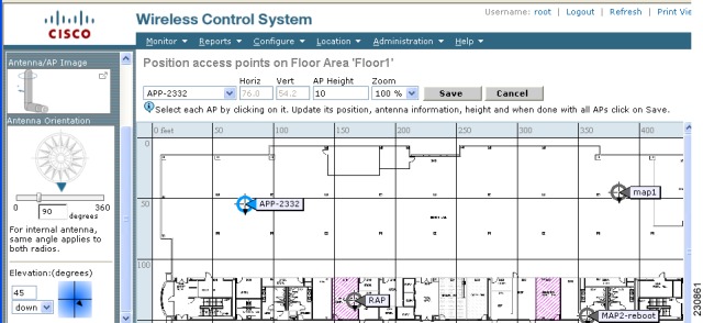
Step 1 Click the desired floor plan or outdoor area map in the Coverage Areas component of the General tab. Cisco Prime Infrastructure displays the associated coverage area map. Step 2 From the Select a command drop-down list, choose Add Access Points and click GO. Step 3 On the Add Access Points page, choose the mesh access points to add to the map. Step 4 Click OK to add the mesh access points to the map and display the Position Access Points map.
Note The mesh access point icons appear in the upper left area of the map.
Step 5 Click and drag the icons to indicate their physical locations. Step 6 Click each icon and choose the antenna orientation in the sidebar. The antenna angle is relative to the map’s X axis. Because the origin of the X (horizontal) and Y (vertical) axes is in the upper left corner of the map, 0 degrees points side A of the mesh access point to the right, 90 degrees points side A down, 180 degrees points side A to the left, and so on. The antenna elevation is used to move the antenna vertically, up or down, to a maximum of 90 degrees.
Make sure each mesh access point is in the correct location on the map and has the correct antenna orientation. Accurate mesh access point positioning is critical when you use the maps to find coverage holes and rogue access points.
See this location for further information about the antenna elevation and azimuth patterns:
http://www.cisco.com/en/US/products/hw/wireless/ps469/tsd_products_support_series_home.html
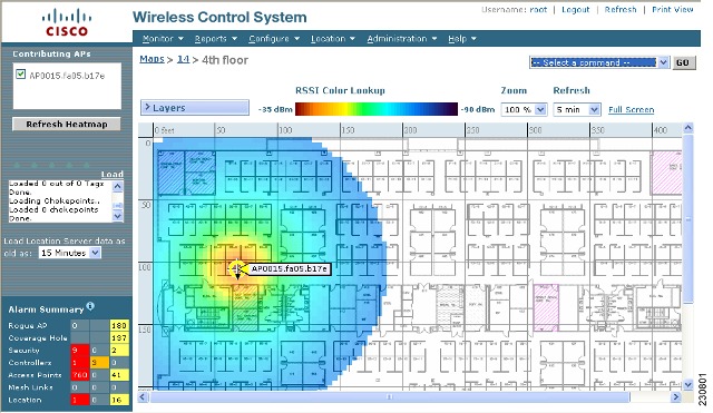
Step 7 Click Save to store the mesh access point locations and orientations. Cisco Prime Infrastructure computes the RF prediction for the coverage area. These RF predictions are popularly known as heat maps because they show the relative intensity of the RF signals on the coverage area map.
Note This display is only an approximation of the actual RF signal intensity because it does not take into account the attenuation of various building materials, such as drywall or metal objects. It also does not display the effects of RF signals bouncing off obstructions.
Monitoring Mesh Access Points Using Google Earth
Cisco Prime Infrastructure supports both Google Earth Map Plus or Pro and displays, when present, mesh access points and their links.
Launching Google Earth in Cisco Prime Infrastructure
Cisco Prime Infrastructure supports both Google Earth Map Plus or Pro and displays, when present, mesh access points and their links.
Step 1 Launch Google Earth plus or pro and add a new folder. Step 2 Create a mesh access points placemark on Google Earth plus or pro.
Note You must use the exact name of the mesh access point when creating the placement mark to ensure Prime Infrastructure can recognize these mesh access points.
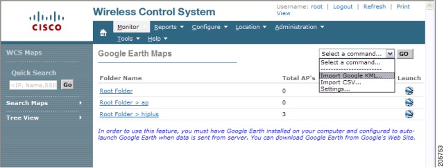
Step 3 Place the mesh access point placemarks in the new folder. Save the folder as a .KML file. Step 4 In the Prime Infrastructure, choose Monitor > Google Earth Maps. Select Import Google KML from the Select a command drop-down list. Step 5 Import the new Google KML folder. It displays in the folder name summary. Step 6 Click the launch icon next to the new folder to launch the Google Earth map from the Prime Infrastructure.
Viewing Google Earth Maps
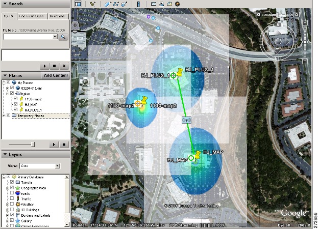
Step 1 Log on to Cisco Prime Infrastructure. Step 2 Choose Monitor > Google Earth Maps. The Google Earth Maps page displays all folders and the number of mesh access points included within each folder. Step 3 Click Launch for the map you want to view. Google Earth opens in a separate window and displays the location and its mesh access points.
Note To use this feature, you must have Google Earth installed on your computer and configured to auto-launch when data is sent from the server. You can download Google Earth from Google’s website.
Step 4 Click Launch for the map you want to view. Google Earth opens in a separate window and displays the location and its mesh access points.
Note To use this feature, you must have Google Earth installed on your computer and configured to auto-launch when data is sent from the server. You can download Google Earth from Google’s website.
To view details for a Google Earth Map folder, follow these steps:
Step 5 From the Google Earth Map page, click the folder name to open the details page for this folder. The Google Earth Details page provides the mesh access point names and MAC or IP addresses.
Note To delete a mesh access point, select the applicable check box and click Delete.?To delete the entire folder, select the check box next to Folder Name and click Delete. Deleting a folder also deletes all subfolders and mesh access points inside the folder.
Step 6 Click Cancel to close the details page.
Adding Indoor Mesh Access Points to Cisco Prime Infrastructure
You have a choice of ordering indoor access points directly into the bridge mode, so that these access points can be used directly as mesh access points. If you have these access points in a local mode (nonmesh), then you have to connect these access points to the controller and change the radio role to the bridge mode (mesh). This task can become cumbersome particularly if the volume of the access points being deployed is large and if the access points are already deployed in the local mode for a traditional nonmesh wireless coverage.
For local mode indoor access points prior to a mesh installation, you must first connect all indoor mesh access points to the controller and change the mode to bridge mode.
To do so, connect all the indoor access points to the Layer 3 network on the same subnet as the Management IP address.
Add the MAC address of the indoor mesh access points into the MAC filter list on the controller. All indoor access points will then join the controller in local mode.
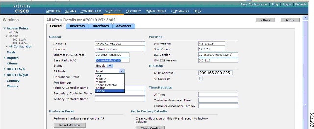
You can then change local mode to bridge mode in the controller for every indoor access point.
After changing the indoor access points to bridge mode on the controller, add these indoor mesh access points into the Prime Infrastructure.
You cannot initially configure indoor mesh access points into bridge mode from the Prime Infrastructure.
Managing Mesh Access Points with Cisco Prime Infrastructure
Cisco Prime Infrastructure is a complete platform for enterprise-wide WLAN systems management. It provides a wide range of tools for visualizing and controlling the mesh, including histograms of signal-to-noise ratio, mesh detail information, mesh access point neighbor and link information, seven-day temporal link information, and tools to identify and avoid RF interference.
This section addresses the following Prime Infrastructure monitoring capabilities:
- Monitoring Mesh Networks Using Maps
- Monitoring Mesh Health
- Viewing Mesh Statistics for a Mesh Access Point
- Viewing the Mesh Network Hierarchy
- Using Mesh Filters to Modify Map Display of Maps and Mesh Links
Monitoring Mesh Networks Using Maps
You can access and view details for the following elements from a mesh network map in the Cisco Prime Infrastructure.:
Details on how this information is accessed and the information displayed for each of these items is detailed in the following sections.
- Monitoring Mesh Link Statistics Using Maps
- Monitoring Mesh Access Points Using Maps
- Monitoring Mesh Access Point Neighbors Using Maps
Monitoring Mesh Link Statistics Using Maps
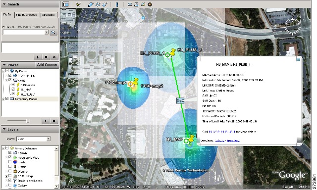
You can view the SNR for a specific mesh network link, view the number of packets transmitted and received on that link, and initiate a link test from the Monitor > Maps display.
To view details on a specific mesh link between two mesh access points or a mesh access point and a root access point, follow these steps:
Step 1 In Cisco Prime Infrastructure, choose Monitor > Maps. Step 2 Click the Map Name that corresponds to the outdoor area, campus, building, or floor you want to monitor. Step 3 Move the cursor over the link arrow for the target link. A Mesh Link page appears.
Note The AP Mesh Info check box under the Layers drop-down list must be selected for links to appear on the map.
Step 4 Click either Link Test, Child to Parent or Link Test, Parent to Child. After the link test is complete, a results page appears.
Note
Note You cannot run link tests for both links (child-to-parent and parent-to-child) at the same time.
Step 5 To view a graphical representation of SNR statistics over a period of time, click the arrow on the link. A page with multiple SNR graphs appears.
The following graphs are displayed for the link:
- SNR Up—Plots the RSSI values of the neighbor from the perspective of the mesh access point.
- SNR Down—Plots the RSSI values that the neighbor reports to the mesh access point.
- Link SNR—Plots a weighed and filtered measurement based on the SNR Up value.
- The Adjusted Link Metric —Plots the value used to determine the least cost path to the root mesh access point. This value is the ease to get to the rooftop access point and accounts for the number of hops. The lower the ease value, the less likely the path is used.
- The Unadjusted Link Metric —Plots the least cost path to get to the root access point unadjusted by the number of hops. The higher the value for the unadjusted link indicates the better the path.
Monitoring Mesh Access Points Using Maps
You can view the following summary information for a mesh access point from a mesh network map:
- Parent
- Number of children
- Hop count
- Role
- Group name
- Backhaul interface
- Data Rate
- Channel
NoteThis information is in addition to the information shown for all mesh access points (MAC address, mesh access point model, controller IP address, location, height of mesh access point, mesh access point up time, and CAPWAP up time).
To view summary and detailed configuration information for a mesh access point from a mesh network map, follow these steps:
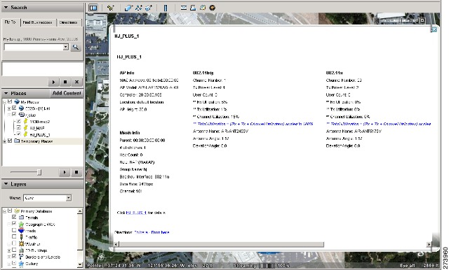
Step 1 On the GUI of Cisco Prime Infrastructure, choose Monitor > Maps. Step 2 Click the Map Name that corresponds to the outdoor area, campus, building, or floor location of the mesh access point you want to monitor. Step 3 To view summary configuration information for a mesh access point, move the cursor over the mesh access point that you want to monitor. A page with configuration information for the selected mesh access point appears. Step 4 To view detailed configuration information for a mesh access point, click the arrow portion of the mesh access point label. The configuration details for the mesh access point appears.
Note If the mesh access point has an IP address, a Run Ping Test link is also visible at the bottom of the mesh access point panel.
Step 5 On the Access Point configuration page, follow these steps to view configuration details for the mesh access point:
Monitoring Mesh Access Point Neighbors Using Maps
Step 1 Choose Monitor > Maps. Step 2 Click the Map Name that corresponds to the outdoor area, campus, building, or floor you want to monitor. Step 3 To view detailed information on mesh links for a mesh access point, click the arrow portion of the access point label. The Access Points screen appears. Step 4 Click the Mesh Links tab.
Note You can also mesh link details for neighbors of a selected mesh access point by clicking on the View Mesh Neighbors link on the mesh access point configuration summary panel that displays when you mouse over a mesh access point on a map.
Note Signal-to-noise ratio (SNR) only appears on the View Mesh Neighbors panel.
Note In addition to listing the current and past neighbors in the panel that displays, labels are added to the mesh access points map icons to identify the selected mesh access point, the neighbor mesh access point, and the child mesh access point. Select the clear link of the selected mesh access point to remove the relationship labels from the map.
Note The drop-down lists at the top of the mesh neighbors page indicate the resolution of the map (100%) displayed and how often the information displayed is updated (5 minutes). You can modify these default values.
Monitoring Mesh Health
Mesh Health monitors the overall health of outdoor and indoor mesh access points, except as noted. Tracking this environmental information is particularly critical for mesh access points that are deployed outdoors. The following factors are monitored:
- Temperature—Displays the internal temperature of the mesh access point in Fahrenheit and Celsius (AP1500s only).
- Heater status—Displays the heater as on or off (AP1500s only).
- AP Up time—Displays how long the mesh access point has been active to receive and transmit.
- CAPWAP Join Taken Time—Displays how long it took to establish the CAPWAP connection.
- CAPWAP Up Time—Displays how long the CAPWAP connection has been active.
Mesh Health information is displayed in the General Properties panel for mesh access points.
To view the mesh health details for a specific mesh access point, follow these steps:
Step 1 Choose Monitor > Access Points. A listing of access points appears.
Note You can also use the New Search button to display the mesh access point summary shown below. With the New Search option, you can further define the criteria of the access points that display. Search criteria include AP Type, AP Mode, Radio Type, and 802.11n Support.
Step 2 Click the AP Name link to display details for that mesh access point. The General Properties panel for that mesh access point appears.
NoteYou can also access the General properties panel for a mesh access point from a Cisco Prime Infrastructure map page. To display the panel, click the arrow portion of the mesh access point label. A tabbed panel appears and displays the General properties panel for the selected access point.
To add, remove, or reorder columns in the table, click the Edit View link. Table 1 displays optional access point parameters available from the Edit View page.
Table 1 Monitor Access Points Additional Search Results Parameters Indicates if antenna diversity is enabled or disabled. Antenna diversity refers to the access point sampling the radio signal from two integrated antenna ports in order to choose the preferred antenna.
Indicates the peak gain of the dBi of the antenna for directional antennas and the average gain in dBi for omnidirectional antennas connected to the wireless network adapter. The gain is in multiples of 0.5 dBm. An integer value 4 means 4 x 0.5 - 2 dBm of gain.
Indicates the antenna mode such as omni, directional, or nonapplicable.
Indicates the name of the bridge group used to group the access points, if applicable.
Indicates whether the channel control is automatic or custom.
Indicates the channel on which the Cisco radio is broadcasting.
Indicates the Power-over-Ethernet status of the access point. The possible values are as follows:
- Low—The access point draws low power from the Ethernet.
- Lower than 15.4 volts—The access point draws lower than ?15.4 V from the Ethernet.
- Lower than 16.8 volts—The access point draws lower than ?16.8 V from the Ethernet.
- Normal—The power is high enough for the operation of the access point.
- Not Applicable—The power source is not from the Ethernet.
Indicates the name of the primary controller for this access point.
Indicates whether or not the regulatory domain is supported.
Indicates whether the transmission power control is automatic or custom.
Indicates how long the access point has been up in days, hours, minutes, and seconds.
Indicates whether WLAN Override is enabled or disabled. Each access point is limited to 16 WLAN profiles. Each access point broadcasts all WLAN profiles unless the WLAN override feature is enabled. The WLAN override feature allows you to disable any of the 16 WLAN profiles per access point.
Viewing Mesh Statistics for a Mesh Access Point
Mesh Statistics are reported when a child mesh access point authenticates or associates with a parent mesh access point.
Security entries are removed and no longer displayed when the child mesh access point disassociates from the controller.
The following mesh security statistics are displayed for mesh access points:
To view the mesh statistics for a specific mesh access point, follow these steps:
Step 1 Choose Monitor > Access Points. A listing of access points appears.
Note You can also use the New Search button to display the access point summary. With the New Search option, you can further define the criteria of the access points that display. Search criteria include AP Name, IP address, MAC address, Controller IP or Name, Radio type, and Outdoor area.
Step 2 Click the AP Name link of the target mesh access point. A tabbed panel appears and displays the General Properties page for the selected mesh access point.
Step 3 Click the Mesh Statistics tab. A three-tabbed Mesh Statistics panel appears.
Note The Mesh Statistics tab and its subordinate tabs (Bridging, Queue and Security) only appear for mesh access points. The Mesh Link Alarms and Mesh Link Events links are accessible from each of the three tabbed panels.
Note You can also access the Mesh Securities panel for a mesh access point from a Cisco Prime Infrastructure map. To display the panel, click the arrow portion of the mesh access point label.
Summaries of the Bridging, Queue and Security Statistics and their definitions are provided in the following tables.
Table 2 Bridging Mesh Statistics The role of the mesh access point. Options are mesh access points (MAPs) and root access points (RAPs).
The name of the bridge group to which the MAP or RAP is a member. Assigning membership in a BGN is recommended. If one is not assigned, a MAP is by default assigned to a default BGN.
The state of parent selection. Values that display are seek, scan, and maint. Maint displays when parent selection is complete.
The number of malformed packets received from the neighbor. Examples of malformed packets include malicious floods of traffic such as malformed or short DNS packets and malformed DNS replies.
The number of times the signal-to-noise ratio falls below 12 dB on the backhaul link.
The number of packets received from excluded neighbor mesh access points.
The number of broadcast and unicast requests received from the neighbor mesh access points.
The number of responses received from the neighbor mesh access points.
The number of unicast and broadcast requests sent to the neighbor mesh access points.
The number of times a mesh access point (child) moves to another parent.
The number of hops between the MAP and the RAP. Click the value link to display a subpanel that enables you to configure details of what is reported, how often the node hop value is updated, and view a graphical representation of the report.
Table 3 Queue Mesh Statistics The average and peak number of packets waiting in the silver (best effort) queue during the defined statistics time interval. Packets dropped and queue size are also summarized.
The average and peak number of packets waiting in the gold (video) queue during the defined statistics time interval. Packets dropped and queue size are also summarized.
The average and peak number of packets waiting in the platinum (voice) queue during the defined statistics time interval. Packets dropped and queue size are also summarized.
The average and peak number of packets waiting in the bronze (background) queue during the defined statistics time interval. Packets dropped and queue size are also summarized.
The average and peak number of packets waiting in the management queue during the defined statistics time interval. Packets dropped and queue size are also summarized.
Table 4 Security Mesh Statistics Summarizes the total number of association request failures that occur between the selected mesh access point and its parent.
Summarizes the total number of successful association requests that occur between the selected mesh access point and its parent.
Summarizes the total number of association request time outs that occur between the selected mesh access point and its parent.
Summarizes the total number of failed authentication requests that occur between the selected mesh access point and its parent.
Summarizes the total number of successful authentication requests between the selected mesh access point and its parent mesh node.
Summarizes the total number of authentication request timeouts that occur between the selected mesh access point and its parent.
Summarizes the total number of invalid association requests received by the parent mesh access point from the selected child mesh access point. This state might occur when the selected child is a valid neighbor but is not in a state that allows association.
Summarizes the total number of invalid reassociation requests received by the parent mesh access point from a child. This state might occur when a child is a valid neighbor but is not in a proper state for reassociation.
Summarizes the total number of invalid reauthentication requests received by the parent mesh access point from a child. This state might occur when a child is a valid neighbor but is not in a proper state for reauthentication.
Summarizes the total number of packets received during security negotiations by the selected mesh access point.
Summarizes the total number of packets transmitted during security negotiations by the selected mesh access point.
Summarizes the total number of failed reassociation requests between the selected mesh access point and its parent.
Summarizes the total number of successful reassociation requests between the selected mesh access point and its parent.
Summarizes the total number of reassociation request timeouts between the selected mesh access point and its parent.
Summarizes the total number of failed reauthentication requests between the selected mesh access point and its parent.
Summarizes the total number of successful reauthentication requests that occurred between the selected mesh access point and its parent.
Summarizes the total number of reauthentication request timeouts that occurred between the selected mesh access point and its parent.
Summarizes the total number of unknown association requests received by the parent mesh access point from its child. The unknown association requests often occur when a child is an unknown neighbor mesh access point.
Summarizes the total number of unknown reassociation requests received by the parent mesh access point from a child. This state might occur when a child mesh access point is an unknown neighbor.
Summarizes the total number of unknown reauthentication requests received by the parent mesh access point node from its child. This state might occur when a child mesh access point is an unknown neighbor.
Viewing the Mesh Network Hierarchy
You can view the parent-child relationship of mesh access points within a mesh network in an easily navigable display. You can also filter which mesh access points display on the Map view, by selecting only mesh access points of interest.
To view the mesh network hierarchy for a selected network, follow these steps:
Step 1 Choose Monitor > Maps. Step 2 Select the map that you want to be displayed. Step 3 Click the Layers arrow to expand that menu. Step 4 Select the AP Mesh Info check box if it is not already checked.
Note The AP Mesh Info check box can be selected only if mesh access points are present on the map. It must be checked to view the mesh hierarchy.
Step 5 Click the AP Mesh Info arrow to display the mesh parent-child hierarchy. Step 6 Click the plus (+) sign next to a mesh access point to display its children. All subordinate mesh access points are displayed when a negative (-) sign displays next to the parent mesh access point entry.
Step 7 Move the cursor over the colored dot next to each mesh access point child to view details on the link between it and its parent. Table 1 summarizes the parameters that display. The color of the dot also provides a quick reference point of the SNR strength.
Using Mesh Filters to Modify Map Display of Maps and Mesh Links
In the mesh hierarchical page, you can also define mesh filters to determine which mesh access points display on the map based on hop values as well as what labels display for mesh links.
Mesh access points are filtered by the number of hops between them and their root access point.
Step 1 To modify what label and color displays for a mesh link, do the following: In the Mesh Parent-Child Hierarchical View, select an option from the Link Label drop-down list. Options are None, Link SNR, and Packet Error Rate.
In the Mesh Parent-Child Hierarchical View, select an option from the Link Color drop-down list to define which parameter (Link SNR or Packet Error Rate) determines the color of the mesh link on the map.
Note The color of the link provides a quick reference point of the SNR strength or Packet Error Rate.
Table 6 Definition for SNR and Packet Error Rate Link Color Represents a PER that is less than ten percent (10%) and greater than one percent (1%)
Note The Link label and color settings are reflected on the map immediately. You can display both SNR and PER values simultaneously.
Step 2 To modify which mesh access points display based on the number of hops between them and their parents, do the following: In the Mesh Parent-Child Hierarchical View, click the Quick Selections drop-down list.
Select the appropriate option from the list.
Table 7 Quick Selection Options Choose this setting if you want the map view to display root access points only.
Choose this setting if you want the map view to display 1st hops only.
Choose this setting if you want the map view to display 2nd hops only.
Choose this setting if you want the map view to display 3rd hops only.
Choose this setting if you want the map view to display 4th hops only.
Select this setting if you want the map view to display all access points.
Click Update Map View to refresh the screen and redisplay the map view with the selected options.
Note Map view information is retrieved from the Cisco Prime Infrastructure database and is updated every 15 minutes.
Note You can also select or deselect the check boxes of mesh access points in the mesh hierarchical view to modify which mesh access points are displayed. For a child access point to be visible, the parent access point to root access point must be selected.
Monitoring Workgroup Bridges
Multiple VLAN and QoS Support for WGB Wired Clients
A WGB is a small standalone unit that can provide a wireless infrastructure connection for Ethernet-enabled devices. Devices that do not have a wireless client adapter to connect to the wireless network can be connected to the WGB through the Ethernet port. The WGB associates with the root AP through the wireless interface, which means that wired clients get access to the wireless network.
This feature provides the segregation of traffic based on VLANs for different applications running on different devices connected to a switch behind a WGB. Traffic from WGB clients are sent in the right priority queue in the mesh backhaul based on DSCP/dot1p values.
NoteYou need a special autonomous image on the autonomous access points being used as a WGB for interoperability with the Unified CAPWAP infrastructure. This image will be merged with the next official autonomous release.
The WGB informs the WLC about the wired-client VLAN information in an IAPP association message. The WGB removes the 802.1Q header from the packet while sending to the WLC. The WLC sends the packet to the WGB without the 802.1Q tag and the WGB adds 802.1Q header to packets that go to the wired switch based on the destination MAC address.
The WLC treats the WGB client as a VLAN client and forwards the packet in the right VLAN interface based on the source MAC address.
You must enable the WGB unified client for multiple VLAN support on the WGB by entering the workgroup-bridge unified-VLAN-client command. This WGB unified client is disabled by default.
You have to configure subinterfaces on the WGB that corresponds to the VLANs on the switch ports to which the wired clients are connected.
- Workgroup Bridge Guidelines
- Configuring VLAN and QoS Support (CLI)
- Workgroup Bridge Output
- WGB Detail on Controller
- Troubleshooting Tips
Workgroup Bridge Guidelines
Follow these guidelines when configuring WGBs:
- A dynamic interface should be created in the controller for each VLAN that is configured in the WGB.
- Only one WLAN (SSID) for a wireless association of the WGB to the access point infrastructure is supported. This SSID should be configured as an infrastructure SSID and should be mapped to the native VLAN. The WGB drops everything that is not in the native VLAN in the mesh infrastructure.
- We recommend that you configure the same native VLAN in the switch that connects the WLC, WGB, and in the switch behind the WGB. All native VLAN clients on the WGB Ethernet side are part of the same VLAN in which the WGB is associated. The WGB is part of the VLAN to which the WLAN (in which the WGB has associated) is mapped. For example, if in the WGB, the 5-GHz radio (dot11radio 1) is mapped to a native VLAN 184, and the switch behind WGB has wired clients only in VLAN 185 and 186, then you may not require the native VLAN to be identical to the native VLAN on the WGB (VLAN 184). But, if you add one wired client in VLAN 184 and this VLAN client in the WGB belongs to a native VLAN, you must define the same native VLAN on the switch.
- Intersubnet mobility is supported with this feature for VLAN clients behind the WGB with a limitation that the dynamic interface for all VLANs of the WGB should be configured in all the controllers.
- Interoperability with a VLAN-pooling feature is not supported. When the VLAN-pooling feature is enabled, the WGB and its native VLAN clients become part of the same VLAN.
- AAA-override for WGB clients is not supported, but AAA-override for the WGB is supported.
- Only Layer 3 multicast is provided for WGB VLAN clients and there is no support for Layer 2 multicast.
- There is a 20-client limitation in WGB that includes wireless clients.
- Link testing for WGB wired clients is not supported.
- Roaming is supported for wireless and wired clients behind WGB.
- Multicast is supported for wired clients behind WGB.
- Broadcast is supported.
- Non-Cisco workgroup bridges are supported on Mesh access points.
Configuring VLAN and QoS Support (CLI)
In the following example, VLANs 184 and 185 exist on the wired switch behind WGB. WGB’s native VLAN is 184. SSID is auto-wgb mapped to native VLAN 184. Radio 1 (5 GHz) radio is used to connect to the CAPWAP infrastructure using this SSID.
ap#config t
ap(config)#workgroup-bridge unified-VLAN-client
ap(config)#int FastEthernet0.184
ap(config-subif)#encapsulation dot1q 184 native
ap(config-subif)#bridge-group 1
ap(config-subif)#exit
ap(config)#int FastEthernet0.185
ap(config-subif)#encapsulation dot1q 185
ap(config-subif)#bridge-group 185
ap(config-subif)#exit
ap(config)#int Dot11Radio 1.185
ap(config-subif)#encapsulation dot1q 185
ap(config-subif)#bridge-group 185
ap(config-subif)#exit
ap(config)#int Dot11Radio 1.184
ap(config-subif)#encapsulation dot1q 184 native
ap(config-subif)#bridge-group 1
ap(config-subif)#exit
ap(config)#dot11 ssid auto-wgb
ap(config-ssid)#authentication open
ap(config-ssid)#infrastructure-ssid
ap(config-ssid)#VLAN 184
ap(config-ssid)#exit
ap(config)#int Dot11Radio 1
ap(config-if)#station-role workgroup-bridge
ap(config-if)#ssid auto-wgb
ap(config-if)#exit
ap(config)#bridge irb
ap(config)#hostname WGB
The bridge irb command is used to enable integrated routing and bridging, which the Auto AP code has retained from other higher end platforms.
You have to create dynamic interfaces 184 and 185 on the WLC for the above configuration to work. The WGB updates the WLC about the wired-client VLAN information in the IAPP association message. The WLC treats the WGB client as a VLAN-client and forwards the packet in the right VLAN interface based on the source MAC address. In the upstream direction, the WGB removes the 802.1Q header from the packet and sends it to the WLC. In the downstream direction, the WLC sends the packet to the WGB without the 802.1Q tag and the WGB adds the 802.1Q header based on the destination MAC address, while forwarding the packet to the switch that connects the wired client.
Workgroup Bridge Output
WGB#sh bridge
Total of 300 station blocks, 292 free
Codes: P - permanent, S - self

Bridge Group 1:
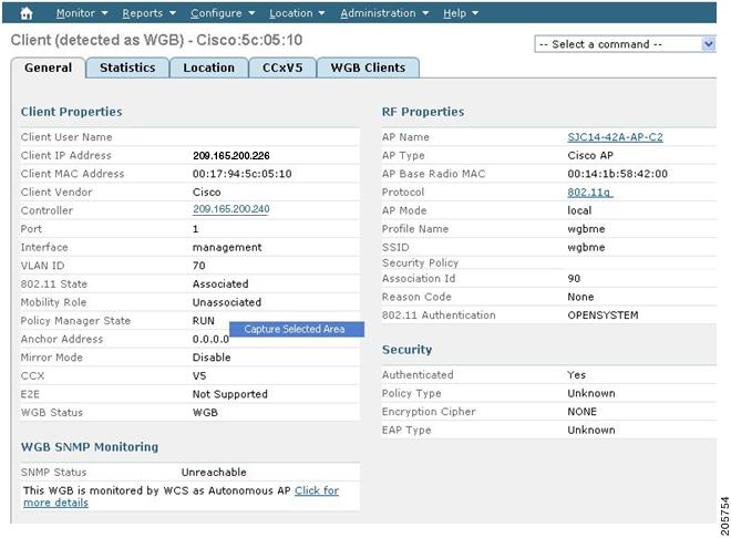
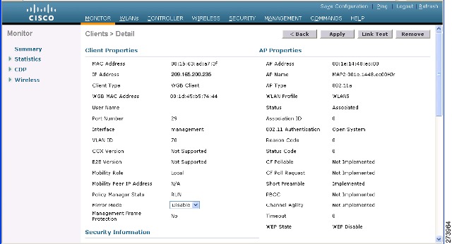
WGB Detail on Controller
To display WGB details about the controller, enter the following command:
(Cisco Controller) > show wgb summary
Number of WGBs................................... 2
Troubleshooting Tips
If a WGB client does not associate with the WGB, note these tips to troubleshoot the problem:
- The native VLAN that is configured on the WGB needs to be the same VLAN on the switch to which the WGB is connected. The switch port connected to the WGB should be Trunk.
- Verify the client configuration and ensure that the client configuration is correct.
- Check the show bridge command output in the autonomous AP and confirm that the AP is reading the client MAC address in the right interface.
- Confirm that the subinterfaces that correspond to specific VLANs and different subinterfaces are mapped to the bridge group.
- WGB reads the switch port behind as a client in its MAC address table.
- If required, clear the bridge entry using the clear bridge command (remember that this command will remove all the wired and wireless clients associated with the WGB and make them associated again).
- Ensure that the WGB has not exceeded its 20-client limitation.
Viewing AP Last Reboot Reason
Cisco Prime Infrastructure reports the reason for the most recent reboot on the general panel of the access point details page (Monitor > Access Points > AP Name).
Listed below is a summary of each of the possible Last Reboot Reasons that might be reported and its definition:
- none–Access point reported a reboot reason unknown to the controller
- dot11gModeChange–Change of 802.11g mode change occurred
- ipAddressSet–Set of static IP address
- ip AddressReset–Reset of static IP address
- rebootFromController–Reboot of access point initiated from the controller
- dhcpFallbackFail–Fallback to DHCP did not occur
- discoveryFail–Discovery was not sent
- noJoinResponse–Join response was not received
- denyJoin–Join attempt at the controller was denied
- noConfigResponse–Config Response was not received
- configController–Configured or master controller found
- imageUpgrade Success–Upgrade of image successful
- imageOpcodeInvalid–Invalid image data opcode
- imageCheckSumInvalid–Invalid image md 5 checksum
- imageDataTimeout–Image data message timed-out
- configFileInvalid–Invalid config file
- imageDownloadError–Process error during the image download
- rebootFromConsole–Reboot command initiated from AP console
- rapOverAir–Root access point (RAP) is connected over the air
- brownout–Power failure caused reboot
- powerLow–Low power caused a reboot
- crash–Software failure caused crash
- powerHigh–Power spike caused reboot
- powerLoss–Power loss caused reboot
- powerCharge–Change in power source caused reboot
- componentFailure–Component failure caused reboot
- watchdog–Watch dog timer reset caused reboot