Feedback
Contents
- Mesh Network Components
- Mesh Access Points
- Licensing for Mesh Access Points on a 5500 Series Controller
- Access Point Roles
- Network Access
- Network Segmentation
- Cisco Indoor Mesh Access Points
- Cisco Outdoor Mesh Access Points
- Cisco Aironet 1552 Mesh Access Point
- Cisco 1522 Mesh Access Point
- Cisco 1524PS Mesh Access Point
- Cisco 1524SB Mesh Access Point
- Ethernet Ports
- Multiple Power Options
- Battery Backup Module (Optional)
- Reset Button
- Resetting Access Point
- Monitoring the LED Status
- Serial Backhaul Access Point Guidelines for the Rest of the World (ROW)
- Discontinuation of the 116 and 132 Channels from the UNII-2 Extended Band
- Frequency Bands
- Dynamic Frequency Selection
- Antennas
- Antenna Configurations for 1552
- Client Access Certified Antennas (Third-Party Antennas)
- Maximum Ratio Combining
- Cisco 1500 Hazardous Location Certification
- Cisco Wireless LAN Controllers
- Cisco Prime Infrastructure
- Architecture
- Control and Provisioning of Wireless Access Points
- CAPWAP Discovery on a Mesh Network
- Dynamic MTU Detection
- XML Configuration File
- Adaptive Wireless Path Protocol
- Traffic Flow
- Mesh Neighbors, Parents, and Children
- Criteria to Choose the Best Parent
- Ease Calculation
- Parent Decision
- SNR Smoothing
- Loop Prevention
Mesh Network Components
This chapter describes the mesh network components.
The Cisco wireless mesh network has four core components:
- Cisco Aironet 1500 series mesh access points
NoteCisco Aironet 1505 and 1510 mesh access points are not supported because of their End-of-Life status.
- Cisco Wireless LAN Controller (hereafter referred to as controller)
- Cisco Prime Infrastructure
- Mesh software architecture
This chapter contains the following sections:
Mesh Access Points
- Licensing for Mesh Access Points on a 5500 Series Controller
- Access Point Roles
- Network Access
- Network Segmentation
- Cisco Indoor Mesh Access Points
- Cisco Outdoor Mesh Access Points
Licensing for Mesh Access Points on a 5500 Series Controller
To use both mesh and nonmesh access points with a Cisco 5500 Series Controller, only the base license (LIC-CT5508-X) is required from the 7.0 release and later releases. For more information about obtaining and installing licenses, see the Cisco Wireless LAN Controller Configuration Guide at http://www.cisco.com/en/US/products/ps10315/products_installation_and_configuration_guides_list.html.
Access Point Roles
Access points within a mesh network operate in one of the following two ways:
- Root access point (RAP)
- Mesh access point (MAP)
While the RAPs have wired connections to their controller, the MAPs have wireless connections to their controller.
MAPs communicate among themselves and back to the RAP using wireless connections over the 802.11a/n radio backhaul. MAPs use the Cisco Adaptive Wireless Path Protocol (AWPP) to determine the best path through the other mesh access points to the controller.
Bridge mode access points support CleanAir in mesh backhaul at 5GHz frequency and provides only the interference device report (IDR) and Air Quality Index (AQI)reports.
NoteThe RAP or MAP does not generate Bridge Protocol Data Unit (BPDU) itself. However, the RAP or MAP forwards the BPDU to upstream devices if the RAP or MAP received the BPDU from its connected wired or wireless interface across the network.
Network Access
Wireless mesh networks can simultaneously carry two different traffic types. They are as follows:
Wireless LAN client traffic terminates on the controller, and the Ethernet traffic terminates on the Ethernet ports of the mesh access points.
Access to the wireless LAN mesh for mesh access points is managed by the following authentication methods:
- MAC authentication—Mesh access points are added to a database that can be referenced to ensure they are provided access to a given controller and mesh network.
- External RADIUS Authentication—Mesh access points can be externally authorized using a RADIUS server such as Cisco ACS (4.1 and later) that supports the client authentication type of Extensible Authentication Protocol-FAST (EAP-FAST) with certificates.
Cisco Indoor Mesh Access Points
NoteFor more information about controller software support for access points, see the Cisco Wireless Solutions Software Compatibility Matrix at http://www.cisco.com/en/US/docs/wireless/controller/5500/tech_notes/Wireless_Software_Compatibility_Matrix.html.
Enterprise 11n mesh is an enhancement added to the CUWN feature to work with the 802.11n access points. Enterprise 11n mesh features are compatible with non-802.11n mesh but adds higher backhaul and client access speeds. The 802.11n indoor access points are two-radio Wi-Fi infrastructure devices for select indoor deployments. One radio can be used for local (client) access for the access point and the other radio can be configured for wireless backhaul. The backhaul is supported only on the 5-GHz radio. Enterprise 11n mesh supports P2P, P2MP, and mesh types of architectures.
You have a choice of ordering indoor access points directly into the bridge mode, so that these access points can be used directly as mesh access points. If you have these access points in a local mode (nonmesh), then you have to connect these access points to the controller and change the AP mode to the bridge mode (mesh). This scenario can become cumbersome particularly if the volume of the access points being deployed is large and if the access points are already deployed in the local mode for a traditional nonmesh wireless coverage.
The Cisco indoor mesh access points are equipped with the following two simultaneously operating radios:
The 5-GHz radio supports the 5.15 GHz, 5.25 GHz, 5.47 GHz, and 5.8 GHz bands.
Cisco Outdoor Mesh Access Points
Cisco outdoor mesh access points comprise of the Cisco Aironet 1500 series access points. The 1500 series includes 1552 11n outdoor mesh access points, 1522 dual-radio mesh access points, and 1524 multi-radio mesh access points. There are two models of the 1524, which are the following:
- The public safety model, 1524PS
- The serial backhaul model, 1524SB
Note
In the 6.0 release, the AP1524SB access point was launched in A, C, and N domains. In the 7.0 release, the AP1524SB access point was launched in the -E, -M, -K, -S, and -T domains.
Cisco 1500 series mesh access points are the core components of the wireless mesh deployment. AP1500s are configured by both the controller (GUI and CLI) and Cisco Prime Infrastructure. Communication between outdoor mesh access points (MAPs and RAPs) is over the 802.11a/n radio backhaul. Client traffic is generally transmitted over the 802.11b/g/n radio (802.11a/n can also be configured to accept client traffic), and public safety traffic (AP1524PS only) is transmitted over the 4.9-GHz radio.
The mesh access point can also operate as a relay node for other access points not directly connected to a wired network. Intelligent wireless routing is provided by the Adaptive Wireless Path Protocol (AWPP). This Cisco protocol enables each mesh access point to identify its neighbors and intelligently choose the optimal path to the wired network by calculating the cost of each path in terms9 of the signal strength and the number of hops required to get to a controller.
AP1500s are manufactured in two different configurations: cable and noncable.
- The cable configuration can be mounted to a cable strand and supports power-over-cable (POC).
- The noncable configuration supports multiple antennas. It can be mounted to a pole or building wall and supports several power options.
Uplinks support includes Gigabit Ethernet (1000BASE-T) and a small form-factor (SFP) slot that can be plugged for a fiber or cable modem interface. Both single mode and multimode SFPs up to 1000BASE-BX are supported. The cable modem can be DOCSIS 2.0 or DOCSIS/EuroDOCSIS 3.0 depending upon the type of mesh access point.
AP1500s are available in a hazardous location hardware enclosure. When configured, the AP1500 complies with safety standards for Class I, Division 2, Zone 2 hazardous locations.
Note
See the Cisco Aironet 1520 Series Lightweight Outdoor Access Point Ordering Guide for power, mounting, antenna, and regulatory support by model: http://www.cisco.com/en/US/prod/collateral/wireless/ps5679/ps8368/product_data_sheet0900aecd8066a157.html
The mesh access points, can operate, apart from the mesh mode, in the following modes:
- Local mode—In this mode, the AP can handle clients on its assigned channel or while monitoring all channels on the band over a 180-second period. During this time, the AP listens on each channel for 50 milliseconds for rogue client beacons, noise floor measurements, interference, and IDS events. The AP also scans for CleanAir interference on the channel.
- FlexConnect mode—FlexConnect is a wireless solution for branch office and remote office deployments. The FlexConnect mode enables you to configure and control access points in a branch or remote office from the corporate office through a WAN link without having to deploy a controller in each office. The FlexConnect mode can switch client data traffic locally and perform client authentication locally when the connection to the controller is lost. When connected to the controller, the FlexConnect mode can also tunnel traffic back to the controller.
- Monitor mode—In this mode, the AP radios are in the receive state. The AP scans all the channels every 12 seconds for rogue client beacons, noise floor measurements, interference, IDS events, and CleanAir intruders.
- Rogue Detector mode—In this mode, the AP radio is turned off, and the AP listens only to the wired traffic. The controller passes the APs that are configured as rogue detectors as well as lists of suspected rogue clients and AP MAC addresses. The rogue detector listens for ARP packets and can be connected to all broadcast domains through a trunk link.
- Sniffer mode—In this mode, the AP captures and forwards all packets on a channel to a remote device that decodes the packets with packet analyzer software such as Wireshark.
Note
You can configure these modes using both the GUI and CLI. For configuration instructions, see the Cisco Wireless LAN Controller Configuration Guide.
Note
MAPs can only be configured in Bridge mode regardless of their wired or wireless backhaul. If the MAPs have a wired backhaul, you must change their AP role to RAP before you change the AP Mode.
- Cisco Aironet 1552 Mesh Access Point
- Cisco 1522 Mesh Access Point
- Cisco 1524PS Mesh Access Point
- Cisco 1524SB Mesh Access Point
- Ethernet Ports
- Multiple Power Options
- Battery Backup Module (Optional)
- Reset Button
- Resetting Access Point
- Monitoring the LED Status
- Serial Backhaul Access Point Guidelines for the Rest of the World (ROW)
- Discontinuation of the 116 and 132 Channels from the UNII-2 Extended Band
- Frequency Bands
- Dynamic Frequency Selection
- Antennas
- Antenna Configurations for 1552
- Client Access Certified Antennas (Third-Party Antennas)
- Maximum Ratio Combining
- Cisco 1500 Hazardous Location Certification
Cisco Aironet 1552 Mesh Access Point
The Cisco Aironet 1550 Series Outdoor Mesh Access Point is a modularized wireless outdoor 802.11n access point designed for use in a mesh network. The access point supports point-to-multipoint mesh wireless connectivity and wireless client access simultaneously. The access point can also operate as a relay node for other access points that are not directly connected to a wired network. Intelligent wireless routing is provided by the Adaptive Wireless Path Protocol (AWPP). This enables the access point to identify its neighbors and intelligently choose the optimal path to the wired network by calculating the cost of each path in terms of signal strength and the number of hops required to get to a controller.
The 1550 series access points leverage 802.11n technology with integrated radio and internal/external antennas. The 1552 outdoor platform consists of Multiple Input Multiple Output (MIMO) WLAN radios. It offers 2x3 MIMO with two spatial streams, Beamforming, and comes with integrated spectrum intelligence (CleanAir).
CleanAir provides full 11n data rates while detecting, locating, classifying, and mitigating radio frequency (RF) interference to provide the best client experience possible. CleanAir technology on the outdoor 11n platform mitigates Wi-Fi and non-Wi-Fi interference on 2.4-GHz radios.
The 1550 series access points have two radios—2.4-GHz and 5-GHz MIMO radios. While the 2.4-GHz radios are used primarily for local access, the 5-GHz radios are used for both local access and wireless backhaul in mesh mode.
Note
The wIPS submode is not supported on the Cisco 1552 Series Mesh Access Points.
Note
The 2.4-GHz radios cannot be used for backhaul in 1552 APs.
The 2-GHz b/g/n radio has the following features:
- Operates in the 2.4-GHz ISM band.
- Supports channels 1-11 in the United States, 1-13 in Europe, and 1-13 in Japan.
- Has two transmitters for 802.11b/g/n operation.
- You can configure the output power for 5 power levels.
- The radio has three receivers that enable maximum-ratio combining (MRC).
The 5-GHz a/n radio has the following feature:
- Operates in the UNII-2 band (5.25 to 5.35 GHz), UNII-2 Extended/ETSI band (5.47 to 5.725 GHz), and the upper ISM band (5.725 to 5.850 GHz).
- Has two transmitters for 802.11a operation.
- Power settings can change depending on the regulatory domain. You can configure the output power for 5 power levels in 3 dB steps.
- The radio has three receivers that enable maximum-ratio combining (MRC).
The 1550 series access points have the following features:
- Supports modularity of the 1520 series and allows flexibility in radio configuration
- Fully interoperable with the 1520 series access points
- Can also interoperate with legacy clients and offers enhanced backhaul performance
- Multicast VideoStream and HotSpot 2.0 are supported when the AP is configured in Local mode.
- AP1552 is QoS capable of supporting quality VoWLAN calls.
- Band Select, which notifies a connected client to roam from 2.4 GHz to 5 GHz, is supported.
- DTLS support allows AP1552 to encrypt data in all supported AP modes except Bridge mode.
- You can enable CleanAir on the 5-GHz radio by navigating to Wireless > Radios > 802.11a > Configure on the controller GUI.
- If AP1552 is in Bridge mode, CleanAir Advisor becomes operational. CleanAir Advisor generates CleanAir reports and identifies interference. The event driven RRM is disabled. Therefore, the radio does not change the transmission power level or channel.
The models can be classified as models with external antennas and models with built-in antennas. The 1552C model is configured with an integrated DOCSIS/EuroDOCSIS 3.0 cable modem. The DOCSIS 3.0 cable modem provides 8 DS and 4 US (8x4), 304x108 Mbps. The EuroDOCSIS 3.0 cable modem provides 4 US and 4 DS (4x4), 152x108 Mbps. While a DOCSIS 2.0 cable modem could provide throughput of up to 40 Mbps only, a DOCSIS 3.0 cable modem can provide a DS throughput of 290 Mbps and a US throughput of 100 Mbps.
For more information about the Cisco 1550 Series Access Points, see http://www.cisco.com/en/US/products/ps11451/index.html.
1552E
The Cisco Aironet 1552E Outdoor Access Point is the standard model, dual-radio system with dual-band radios that are compliant with IEEE 802.11a/n (5-GHz) and 802.11b/g/n standards (2.4 GHz). The 1552E has three external antenna connections for three dual-band antennas. It has Ethernet and fiber Small Form Factor Pluggable (SFP) backhaul options, along with the option of a battery backup. This model also has a PoE-out port and can power a video surveillance camera. A highly flexible model, the Cisco Aironet 1552E is well equipped for municipal and campus deployments, video surveillance applications, mining environments, and data offload.
The 1552E model has the following features:
- Weighs 17.3 lbs (7.9 kg) excluding external antennas
- Two radios (2.4 GHz and 5 GHz)
- Three external dual-band omnidirectional antennas with 4 dBi in 2.4 GHz and 7 dBi in 5 GHz
- Vertical beamwidth: 29° at 2.4 GHz, 15° at 5 GHz
- Aligned console port
- Higher equivalent isotropically radiated power (EIRP)
- Multiple uplinks with Ethernet and fiber
- An optional Small Form Factor Pluggable (SFP) fiber module that can be ordered with the AP. The AP can use SFP fiber or copper module.
- 802.3af-compliant PoE-Out option to connect IP devices (such as video cameras)
- AC Powered (100 to 480 VAC)
- PoE-In using Power Injector
- Battery backup option (6 AH)
Note
The 1552E model has no cable modem. The 1552E battery cannot be used for 1552H.
Note
The EPON SFP feature must be ordered separately and installed.
1552C
Where service providers have already invested in a broadband cable network, the Cisco next-generation outdoor wireless mesh can seamlessly extend network connectivity with the Cisco Aironet 1552C access point by connecting to its integrated cable modem interface. The Cisco Aironet 1552C Outdoor Mesh Access Point is a dual-radio system with DOCSIS 3.0/EuroDOCSIS 3.0 (8x4 HFC) cable modem for power and backhaul. It has dual-band radios that are compliant with IEEE 802.11a/n (5 GHz) and 802.11b/g/n standards (2.4 GHz). The 1552C has an integrated, three- element, dual-band antenna and easily fits within the 30 cm height restriction for service providers. This model is suitable for 3G data offload applications and public Wi-Fi.
The 1552C model has the following features:
- Lightweight (14 lbs or 6.4 kg), low-profile AP
- Two radios (2.4 GHz and 5 GHz)
- DOCSIS/EuroDOCSIS 3.0 Cable Modem
- Aligned console port
- It supports cable modem backhaul
- Has an integrated 3-element array antenna with 2 dBi in 2.4 GHz and 4 dBi in 5 GHz
- Input module, power-over-cable supply (40 to 90 VAC)
- Stamped cover with two convenient holes to tighten the seizure screw for stringer connector (RF/Power Input) and to adjust the fuse pad to attenuate the signal
Note
The 1552C model has no battery backup, no fiber SFP support, no PoE Out, no PoE In using Power Injector or Ethernet port, and no AC power option.
1552I
The Cisco Aironet 1552I Outdoor Access Point is a low-profile, lighter weight model. The smaller size and sleeker look helps it blend with the surrounding environment. The smaller power supply also makes it an energy efficient product. The 1552I does not have PoE-Out or a fiber SFP port.
1552H
This access point is designed for hazardous environments like oil and gas refineries, chemical plants, mining pits, and manufacturing factories. The Cisco Aironet 1552H Outdoor Access Point is Class 1, Div 2/Zone 2 hazardous location certified. The features are similar to the 1552E model, with the exception of the battery backup.
The 1552H model has the following features:
- Weighs 14 lbs (6.4 kg)
- Two radios (2.4 GHz and 5 GHz)
- Hazardous Location (Haz Loc) version.
- Power-over-Ethernet (PoE) input using Power Injector
- Aligned console port
- Three dual-band external omnidirectional antennas
- AC entry module with terminal block
- AC powered (100 to 240 VAC, as per ATEX certification requirement)
- Fiber SFP backhaul option
- 802.3af-compliant PoE Out option to connect IP devices (such as video cameras)
- Battery backup option (special battery for hazardous locations)
For more information about Cisco Aironet 1552 mesh access point hardware and installation instructions, see http://www.cisco.com/en/US/products/ps11451/prod_installation_guides_list.html
1552EU
The 1552EU model has the following features:
- Two radios (2.4 GHz and 5 GHz)
- Aligned console port
- AC powered (90 to 480 VAC)
- PoE 802.3af
- External high-gain antennas (13 dBi in 2.4 GHz, 14 dBi in 5 GHz)
- Battery
Note
The EPON SFP feature must be ordered separately and installed.
Cisco 1522 Mesh Access Point
The AP1522 mesh access point (part numbers: AIR–LAP1522AG–X–K9, AIR–LAP1522HZ–X–K9, AIR–LAP1522PC–X–K9) includes two radios: a 2.4-GHz and a 4.9- to 5.8-GHz radio. The 2.4-GHz (802.11b/g) radio is for client access and the 5-GHz (802.11a) radio is used as the backhaul. With the 7.0.116.0 release and later releases, 2.4 GHz is available for backhaul. This feature is applicable only to AP1522.
The 5-GHz radio is a 802.11a radio that covers the 4.9- to 5.8-GHz frequency band and is used as a backhaul. It can also be used for client access if the universal client access feature is enabled.
NoteAP1522s with serial numbers prior to FTX1150XXXX do not support 5- and 10-MHz channels on the 4.9-GHz radio; however, a 20-MHz channel is supported.
NoteThose AP1522s with serial numbers after FTX1150XXXX support 5-, 10-, and 20-MHz channels.
Cisco 1524PS Mesh Access Point
The AP1524PS mesh access point (part number: AIR–LAP1524PS–X–K9) includes three radios: a 2.4-GHz, a 5.8-GHz, and a 4.9-GHz radio. The 2.4-GHz radio is for client access (nonpublic safety traffic) and the 4.9-GHz radio is for public safety client access traffic only. The 5.8-GHz radio can be used as the backhaul for both public safety and nonpublic safety traffic.
The 4.9-GHz and 5.8-GHz radios are 802.11a subband radios that support a subset of specific 802.11a channels and include a subband specific filter designed to lessen interference from other 11a subband radios within the same mesh access point.
The 4.9-GHz subband radio on the AP1524 supports public safety channels within the 5-MHz (channels 1 to 10), 10-MHz (channels 11 to 19), and 20-MHz (channels 20 to 26) bandwidths.
Cisco 1524SB Mesh Access Point
The AP1524SB mesh access point (part number: AIR–LAP1524SB–X–K9) includes three radios: one 2.4-GHz radio and two 5-GHz radios.
The 2.4-GHz radio is for client access (nonpublic safety traffic). The two 5-GHz radios serve as serial backhauls: one uplink and one downlink. The AP1524SB is suitable for linear deployments.
NoteIn the 6.0 release, the 5-GHz radios in the –A domain could be operated only in the 5.8-GHz band with 5 channels. In the 7.0 release, these radios cover the whole 5-GHz band.
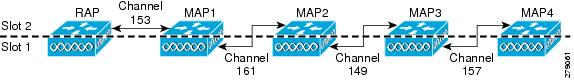
Each 5-GHz radio backhaul is configured with a different backhaul channel. There is no need to use the same shared wireless medium between the north-bound and south-bound traffic in a mesh tree-based network.
On the RAP, the radio in slot 2 is used to extend the backhaul in the downlink direction; the radio in slot 1 is used only for client access and not mesh.
On the MAP, the radio in slot 2 is used for the backhaul in the uplink direction; the radio in slot 1 is used for the backhaul in the downlink direction.
You only need to configure the RAP downlink (slot 2) channel. The MAPs automatically select their channels from the channel subset. The available channels for the 5.8-GHz band are 149, 153, 157, 161, and 165.
Figure 2. Channel Selection Example. This figure shows an example of channel selection when the RAP downlink channel is 153.Fall Back Mode
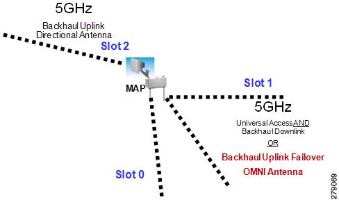
Slot 1 in a 5-GHz radio in a MAP can act as an uplink radio for the backhaul in any one of the following scenarios:
- Slot 2 radio fails.
- Antenna for slot 2 radio goes bad.
- Slot 2 radio is unable to find the uplink because of a bad RF design.
- Interference and long-term fades disturb the uplink to the extent that the slot 2 radio loses its uplink connection.
When a slot 1 radio takes over a slot 2 radio, it is called Fall Back Mode. The slot 2 radio is made inactive on a noninterfering channel. The hardware is reduced to AP1522 (two radios). The slot 1 radio (omni antenna) is extended to the uplink. A period of 15 minutes is set on a timer to attempt a rescan to find a parent on the slot 2 radio again. The timer is similar to the default BGN timer.
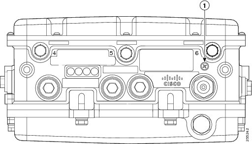
The antenna ports are labeled on the AP1524SB and are connected internally to the radios in each slot. The AP1524SB has six ports with three radio slots (0, 1, 2) as described in Table 1.
Table 1 AP1524SB Antenna Ports 5 GHz–Used for backhaul and universal access. Universal access is configured only on slot 1.
Note
Note Ethernet Ports
AP1500s support four Gigabit Ethernet interfaces.
- Port 0 (g0) is a Power over Ethernet (PoE) input port–PoE (in)
- Port 1 (g1) is a PoE output port–PoE (out)
- Port 2 (g2) is a cable connection
- Port 3 (g3) is a fiber connection
You can query the status of these four interfaces in the controller CLI and Cisco Prime Infrastructure.
In the controller CLI, the show mesh env summary command is used to display the status of the ports.
- The Up or Down (Dn) status of the four ports is reported in the following format:
- For example, rap1522.a380 in the display below shows a port status of UpDnDnDn. This indicates the following:
- PoE-in port 0 (g0) is Up, PoE-out port 1 (g1) is Down (Dn), Cable port 2 (g2) is Down (Dn), and Fiber port 3 (g3) is Down (Dn).
(controller)> show mesh env summary
AP Name      Temperature(C/F) Heater Ethernet Battery
--------     --------------- -------- ------- -------
rap1242.c9ef    N/A            N/A    UP       N/A
rap1522.a380    29/84          OFF    UpDnDnDn N/A
rap1522.4da8    31/87          OFF    UpDnDnDn N/A
Multiple Power Options
For the 1550 Series
Power options include the following:
- Power over Ethernet (PoE)-In
- AC Power
- External Supply
- Internal Battery Backup (1552E and 1552H)
- Power over Cable (PoC)
- PoE-Out 802.3af compliant to connect IP devices such as Video Cameras (1552E and 1552H)
- 802.3af compliant PoE-Out to connect IP devices such as video cameras (1552E and 1552H) This port also performs Auto-MDIX, which enables to connect crossover or straightthrough cables.
The 1550 series access points can be connected to more than one power source. The access points detect the available power sources and switch to the preferred power source using the following default prioritization:
Table 1 lists the power options available for the 1552 access point models.
For the 1520 Series
Power options include the following:
- 100 to 480 VAC streetlight power
- 12 VDC
- Power-over-cable power supply (40 to 90 VAC)
- PoE using a separate power injection system (48 VDC)
- For more information about the power injection, its specifications, and installation, see http://www.cisco.com/en/US/docs/wireless/access_point/1520/power/guide/1520pwrinj.html
- Internal battery backup power
- 802.3af-compliant PoE-Out to connect IP devices (such as video cameras) This port also performs Auto-MDIX, which allows to connect crossover or straightthrough cables.
Battery Backup Module (Optional)
Battery backup six-ampere hour module is available for the following:
The integrated battery can be used for temporary backup power during external power interruptions.
The battery run time for AP1520s is as follows:
- 3-hour access point operation with up to 3 radios at 77oF (25oC) with PoE output port off
- 2-hour access point operation with up to 3 radios at 77oF (25oC) with PoE output port on
The battery run time for AP1550s is as follows:
- 2-hour access point operation using two radios at 77oF (25oC) with PoE output port off
- 1.5-hour access point operation using two radios at 77oF (25oC) with PoE output port on
The battery pack is not supported on the access point cable configuration.
NoteFor a complete listing of optional hardware components for AP1520s such as mounting brackets, power injectors, and power tap adapters, see http://www.cisco.com/en/US/prod/collateral/wireless/ps5679/ps8368/product_data_sheet0900aecd8066a157.html
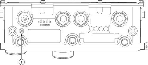
Reset Button
A 1500 series access point has a reset button located on the bottom of the unit. The reset button is recessed in a small hole that is sealed with a screw and a rubber gasket. The reset button can be used to perform the following functions:
- Reset the access point—Press the reset button for less than 10 seconds, and the LEDs turn off during the reset and then reactivate when the reset is complete.
- Disable battery backup power—Press the reset button for more than 10 seconds, and the LEDs turn off, then on, and then stay off.
- Switch off LEDs—Press the reset button for more than 10 seconds, and the LEDs turn off, then on, and then stay off.
Resetting Access Point
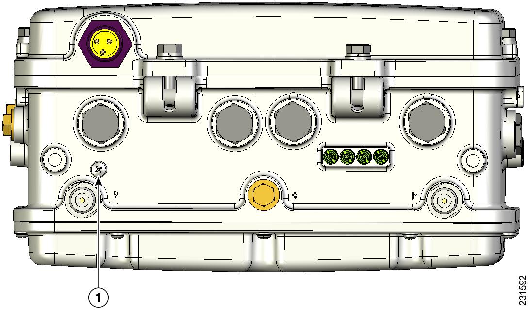
Monitoring the LED Status
The four-status LEDs on AP1500s are useful during the installation process to verify connectivity, radio status, access point status, and software status. However, once the access point is up and running and no further diagnosis is required, we recommend that you turn off the LEDs to discourage vandalism.
If your access point is not working as expected, see the LEDs at the bottom of the unit. You can use them to quickly assess the status of the unit.
NoteLEDs are enabled or disabled using the config ap led-state {enable | disable} {cisco_ap_name | all} command.
There are four LED status indicators on AP1500s.
Figure 7. Access Point LEDs at the Bottom of the Unit. This figure shows the location of the AP1500 LEDs.The table below describes each LED and its status.
RF-1 LED—Status of the radio in slot 0 (2.4-GHz) and slot 2 (5.8-GHz for 1524SB and 4.9-GHz for 1524PS)).
RF-2 LED—Status of the radio in slot 1 (5.8-GHz) and the radio in slot 3.1
1 Slot 3 is disabledTable 1 lists the access point LED signals.
2 If all LEDs are off, the access point has no power.3 When the access point power supply is initially turned on, all LEDs are amber.Serial Backhaul Access Point Guidelines for the Rest of the World (ROW)
In the 7.0 release, new 1524 SKUs are released, with both 802.11a radio units supporting the entire 5-GHz band from 4.9 GHz to 5.8 GHz. This release also opens the 5-GHz band for the -A domain as well on the existing hardware. The radios can also operate in UNII-2 (5.25 to 5.35 GHz), UNII-2 plus (5.47 to 5.725 GHz), and the upper ISM (5.725 to 5.850 GHz) bands.
The public safety band (4.94 to 4.99 GHz) is not supported for backhaul and for client access.
For information about the channels and maximum power levels of the AP1500 supported within the world's regulatory domains, see the Channels and Maximum Power Settings for Cisco Aironet Lightweight Access Points manual at:
- AP1520: http://www.cisco.com/en/US/docs/wireless/access_point/channels/lwapp/reference/guide/1520_chp.html
- AP1550: http://www.cisco.com/en/US/docs/wireless/access_point/channels/lwapp/reference/guide/1550pwr_chn_7dot3.pdf
Table 1 provides a complete overview of channels supported in each domain. In addition to 5 channels in the upper ISM band, there are 4 channels in the UNII-2 band and 11 channels in the UNII-2 Plus band. For outdoor APs, there are 5 channels in the upper ISM band, 3 channels in the UNII-2 band, and 8 channels in the UNII-2 Plus band.
Table 4 Channels Supported Per Regulatory Domain
Note Channels marked Yes/DFS are channels supported in that domain. Channels marked DFS are additional DFS-enabled channels and require checks for radar detection. This table is for up to 8 -Bi antennas. For higher gain antennas, see http://www.cisco.com/en/US/docs/wireless/access_point/channels/lwapp/reference/guide/1520_chp.html. For more information about AP1550 series RF Tx power levels, see http://www.cisco.com/en/US/docs/wireless/access_point/channels/lwapp/reference/guide/1550pwr_chn_7dot3.pdf.
With the expansion of the channel set, DFS-enabled channels are also supported. Radar detection and automatic channel reassignment in case of radar detection on RAP/MAPs are also supported. When there is a channel change, it is also propagated to the corresponding parent/child access point (if applicable) so that the channel change is synchronized between the parent and child so that there is no link downtime. For example, if radar is detected on the uplink radio of a child access point, the parent is informed so that it can change the channel of the downlink radio. The parent in turn informs the child about the channel change, so that the child access point can set the new channel on its uplink radio as well and does not have to scan again to rejoin the parent on the new channel.
For countries in the Middle East such as Saudi Arabia and Kuwait, a new regulatory domain for outdoor APs, the -M domain, has been mandated. With this release, outdoor APs will now support this new -M domain. Earlier, these countries were part of the -E domain, which supported a channel set of 100 to 140. However, in the -M domain, channels 149 to 161 are also supported with the 100 to 140 band. Also, in the -M domain, channels 149 to 161 are DFS enabled, unlike other domains such as -A, -C, -N, and so on, where these channels are non-DFS. Radar detection is also enabled on these channels. Because the countries that are now part of the -M domain (that is, Saudi Arabia and Kuwait) were earlier part of the -E domain, both the -E domain and the -M domain APs are supported, when any of these countries is configured on the controller, which ensures backward compatibility with the existing -E domain APs in these countries. However, you will have to ensure that only a valid set of channels (the channels common to both the -E and the -M domains) is selected as part of the 802.11a DCA list, and that the backhaul channel deselection feature is enabled to ensure correct operation of the -E domain APs, as these APs can support 100 to 140 channels and not the extended list of 149 to 161 channels available in the -M domain.
Discontinuation of the 116 and 132 Channels from the UNII-2 Extended Band
With the 7.0 release, in AP1522 and AP1524SB platforms, in addition to the 5 channels in the upper ISM band, there are 3 channels in the UNII-2 band and 8 channels in the UNII-2 Extended band. There are 11 channels in the UNII-2 Extended band, but only 8 are applicable in the outdoors due to stringent dynamic frequency selection (DFS) conditions for Canada because Canada requires a channel availability check every 10 minutes compared to every 60 seconds in the USA. The 120 (5600 MHz), 124 (5620 MHz), and 128 (5640 MHz) channels have had to be dropped.
The Federal Communications Commission (FCC) has issued a guideline to protect Terminal Doppler Weather Radar (TDWR) systems operating in the 5600- to 5650-MHz band from interference. Also, the UNII-2 Wi-Fi operating channels are interfering with the TDWR band. Therefore, with the 7.0.116.0 release, the 116 and 132 channels are dropped in addition to the 120, 124, and 128 channels. The guidelines also require that you avoid operation in the TDWR band and operate at least 30 MHz away from the TDWR operation frequencies when devices are installed within 35 km (about 21 miles) or the line-of-sight of the TDWR sites.
NoteYour outdoor installation should be registered in the outdoor database. No fee is required to register your company. The TDWR location sites can be found on the Internet.
NoteThe FCC, the National Telecommunications and Information Administration (NTIA), and the Federal Aviation Administration (FAA) are continuing to investigate and eliminate cases of interference to TDWRs. For more information about FCC guidelines for outdoor installations, see http://www.cisco.com/en/US/prod/collateral/routers/ps272/data_sheet_c78-647116_ps11451_Products_Data_Sheet.html.
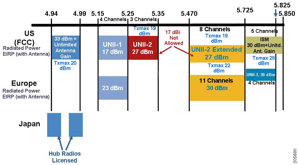
Frequency Bands
Both the 2.4-GHz and 5-GHz frequency bands are supported on the indoor and outdoor access points. Additionally, the 4.9-GHz public safety band is supported on AP1524PS.
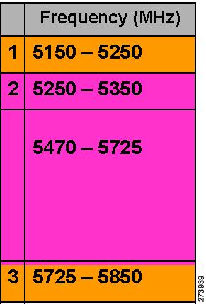
The 5-GHz band is a conglomerate of three bands in the USA: 5.150 to 5.250 (UNII-1), 5.250 to 5.350 (UNII-2), 5.470 to 5.725 (UNII-2 Extended), and 5.725 to 5.850 (ISM). UNII-1 and the UNII-2 bands are contiguous and are treated by 802.11a as being a continuous swath of spectrum 200-MHz wide, more than twice the size of the 2.4-GHz band (see Table 1).
The 4.9 GHz is a public safety channel within the 5-MHz (channels 1 to 10), 10-MHz (channels 11 to 19), and 20-MHz (channels 20 to 26) bandwidths.
The –D domain, which is the country domain for India, supports the following:
NoteThe frequency depends on the regulatory domain in which the access point is installed. For additional information, see the Channels and Power Levels document at http://www.cisco.com/en/US/docs/wireless/access_point/channels/lwapp/reference/guide/lw_chp2.html.
Table 5 Frequency Band UNII-14
Regulations for UNII devices operating in the 5.15- to 5.25-GHz frequency band. Indoor operation only,
Regulations for UNII devices operating in the 5.25- to 5.35-GHz frequency band. DFS and TPC are mandatory in this band.
1130, 1240, all 11n indoor APs, 1522, 1524SB, and 1552 (except -A domain)
Regulations for UNII-2 devices operating in the 5.470 to 5.725 frequency band.
ISM5
Regulations for UNII devices operating in the 5.725 to 5.850 GHz frequency band.
1130, 1240, all 11n indoor APs, 1522, 1524 (AP1524PS and AP1524SB), 1552
4 UNII refers to the Unlicensed National Information Infrastructure.5 SM refers to Industrial Science and Mechanical.For regulatory information, see http://www.cisco.com/en/US/prod/collateral/wireless/ps5679/ps5861/product_data_sheet0900aecd80537b6a.html.
Dynamic Frequency Selection
Previously, devices employing radar operated in frequency subbands without other competing services. However, controlling regulatory bodies are attempting to open and share these bands with new services like wireless mesh LANs (IEEE 802.11).
To protect existing radar services, the regulatory bodies require that devices wishing to share the newly opened frequency subband behave in accordance with the Dynamic Frequency Selection (DFS) protocol. DFS dictates that to be compliant, a radio device must be capable of detecting the presence of radar signals. When a radio detects a radar signal, it is required to stop transmitting to for at least 30 minutes to protect that service. The radio then selects a different channel to transmit on but only after monitoring it. If no radar is detected on the projected channel for at least one minute, then the new radio service device may begin transmissions on that channel.
The process for a radio to detect and identify a radar signal is a complicated task that sometimes leads to incorrect detects. Incorrect radar detections can occur due to a large number of factors, including due to uncertainties of the RF environment and the ability of the access point to reliably detect actual on-channel radar.
The 802.11h standard addresses DFS and Transmit Power Control (TPC) as it relates to the 5-GHz band. Use DFS to avoid interference with radar and TPC to avoid interference with satellite feeder links.
NoteDFS is mandatory in the USA for 5250 to 5350 and 5470 to 5725 frequency bands. DFS and TPC are mandatory for these same bands in Europe.
Antennas
Overview
Antenna choice is a vital component of any wireless network deployment. There are two broad types of antennas:
Each type of antenna has a specific use and is most beneficial in specific types of deployments. Because antennas distribute RF signal in large lobed coverage areas determined by antenna design, successful coverage is heavily reliant on antenna choice.
An antenna gives a mesh access point three fundamental properties: gain, directivity, and polarization:
- Gain—A measure of the increase in power. Gain is the amount of increase in energy that an antenna adds to an RF signal.
- Directivity—The shape of the transmission pattern. If the gain of the antenna increases, the coverage area decreases. The coverage area or radiation pattern is measured in degrees. These angles are measured in degrees and are called beamwidths.
- Polarization—The orientation of the electric field of the electromagnetic wave through space. Antennas can be polarized either horizontally or vertically, though other kinds of polarization are available. Both antennas in a link must have the same polarization to avoid an additional unwanted loss of signal. To improve the performance, an antenna can sometimes be rotated to alter polarization, which reduces interference. A vertical polarization is preferable for sending RF waves down concrete canyons, and horizontal polarization is generally more preferable for wide area distribution. Polarization can also be harnessed to optimize for RF bleed-over when reducing RF energy to adjacent structures is important. Most omnidirectional antennas ship with vertical polarization as their default.
Antenna Options
A wide variety of antennas are available to provide flexibility when you deploy the mesh access points over various terrains. 5 GHz is used as a backhaul and 2.4 GHz is used for client access.
Table 1 lists the supported external 2.4- and 5-GHz antennas for AP1500s.
Table 6 External 2.4- and 5-GHz Antennas 2.4-GHz compact omnidirectional6
5-GHz compact omnidirectional7
4.9-GHz compact omnidirectional8
See the Cisco Aironet Antenna and Accessories Reference Guide on Cisco antennas and accessories at http://www.cisco.com/en/US/prod/collateral/wireless/ps7183/ps469/product_data_sheet09186a008008883b.html
The deployment and design, limitations and capabilities, and basic theories of antennas as well as installation scenarios, regulatory information, and technical specifications are addressed in detail.
Table 2 summarizes the horizontal and vertical beamwidth for Cisco antennas.
N-Connectors
All external antennas are equipped with male N-connectors.
AP1552 E/H have three N-connectors to connect dual-band antennas.
AP1552 C/I have no N-connectors as they come with inbuilt antennas.
AP1522 has three separate N-connectors to attach two 2.4-GHz antennas and one N-connector for a 5- GHz antenna.
AP1524PS and AP1524SB have five N connectors to attach three 2.4-GHz antennas and two N connectors for 5-GHz/4.9-GHz bands.
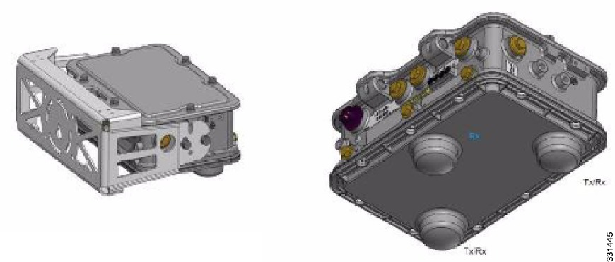
Each radio has at least one TX/RX port. Each radio must have an antenna connected to at least one of its available TX/RX ports.
Antenna locations for 5.8 GHz, 4.9 GHz, and 2.4 GHz are fixed and labeled.
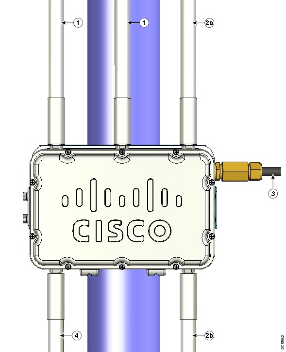
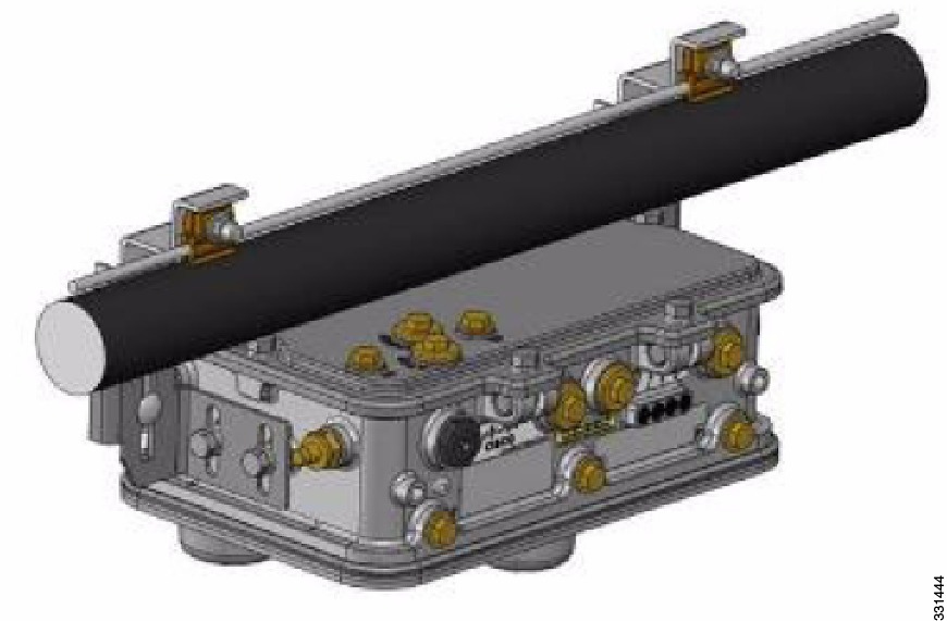
Figure 10. 1522C Two Radio Cable Mesh Access Point Configuration (Hinged-Side Facing Forward). This figure shows antenna placement for a two-radio cable mesh access point.
Clamp bracket with cable clamps (part of strand mount kit, ordered separately)
5-GHz antenna9 (Tx/Rx)
2.4-GHz antennas10 (Tx/Rx)
Cable POC power input11
Strand mount bracket (part of strand mount kit, ordered separately)
Antenna Configurations for 1552
The 1552 access point supports the following two types of antennas designed for outdoor use with radios operating in the 2.4-GHz and 5-GHz frequency:
- Cisco Aironet Low Profile Dual-Band 2.4/5 GHz Dipole Antenna Array (CPN 07-1123-01), an integrated array of three dual-band dipole antennas
- Cisco Aironet Dual-Band Omnidirectional Antenna (AIR-ANT2547V-N), referred to as “stick” antennas
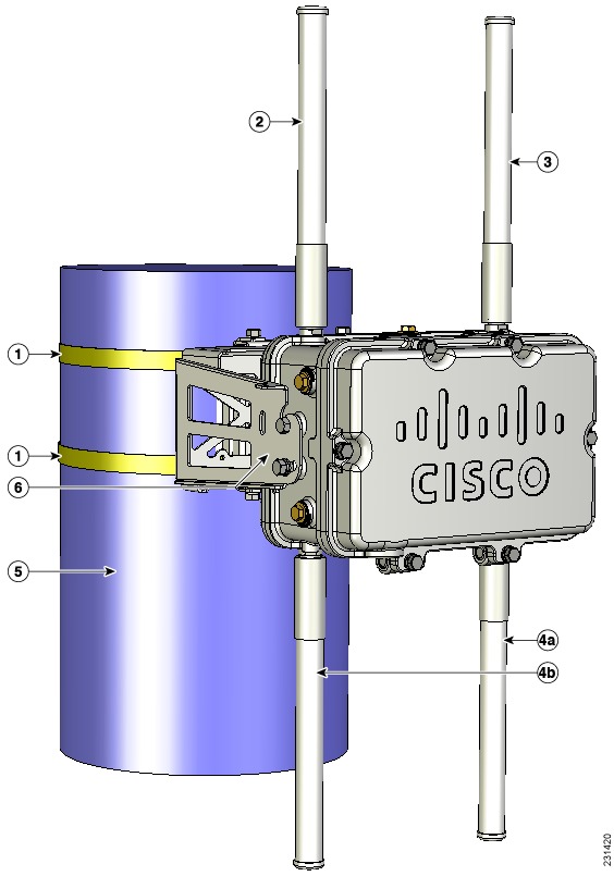
Two types of mounting configurations are available: the cable strand mount and the pole mount.
The 1552 models C and I access points are equipped with three new integrated dual-band antennas, with 2 dBi gain at 2.4 GHz and 4 dBi gain at 5 GHz. The antenna works in cable strand mount and low cost, low profile applications.
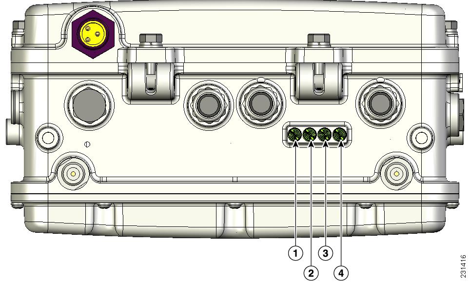
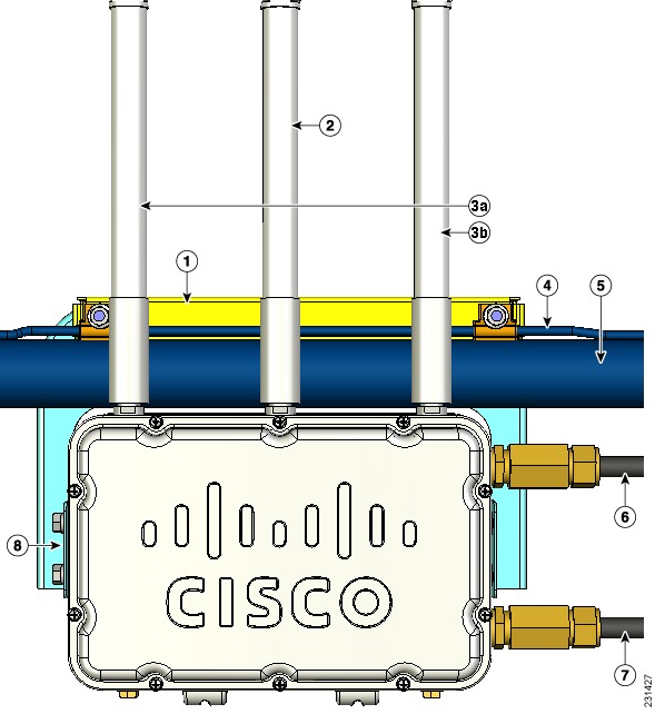
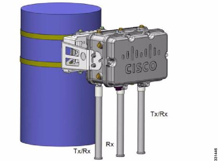
The 1552 E and H access points are equipped with three N-type radio frequency (RF) connectors (antenna ports 4, 5, and 6) on the bottom of the unit for external antennas to support multiple input multiple output (MIMO) operation as shown in the figure below. When using the optional Cisco Aironet AIR-ANT2547V-N Dual-Band Omnidirectional Antenna, the 2.4- and 5-GHz antennas connect directly to the access point. These antennas have 4 dBi gain at 2.4 GHz and 7 dBi gain at 5 GHz.
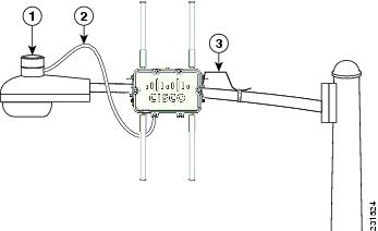
Figure 16. Outdoor Pole-top Installation of a Mesh Access Point. This figure shows one of the recommended installations of an outdoor AP1500.The AP1500 series was designed building on the long experience we have had in deploying outdoor access points over the past few years. This includes consideration for resistance to lightning effects. The AP1500 series employs some lightning arrestor circuitry on the Ethernet & Power ports. On input Ethernet port, Gas Discharge Tubes (GDT) are used on the Power Entry Module (PEM) to mitigate lightning effect. On the AC Power, GDTs are also used along with fuses to mitigate a high-current condition. For the DC power, a fuse is used to mitigate a high-current condition.
While not a common practice, users may want to consider adding additional lightning protection at the antenna ports for added protection.
Client Access Certified Antennas (Third-Party Antennas)
You can use third-party antennas with AP1500s. However, note the following:
- Cisco does not track or maintain information about the quality, performance, or reliability of the noncertified antennas and cables.
- RF connectivity and compliance is the customer’s responsibility.
- Compliance is only guaranteed with Cisco antennas or antennas that are of the same design and gain as Cisco antennas.
- Cisco Technical Assistance Center (TAC) has no training or customer history with regard to nonCisco antennas and cables.
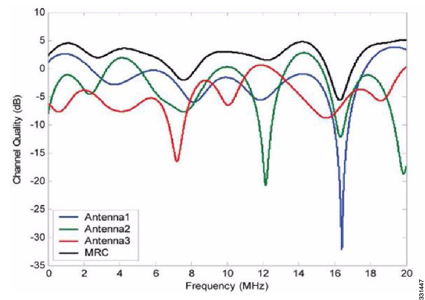
Maximum Ratio Combining
To understand how this works, consider a single transmitter 802.11a/g client sending an uplink packet to an 802.11n access point with multiple transceivers. The access point receives the signal on each of its three receive antennas.
Each received signal has a different phase and amplitude based on the characteristics of the space between the antenna and the client. The access point processes the three received signals into one reinforced signal by adjusting their phases and amplitudes to form the best possible signal. The algorithm used, called maximum ratio combining (MRC), is typically used on all 802.11n access points. MRC only helps in the uplink direction, enabling the access point to "hear" the client better.
For the 1520 Series
AP1520 radios have a much higher transmit power, better receiver sensitivity, and broader outdoor temperature range as compared to AP1510 and AP1505 mesh access points.
- The 5-GHz radio (802.11a) is a Single-in-Single-Out (SISO) architecture and the 2.4-GHz radio (802.11 b/g) is 1x3 Single-in-Multiple-Out (SIMO) architecture.
- The 2.4-GHz radio has one transmitter and three receivers. Output power is configurable to 5 levels. With its 3 receivers enabling maximum-ratio combining (MRC), this radio has better sensitivity and range than a typical SISO 802.11b/g radio for OFDM rates.
When operating with data rates higher than 12 Mbps, you can increase gain on a 2.4-GHz radio to 2.7 dB by adding two antennas and to 4.5 dB, by adding three antennas. For information about RX sensitivities and MRC gain, see Table 1.
For the 1550 Series
In the 1552 series mesh access point, MRC gain is different than the 1520 series mesh access points. The 1520 series access points do not have 802.11n functionality. In the 2.4-GHz band, it has only one transmitter and up to three receivers. Therefore, it is SIMO (Single in Multiple out) in 2.4 GHz. In the 5-GHz band, it has only one transmitter and one receiver. Therefore, it is SISO (Single in Single out) in the 5-GHz band. The MRC gain is important only for the 2.4-GHz radio in the 1552 access points. The MRC is not available for the 5-GHz radio. The 2.4-GHz radio has one Tx and up to three Rx antennas depending on the AP configuration.
In the 1522 access points, users have an option to use one, two, or three 2.4-GHz Rx antennas. With this option, users get around 3 dB MRC gain with 2 Rx antennas and a 4.5-dB MRC gain with 3 Rx antennas for data rates of 24 Mbps or higher.
For the 1552 access points, both the 2.4- and 5-GHz radios are 2x3 MIMO. Therefore, they have two transmitters and three receivers. Because the antennas are dual band and there is no option to have less than three Rx antennas, the MRC is added to the RX sensitivity always as it is embedded into the baseband chipset.
The number for typical Rx sensitivity in our customer data sheet assume 3 Rx antennas for both the 1520 and the 1550 series access points.
With the chipset used in the AP1520 series radios, there was a start-of-packet problem at lower data rates that wiped out the gain. Therefore, the MRC gain became useful from a data rate of 12 Mbps onwards in the 1520 series access points. This problem has been corrected in the current chipset used in the 1552 access points. The MRC gain has improved for lower data rates as well in the 1552 access points. You get a 4.7-dB improvement in sensitivity with the 2x3 MIMO radio over a 1x1 SISO implementation.
Table 2 and Table 3 list the MRC gain for the AP1552 11a/g and AP1552 11n respectively.
Cisco 1500 Hazardous Location Certification
The standard AP1500 enclosure is a ruggedized, hardened enclosure that supports the NEMA 4X and IP67 standards for protection to keep out dust, damp and water.
Hazardous Certification (Class 1, Div 2, and Zone 2)
To operate in occasional hazardous environments, such as oil refineries, oil fields, drilling platforms, chemical processing facilities, and open-pit mining, special certification is required and the certification is labeled as Class 1, Div 2, or Zone 2.
NoteFor USA and Canada, this certification is CSA Class 1, Division 2. For Europe (EU), it is ATEX or IEC Class 1, Zone 2.
Cisco has Hazardous Certified SKUs for USA and EU: AIR-LAP1522HZ-x-K9, AIR-LAP1524HZ-x-K9, and AIR-LAP1552H-x-K9. These SKUs are modified, as per the certification requirements. The hazardous locations certificate requires that all electrical power cables be run through conduit piping to protect against accidental damage to the electrical wiring that could cause a spark and possible explosion. Access points for hazardous locations contain an internal electrical mounting connect that receives discrete wires from a conduit interface coupler entering from the side of the housing. After the electrical wiring is installed, a cover housing is installed over the electrical connector to prevent exposure to the electrical wiring. The outside of the housing has a hazardous location certification label (CSA, ATEX, or IEC) that identifies the type of certifications and environments that the equipment is approved for operation.
Hazardous Certification (Div 1 > Div 2 and Zone 1 > Zone 2)
Class 1, Division 1/Zone 1 is for environments with full-time ignitable concentrations of flammable gases, vapors, or liquids. To meet the requirements of the Div 1 > Div 2 and Zone 1 > Zone 2 locations, we recommend a TerraWave Solutions CSA certified protective Wi-Fi enclosure (see Table 1).
For more information about the TerraWave enclosures, see http://www.tessco.com/yts/partner/manufacturer_list/vendors/terrawave/pdf/terrawavehazardouesenclosuresjan08.pdf
Table 2 lists the hardware features across different AP1500 models at a glance.
NotePoE-in is not 802.3af and does not work with PoE 802.3af-capable Ethernet switch. It requires Power Injector.
Cisco Wireless LAN Controllers
The wireless mesh solution is supported on Cisco 2500, 5500, and 8500 Series Wireless LAN Controllers.
For more information about the Cisco 2500, 5500, and 8500 Series Wireless LAN Controllers, see http://www.cisco.com/en/US/products/ps6302/Products_Sub_Category_Home.html.
Cisco Prime Infrastructure
The Cisco Prime Infrastructure provides a graphical platform for wireless mesh planning, configuration, and management. Network managers can use the Prime Infrastructure to design, control, and monitor wireless mesh networks from a central location.
With the Prime Infrastructure, network administrators have a solution for RF prediction, policy provisioning, network optimization, troubleshooting, user tracking, security monitoring, and wireless LAN systems management. Graphical interfaces make wireless LAN deployment and operations simple and cost-effective. Detailed trending and analysis reports make the Prime Infrastructure vital to ongoing network operations.
The Prime Infrastructure runs on a server platform with an embedded database, which provides scalability that allows hundreds of controllers and thousands of Cisco mesh access points to be managed. Controllers can be located on the same LAN as the Prime Infrastructure, on separate routed subnets, or across a wide-area connection.
Architecture
- Control and Provisioning of Wireless Access Points
- XML Configuration File
- Adaptive Wireless Path Protocol
Control and Provisioning of Wireless Access Points
Control and provisioning of wireless access points (CAPWAP) is the provisioning and control protocol used by the controller to manage access points (mesh and nonmesh) in the network. In release 5.2, CAPWAP replaced lightweight access point protocol (LWAPP).
CAPWAP Discovery on a Mesh Network
The process for CAPWAP discovery on a mesh network is as follows:
- A mesh access point establishes a link before starting CAPWAP discovery, whereas a nonmesh access point starts CAPWAP discovery using a static IP for the mesh access point, if any.
- The mesh access point initiates CAPWAP discovery using a static IP for the mesh access point on the Layer 3 network or searches the network for its assigned primary, secondary, or tertiary controller. A maximum of 10 attempts are made to connect.
NoteThe mesh access point searches a list of controllers configured on the access point (primed) during setup.
- If Step 2 fails after 10 attempts, the mesh access point falls back to DHCP and attempts to connect in 10 tries.
- If both Steps 2 and 3 fail and there is no successful CAPWAP connection to a controller, then the mesh access point falls back to LWAPP.
- If there is no discovery after attempting Steps 2, 3, and 4, the mesh access point tries the next link.
Dynamic MTU Detection
If the MTU is changed in the network, the access point detects the new MTU value and forwards that to the controller to adjust to the new MTU. After both the access point and the controller are set at the new MTU, all data within their path are fragmented into the new MTU. The new MTU size is used until it is changed. The default MTU on switches and routers is 1500 bytes.
XML Configuration File
Mesh features within the controller’s boot configuration file are saved in an XML file in ASCII format. The XML configuration file is saved in the flash memory of the controller.
CautionDo not edit the XML file. Downloading a modified configuration file onto a controller causes a cyclic redundancy check (CRC) error on boot and the configuration is reset to the default values.
You can easily read and modify the XML configuration file by converting it to CLI format. To convert from XML to CLI format, upload the configuration file to a TFTP or an FTP server. The controller initiates the conversion from XML to CLI during the upload.
Once on the server, you can read or edit the configuration file in CLI format. Then, you can download the file back to the controller. The controller converts the configuration file back to XML format, saves it to flash memory, and reboots using the new configuration.
The controller does not support uploading and downloading of port configuration CLI commands. If you want to configure the controller ports, enter the relevant commands summarized below:
CLI commands with known keywords and proper syntax are converted to XML while improper CLI commands are ignored and saved to flash memory. Any field with an invalid value is filtered out and set to a default value by the XML validation engine.Validation occurs during bootup.
To see any ignored commands or invalid configuration values, enter the following command:
Access passwords are hidden (obfuscated) in the configuration file. To enable or disable access point or controller passwords, enter the following command:
Adaptive Wireless Path Protocol
The Adaptive Wireless Path Protocol (AWPP) is designed specifically for wireless mesh networking to provide ease of deployment, fast convergence, and minimal resource consumption.
AWPP takes advantage of the CAPWAP WLAN, where client traffic is tunneled to the controller and is therefore hidden from the AWPP process. Also, the advance radio management features in the CAPWAP WLAN solution are available to the wireless mesh network and do not have to be built into AWPP.
AWPP enables a remote access point to dynamically find the best path back to a RAP for each MAP that is part of the RAP’s bridge group (BGN). Unlike traditional routing protocols, AWPP takes RF details into account.
To optimize the route, a MAP actively solicits neighbor MAP. During the solicitation, the MAP learns all of the available neighbors back to a RAP, determines which neighbor offers the best path, and then synchronizes with that neighbor. The path decisions of AWPP are based on the link quality and the number of hops.
AWPP automatically determines the best path back to the CAPWAP controller by calculating the cost of each path in terms of the signal strength and number of hops. After the path is established, AWPP continuously monitors conditions and changes routes to reflect changes in conditions. AWPP also performs a smoothing function to signal condition information to ensure that the ephemeral nature of RF environments does not impact network stability.
Traffic Flow
The traffic flow within the wireless mesh can be divided into three components:
- Overlay CAPWAP traffic that flows within a standard CAPWAP access point deployment; that is, CAPWAP traffic between the CAPWAP access point and the CAPWAP controller.
- Wireless mesh data frame flow.
- AWPP exchanges.
As the CAPWAP model is well known and the AWPP is a proprietary protocol, only the wireless mesh data flow is described. The key to the wireless mesh data flow is the address fields of the 802.11 frames being sent between mesh access points.
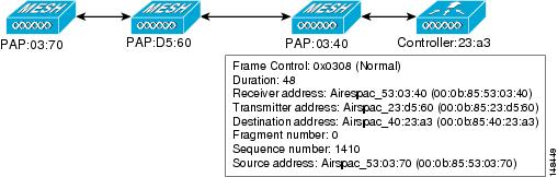
An 802.11 data frame can use up to four address fields: receiver, transmitter, destination, and source. The standard frame from a WLAN client to an AP uses only three of these address fields because the transmitter address and the source address are the same. However, in a WLAN bridging network, all four address fields are used because the source of the frame might not be the transmitter of the frame, because the frame might have been generated by a device behind the transmitter.
Figure 1 shows an example of this type of framing. The source address of the frame is MAP:03:70, the destination address of this frame is the controller (the mesh network is operating in Layer 2 mode), the transmitter address is MAP:D5:60, and the receiver address is RAP:03:40.
As this frame is sent, the transmitter and receiver addresses change on a hop-by-hop basis. AWPP is used to determine the receiver address at each hop. The transmitter address is known because it is the current mesh access point. The source and destination addresses are the same over the entire path.
If the RAP’s controller connection is Layer 3, the destination address for the frame is the default gateway MAC address, because the MAP has already encapsulated the CAPWAP in the IP packet to send it to the controller, and is using the standard IP behavior of using ARP to find the MAC address of the default gateway.
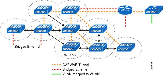
Each mesh access point within the mesh forms an CAPWAP session with a controller. WLAN traffic is encapsulated inside CAPWAP and is mapped to a VLAN interface on the controller. Bridged Ethernet traffic can be passed from each Ethernet interface on the mesh network and does not have to be mapped to an interface on the controller (see Figure 2).
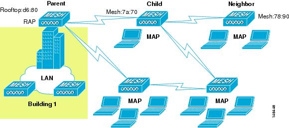
Mesh Neighbors, Parents, and Children
Relationships among mesh access points are as a parent, child, or neighbor (see Figure 1).
- A parent access point offers the best route back to the RAP based on its ease values. A parent can be either the RAP itself or another MAP.
- A child access point selects the parent access point as its best route back to the RAP.
- A neighbor access point is within RF range of another access point but is not selected as its parent or a child because its ease values are lower than that of the parent.
Criteria to Choose the Best Parent
AWPP follows this process in selecting parents for a RAP or MAP with a radio backhaul:
- A list of channels with neighbors is generated by passive scanning in the scan state, which is a subset of all backhaul channels.
- The channels with neighbors are sought by actively scanning in the seek state and the backhaul channel is changed to the channel with the best neighbor.
- The parent is set to the best neighbor and the parent-child handshake is completed in the seek state.
- Parent maintenance and optimization occurs in the maintain state.
This algorithm is run at startup and whenever a parent is lost and no other potential parent exists, and is usually followed by CAPWAP network and controller discovery. All neighbor protocol frames carry the channel information.
Parent maintenance occurs by the child node sending a directed NEIGHBOR_REQUEST to the parent and the parent responding with a NEIGHBOR_RESPONSE.
Parent optimization and refresh occurs by the child node sending a NEIGHBOR_REQUEST broadcast on the same channel on which its parent resides, and by evaluating all responses from neighboring nodes on the channel.
A parent mesh access point provides the best path back to a RAP. AWPP uses ease to determine the best path. Ease can be considered the opposite of cost, and the preferred path is the path with the higher ease.
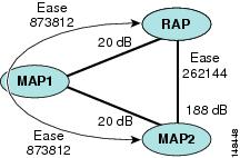
Ease Calculation
Ease is calculated using the SNR and hop value of each neighbor, and applying a multiplier based on various SNR thresholds. The purpose of this multiplier is to apply a spreading function to the SNRs that reflects various link qualities.
Figure 1 shows the parent path selection where MAP2 prefers the path through MAP1 because the adjusted ease value (436906) though this path is greater then the ease value (262144) of the direct path from MAP2 to RAP.
SNR Smoothing
One of the challenges in WLAN routing is the ephemeral nature of RF, which must be considered when analyzing an optimal path and deciding when a change in path is required. The SNR on a given RF link can change substantially from moment to moment, and changing route paths based on these fluctuations results in an unstable network, with severely degraded performance. To effectively capture the underlying SNR but remove moment-to-moment fluctuations, a smoothing function is applied that provides an adjusted SNR.
In evaluating potential neighbors against the current parent, the parent is given 20 percent of bonus-ease on top of the parent's calculated ease, to reduce the ping-pong effect between parents. A potential parent must be significantly better for a child to make a switch. Parent switching is transparent to CAPWAP and other higher-layer functions.