-
Cisco CDA Visual Quality Experience Application User Guide Release 3.7
-
Preface
-
Introduction to Cisco CDA-VQE Application
-
Inital VQE Configuration
-
Using the VQE Channel Provisioning Tool
-
Using the VQE-S AMT
-
Using the VCDS AMT
-
Troubleshooting VQE Software Components
-
Configuring VQE Server and VQE Tools
-
VQE System and Network Parameters
-
SNMP MIBs
-
VQE System Messages
-
Manual Initial VQE System Configuration
-
Configuring DHCP and DNS Servers for VCDS
-
Using the vcds_send_file Command
-
Changing the Boot Sequence to start from CD/DVD Drive
-
VQE Server Performance and Scaling Limits
-
VCPT Configuration Files
-
Using IPMI on Cisco CDE 250
-
 Feedback
Table Of Contents
Web Browser, Screen Resolution, and Other Requirements
Configuring Terminal Emulation Software
Security Restrictions for Logins and Root Privileges
Using the Cisco VQE Configuration Tool for SSL Certificates
Creating Your Own Certificate Authority
Generating and Deploying Your Own SSL Certificates
Generating a Certificate-Signing Request
Signing the Certificate-Signing Request
Installing the Certificates, Private Key, and Keystore
Deploying Commercial SSL Certificates
Commercial CA: Installing the Certificates, Private Key, and Keystore
VQE-S and VQE-Tools Server: Routing and Interface Configuration Overview
Bond Interfaces on a VQE-S and VQE-Tools Server
Types of Routes on a VQE-Tools Server
Using Dedicated or Shared Interfaces for VQE-S Ingest Traffic and for VQE-S Services Traffic
Routing Configuration for Dedicated Interfaces and Shared Interfaces
Interface for a Management Network
Load Balancing and Redundancy with Multiple VQE-S
Configuring LACP Bonding on a VQE-S and VQE Tools Server
Configuring VLAN Support on a VQE-S and VQE-Tools Server
Using the VQE Configuration Tool
VQE Configuration Tool Root Menu
On the VQE-S Host: Verifying the Status of the VQE and System Services
On the VQE Tools Host: Verifying the Status of the VQE and System Services
Configuring the VQE-S RTCP Exporter
Configuring VQE-S RTCP Exporter via manually editing the VCDB File
Configuring VQE-S RTCP Exporter via VQE Configuration Tool
Configuring the Other Parameters for the VQE-S Host
Configuring the Edge Router for VQE-S
For Bond Interfaces: Guidance for Configuring Bond Interface on the Attached Router
For OSPF Routing: Guidance for Configuring the Attached Router
For Static Routes: Guidance for Configuring the Feedback Targets on the Attached Router
Initial VQE Configuration
This chapter explains the initial configuration tasks needed to get the two categories of Cisco CDE servers running with the Cisco VQE software:
•
VQE server (VQE-S)—CDE hosting VQE-S
•
In a VQE deployment, use of the VQE Tools server with the VCPT and the VCDS is optional.
For information on installing or upgrading VQE software, see Release Notes for Cisco CDA Visual Quality Experience Application 3.7.
Note
For information on the manual initial VQE configuration tasks, see "Manual Initial VQE System Configuration."
Read the following sections for information on CDE configuration configuring a CDE:
•
•
•
•
•
•
•
•
•
•
•
Note
For information on upgrading a Cisco CDE, see Release Notes for Cisco CDA Visual Quality Experience Application, Release 3.7.
This chapter assumes that the Cisco CDE hardware has been installed as described in Cisco Content Delivery Engine 110 Hardware Installation Guide and the Cisco Content Delivery Engine 205/220/250/420 Hardware Installation Guide, including connecting cables and connecting power.
Web Browser, Screen Resolution, and Other Requirements
To access the VQE-S AMT, the VCDS AMT, or the VCPT, you need a web browser. For these tools, the following web browsers are supported:
•
•
The minimum screen resolution required for the VQE-S AMT, the VCDS AMT, and the VCPT is
1024 x 768 pixels.For the VQE-S AMT, Adobe Flash Player must be installed on the computer that hosts the browser accessing the VQE-S AMT. Adobe Flash Player is required to display the Channels Status Summary graph of active, inoperative, and inactive channels in the AMT VQE-S Status window. Adobe Flash Player is free and can be found at this URL:
http://get.adobe.com/flashplayer/
System Port Numbers
Table 2-1 presents the TCP ports used by the VQE-S, and displays the user of each port.
Table 2-1 VQE-S System Ports
21
FTP
22
SSH1
161
SNMP2
162
SNMP traps
443
HTTPS3
444
HTTPS push
8005
Apache tomcat
8009
Apache tomcat
8050
VQE process monitor
8051
8052
MLB6 RPC
8053
VCDS
8054
STUN Server RPC
1 SSH = Secure Shell.
2 SNMP = Simple Network Management Protocol.
3 HTTP = Hypertext Transfer Protocol Secure.
4 CP = control plane.
5 XML-RPC = XML remote procedure call.
6 MLB = multicast load balancer.
Ports 8005, 8009, 8050, 8051, 8052, 8053, and 8054 are not open for external use. All other ports listed in Table 2-1 are only accessible from a management interface. For information on management interfaces, see the "Interface for a Management Network" section.
Configuring Terminal Emulation Software
The RJ-45 serial ports on the Cisco CDE front and back panels can be used for administrative access to the CDE through a terminal server. Terminal emulation software must be configured as follows:
•
•
•
•
•
Security Restrictions for Logins and Root Privileges
For security reasons, the following restrictions apply to VQE:
•
•
If you want to add user accounts to the wheel group so that additional users can use su and sudo, log in as root and issue the following command:
[root@system]# usermod -G wheel usernameIn the preceding command syntax, username specifies the user who is added to the wheel group.
Prerequisites
Before you start the initial VQE software configuration, the following items should be accomplished for the CDE that hosts the VQE-S and the CDE that hosts the VQE Tools:
•
•
Connecting Cables to the CDE
The following cable connections are used on the Cisco CDE that hosts the VQE-S and on the CDE that hosts the VQE Tools:
•
Note
–
–
•
•
Note
•
For the location of connectors on the Cisco CDE front and back panels, see Cisco Content Delivery Engine 110 Hardware Installation Guide and the Cisco Content Delivery Engine 205/220/250/420 Hardware Installation Guide.
Setting Up SSL Certificates
SSL is used on the CDEs hosting the VQE-S and the VQE Tools server to create secure communication channels using Triple Data Encryption Standard (3DES) between web browsers and the VQE-S Application Monitoring Tool (AMT), the VCDS AMT, and the VCPT. SSL is also used by the VCPT when providing channel information to the VQE-S and the VCDS.
The HTTP server on the VQE-S and the VQE Tools server is not usable until the SSL certificates and other required SSL files are created and deployed. The VQE-S AMT, the VCDS AMT, and the VCPT require SSL certificates from a certificate authority (CA) to be created and deployed. The CA can be you or someone in your company, or a commercial CA, such as VeriSign. The procedures to create and deploy certificates are explained in the following sections:
•
•
•
•
You perform the procedures for deploying CA certificates on the VQE-S hosts and the VQE Tools hosts. As an alternative if you are setting up the certificates manually, you can create the needed files on one host and copy them to the other hosts.
The Open Source toolkit from the OpenSSL Project collaborative is used to generate, sign, and install your own CA certificates and to generate the Certificate-Signing Request for commercial certificates. The Open Source toolkit is installed on the VQE-S and the VQE Tools hosts. For more information on the Open Source toolkit and for documentation on toolkit commands, go to the following URL:
http://www.openssl.org
Using the Cisco VQE Configuration Tool for SSL Certificates
To manually create and deploy SSL certificates, follow the directions provided in these sections:
–
–
–
Creating Your Own Certificate Authority
Note
This task to create your own certificate authority (CA) is only performed once for all instances of the VQE-S and the VCPT. The CA that you create can be used to sign server certificates on all CDE servers hosting the VQE-S or the VQE Tools.
To create a CA certificate, perform the following steps:
Step 1
Note
Step 2
$ openssl genrsa -out ca.key 4096The openssl genrsa command saves the ca.key file in your current working directory.
The generated key is a 4096-bit RSA key, which is encrypted using Triple-DES and stored in PEM format so that it is readable as ASCII text.
Step 3
$ openssl req -new -x509 -days 3650 -key ca.key -out ca.crt
Note
The command prompts for the following X.509 attributes of the certificate. It is recommended that you provide valid input for X.509 information. Use a period (.) to indicate blank input.
•
•
•
•
•
•
The openssl req command saves the ca.crt file in your current working directory.
Generating and Deploying Your Own SSL Certificates
When you act as your own certificate authority, you can sign multiple Certificate-Signing Requests for the VQE-S hosts and the VCPT hosts. Generating and deploying your own SSL certificates involves three tasks:
1.
2.
3.
These tasks are explained in the following three sections. We recommend that these tasks be repeated for each CDE host so that there is a unique set of files generated for each host. You can create the needed sets of files on one host and copy them to the other hosts.
Generating a Certificate-Signing Request
To generate a Certificate-Signing Request, perform the following steps:
Note
Step 1
$ openssl genrsa -out server.key 1024The openssl genrsa command saves the server.key file in your current working directory.
Note
Step 2
$ openssl req -new -key server.key -out server.csrThe command prompts for the same X.509 attributes that were specified when you created your CA certificate in the "Creating Your Own Certificate Authority" section. It is recommended that you provide valid input for X.509 information. Use a period (.) to indicate blank input.
Note
The openssl req command saves the server.csr file in your current working directory.
The command creates a public/private key pair. The private key (server.key) is stored locally on the server machine and is used for decryption. The public portion, in the form of a Certificate-Signing Request (server.csr), is used for certificate enrollment with the CA.
Tip
Signing the Certificate-Signing Request
The Certificate-Signing Request can be signed by commercial CA entities, such as VeriSign, or by your own CA, as described in the "Creating Your Own Certificate Authority" section.
Note
We recommend that the system time of each CDE be synchronized with Network Time Protocol (NTP). The system time when the signing of the Certificate-Signing Request occurs must be later than the system time when the CA was created.
To sign the Certificate-Signing Request with the self-created certificate authority, enter the following command:
$ openssl x509 -req -days 3650 -in server.csr -CA ca.crt -CAkey ca.key -set_serial 01 -out
server.crt
Note
The openssl x509 command saves server.crt in your current working directory.
In the example above, the serial number of the signed server certificate is set to 01. Each time you execute this command, you must change the serial number, especially if you sign another certificate before a previously-signed certificate is expired.
Installing the Certificates, Private Key, and Keystore
The certificate needs to be in a certain format and reside in a designated directory to be used by the VQE-S-related or the VCPT-related software.
To install the server and CA certificates, the private key and the keystore, perform the following steps:
Step 1
$ cat server.crt ca.crt > stackedChain.pem
Note
The stackedChain.pem file content must be in this order:
-----BEGIN CERTIFICATE-----<SSL Server Cert Contents>-----END CERTIFICATE----------BEGIN CERTIFICATE-----<CA Cert Contents>-----END CERTIFICATE-----The following example shows the stackedChain.pem file:
-----BEGIN CERTIFICATE-----MIIDvjCCAaYCAQEwDQYJKoZIhvcNAQEFBQAwZTELMAkGA1UEBhMCVVMxDTALBgNV... Omitted contents .../kzgDk5wO1CbTwuxPIY1piy0Os1Q5EWk3VVAmv4tNMT9bANeKDUiVyYyOi1NIiHA36w=-----END CERTIFICATE----------BEGIN CERTIFICATE-----MIIGGDCCBACgAwIBAgIJAPtvlrCRokk4MA0GCSqGSIb3DQEBBQUAMGUxCzAJBgNV... Omitted contents ...KV+sxNECGE40iWIvd1dXDA1O34qhAwkVD6/bxw==-----END CERTIFICATE-----
Note
Step 2
$ keytool -import -keystore trustedca - alias rootca -file ca.crtThe CA certificate (ca.crt) specified in the -file argument is the CA certificate that you created in the "Creating Your Own Certificate Authority" section.
The keytool command creates a new keystore with the CA certificate. The resulting file is named trustedca.
Step 3
•
–
–
•
–
–
–
Deploying Commercial SSL Certificates
As an alternative to acting as your own certificate authority (CA), commercial certificate authorities, such as VeriSign, can issue and sign Secure Sockets Layer (SSL) certificates.
Deploying a commercial certificate involves the following steps:
1.
2.
3.
Commercial CA: Installing the Certificates, Private Key, and Keystore
When you get the signed certificates back from the commercial CA, you need to install them and the private key and keystore.
To install the certificates, private key, and keystore, follow these steps:
Step 1
$ cat server.crt ca.crt > stackedChain.pem
Note
The stackedChain.pem file content must be in this order:
-----BEGIN CERTIFICATE-----<SSL Server Cert Contents>-----END CERTIFICATE----------BEGIN CERTIFICATE-----<CA Cert Contents>-----END CERTIFICATE-----The following example shows the stackedChain.pem file:
-----BEGIN CERTIFICATE-----MIIDvjCCAaYCAQEwDQYJKoZIhvcNAQEFBQAwZTELMAkGA1UEBhMCVVMxDTALBgNV... Omitted contents .../kzgDk5wO1CbTwuxPIY1piy0Os1Q5EWk3VVAmv4tNMT9bANeKDUiVyYyOi1NIiHA36w=-----END CERTIFICATE----------BEGIN CERTIFICATE-----MIIGGDCCBACgAwIBAgIJAPtvlrCRokk4MA0GCSqGSIb3DQEBBQUAMGUxCzAJBgNV... Omitted contents ...KV+sxNECGE40iWIvd1dXDA1O34qhAwkVD6/bxw==-----END CERTIFICATE-----
Note
Step 2
$ keytool -import -keystore trustedca -alias rootca -file ca.crtThe CA certificate (ca.crt) specified in the -file argument is the commercial CA certificate that you get from the vendor.
The keytool command creates a new keystore with the CA certificate. The resulting file is named trustedca.
Step 3
•
–
–
•
–
–
–
VQE-S and VQE-Tools Server: Routing and Interface Configuration Overview
For a VQE-S, configuring static routes, both static and dynamic routes, and Open Shortest Path First (OSPF) routing is supported. This section provides overview information on how you can configure static routes and OSPF routing on a VQE-S. It introduces the concept of bond interfaces, which may be used for static and OSPF routing. It includes these topics:
•
•
•
•
•
•
•
At initial system startup, the VQE Configuration Tool can be used to configure static routes and OSPF routing. After initial system startup, the VQE Configuration Tool can be used to modify the routing implementation.
Bond Interfaces on a VQE-S and VQE-Tools Server
Starting with Cisco VQE Release 3.7, support for bond interfaces is extended to VQE-Tools Server.
One or more bond interfaces may be configured on a CDE that hosts the VQE-S and VQE-Tools Server. Two or more physical, Ethernet interfaces, may be combined into a single, logical bond interface, which has the combined capacity of the underlying Ethernet interfaces. For example, a bond interface that combines three 1 Gbps Ethernet interfaces has a capacity of 3 Gbps. All Ethernet interfaces that are members of a bond interface are active. In Linux, a bond interface is referred to as a master interface. On Cisco routers, the terms EtherChannel and port-channel group are used to refer to a bond interface. A bond interface must be configured on both the VQE-S/VQE-Tools Server and on the attached Edge router.
The use of a bond interface has the following benefits:
•
•
Bond interfaces may be used for the following interfaces:
•
•
•
•
All members of a bond interface must have the same capacity. Ethernet interfaces that are members of a bond interface should not be assigned an IP address and prefix length nor should they be specified as an interface for VQE-S traffic (ingest and services), VQE-S ingest traffic, VQE-S services traffic, or VQE-S management traffic. The IP address and prefix length, and the interface role are assigned to the parent bond interface. An Ethernet interface may be a member of a one bond interface only.
Note
Note
Types of Routes on a VQE-Tools Server
On the VQE Tools server, the following routes are used:
•
•
The VQE Tools server uses one or more static routes to the management network. The static route to the management network can also be used to provide the external access. The VQE Configuration Tool can be used to configure one or more static routes.
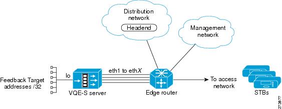
Types of Routes on a VQE-S
On the VQE-S, three types of routes are used:
•
•
•
The VQE-S also joins the multicast RTP streams from the distribution network. This interaction is between the VQE-S and the edge router. It takes place through the use of IGMP joins and does not involve routing with the local routing daemon on the VQE-S. This interaction is, in general, outside the scope of this discussion. Figure 2-1 shows the types of routes used on a VQE-S.
Figure 2-1 Routes Used on a VQE-S
Static Routes on a VQE-S
In Cisco VQE Release 3.1, OSPF routing was introduced on the VQE-S. Before this, the access routes and feedback target routes on a VQE-S were configured using static routes. Though static routes can still be chosen as the routing type, the use of static routes for the access routes and feedback target routes has some limitations.
For the access routes, use of static routes requires that the VQE-S be configured for the static routes to the access network. In contrast, with OSPF routing, the edge router advertises a default route to the access network through a routing protocol, allowing load balancing across the VQE-S interfaces and not requiring an extra configuration step.
For the feedback target routes, the use of static routes on the edge router means that repair services on the VQE-S for all feedback targets are assumed to always be available as long as the VQE-S interfaces are up. In some cases, although the interfaces are up, the VQE-S may not be able to handle requests for one or more feedback targets. The VQE-S itself can not add or withdraw the routes as services become available or unavailable for particular feedback targets. Another limitation of the use of static routes for feedback targets is that it requires the customer to take the extra step of configuring the edge router for feedback target addresses. In the worst case, this approach can require that each feedback target have a separate static route configured on the router if the feedback target addresses are not summarizable.
For information on configuring static-route parameters on a VQE-S, see the "Static Route Configuration: IP Address, Prefix Length, and Gateway Address" section.
For information on static route configuration on the edge router, see the "For Static Routes: Guidance for Configuring the Feedback Targets on the Attached Router" section.
OSPF Routing on a VQE-S
Starting with Release 3.1, Cisco VQE supports a dynamic routing feature, which uses OSPF routing to the access network from the VQE-S. The use of OSPF routing eliminates the limitations of static routing, see the "Static Routes on a VQE-S" section. Specifically, OSPF routing can be used on the VQE-S for the following:
•
•
Note
With dynamic routing, the feedback target routes can be advertised based on the actual capabilities of the VQE-S to process requests for services sent to those targets by adding and removing feedback target routes as needed.
On the VQE-S, the Quagga routing package provides the OSPF routing capability. The VQE Configuration Tool simplify the OSPF configuration on the VQE-S. After you enter values for OSPF configuration parameters, such as the OSPF area and router ID, these tools perform the configuration tasks for you. For information on configuring OSPF parameters for a VQE-S, see the "OSPF Configuration (VQE-S Host Only)" section.
For information on OSPF configuration on the edge router, see the "For OSPF Routing: Guidance for Configuring the Attached Router" section.
Using Dedicated or Shared Interfaces for VQE-S Ingest Traffic and for VQE-S Services Traffic
Some VQE deployments require that the CDE Ethernet interfaces or bond interfaces used for VQE-S ingest traffic (incoming multicast streams from the video sources) be separate from the interfaces used for VQE-S services traffic (Unicast Retransmission and RCC to the VQE-Cs on the STB). Dedicated Ethernet interfaces or dedicated bond interfaces allow the video distribution network to be separate from the access network.
The service provider can choose one of the following approaches when configuring the CDE Ethernet or bond interfaces:
•
–
–
The VQE Configuration Tool allow you to configure dedicated CDE Ethernet interfaces or bond interfaces for VQE-S ingest traffic and for VQE-S services traffic.
•
Note
Table 2-2 shows where to find information on the configuration parameters that are used for dedicated and shared interfaces.
Table 2-2 Where To Find Information on Parameters for Dedicated and Shared Interfaces
Dedicated interfaces for VQE-S ingest traffic
"Interfaces for VQE-S Ingest Traffic (VQE-S Host Only)" section
Dedicated interfaces for VQE-S services traffic
"Interfaces for VQE-S Services Traffic (VQE-S Host Only)" section
VQE-S traffic interfaces that handle VQE-S ingest traffic and VQE-S services traffic
"Interfaces for VQE-S Traffic (Ingest and Services) (VQE-S Host Only)" section
Routing Configuration for Dedicated Interfaces and Shared Interfaces
When a VQE deployment uses shared VQE-S traffic interfaces that handle both VQE-S ingest traffic and VQE-S services traffic, configuration of the CDE interfaces is as follows:
•
•
When a VQE deployment uses separate dedicated interfaces for VQE-S ingest traffic and for VQE-S services traffic, configuration of the CDE interfaces is as follows:
•
•
•
For information on the configuration parameters that are used for static routes, see the "Static Route Configuration: IP Address, Prefix Length, and Gateway Address" section.
For information on the configuration parameters that are used for OSPF routing, see the "OSPF Configuration (VQE-S Host Only)" section.
Configuring Static Routes
When a VQE deployment uses dedicated interfaces for VQE-S ingest traffic, the ingest interfaces use static routing to the distribution network where the video sources reside. To configure one or more static routes to the video distribution network, use the VCDB parameter network.route.static_route. Using the VQE Configuration Tool and their VCDB parameters, you specify the following for each ingest interface:
•
•
•
Caution
In following example from the VQE configuration Tool, two statics routes are configured. Ethernet interfaces eth1 and eth2 are configured as ingest interfaces. The IP address and prefix length of the distribution network is 192.0.0.0/8. The gateway IP address for the router interface directly attached to eth1 is 10.2.9.1. The gateway IP address for the router interface directly attached to eth2 is 10.2.10.1.
VQE Configuration Tool <Static Routing Parameters> Menu:1) Static Route(s):P) Go to Parent MenuR) Go to Root MenuEnter your choice: 1Add new static routes by entering destination subnet IP/Prefix and gateway IPpairs when prompted.To configure a default route, enter 0.0.0.0/0 as the destination subnet IP/Prefix.To specify a specific gateway interface (optional), add it to the end of thegateway IP, separated by ":" (e.g. "5.6.7.8:eth3).To complete the configuration, press <Enter> at the prompt without entering data.Enter the destination subnet in IP/Prefix format (e.g., 1.0.0.0/8): 192.0.0.0/8Enter the gateway IP address: 10.2.9.1Enter the destination subnet in IP/Prefix format (e.g., 1.0.0.0/8): 192.0.0.0/8Enter the gateway IP address: 10.2.10.1As the example shows, two static routes to the distribution network are configured; 192.0.0.0/8 via 10.2.9.1 (nexthop), and 192.0.0.0/8 via 10.2.10.1 (nexthop).
VQE Configuration Tool <Static Routing Parameters> Menu:1) Static Route(s): 1.1) 192.0.0.0/8 via 10.2.9.1 1.2) 192.0.0.0/8 via 10.2.10.1 P) Go to Parent MenuR) Go to Root MenuEnter your choice:Each static route has its own submenu. This allows an additional static route to be added without having to delete and recreate existing static routes. It also means that a single static route can be deleted or edited without effecting the other static routes.
As the example below shows, static route 192.0.0.0/8 via 10.2.10.1 can be deleted without having to delete static route 192.0.0.0/8 via 10.2.9.1. To restore the default value of a specific route, enter the number of the sub-menu for that specific value followed by the letter "d" and press Enter. For example:
VQE Configuration Tool <Static Routing Parameters> Menu:1) Static Route(s):1.1) 192.0.0.0/8 via 10.2.9.11.2) 192.0.0.0/8 via 10.2.10.1P) Go to Parent MenuR) Go to Root MenuTo reset a parameter to its factory default, enterits number choice followed by the letter `d' (e.g. 3d).Default values are displayed inside square brackets [].Enter your choice: 1.2dIn this example, when the Static Route(s) menu is displayed, the menu shows that the static route 192.0.0.0/8 via 10.2.10.1 has been deleted.
VQE Configuration Tool <Static Routing Parameters> Menu:1) Static Route(s):1.1) 192.0.0.0/8 via 10.2.9.1P) Go to Parent MenuR) Go to Root MenuInterface for a Management Network
Management traffic is blocked from non-management interfaces. The service provider must designate at least one CDE Ethernet interface or one bond interface as a management interface. Bond interfaces are configurable on the VQE-S hosts only. Multiple Ethernet or bond interfaces may be designated as management interfaces. The default value is all Ethernet interfaces on the VQE-S or VQE Tools server, regardless of their operational status.
Note
Table 2-3 displays the list of protocol port numbers that are blocked on non-management interfaces on VQE-S and VQE Tools Server. It also displays the standard type of management traffic associated with each of the ports.
Note
Table 2-3 Standard Management Protocol Ports Blocked on Non-Management Interfaces
22
SSH1
443
HTTPS2
444
HTTPS Push
161 and 162
SNMP3
21
FTP
1 SSH = Secure Shell.
2 HTTPS = Hypertext Transfer Protocol Secure.
3 SNMP = Simple Network Management Protocol.
VQE-S traffic (ingest and services), VQE-S ingest traffic or VQE-S services traffic may share the management interfaces. If your deployment requires that VQE-S traffic (ingest and services), VQE-S ingest traffic, or VQE-S services traffic be excluded from the CDE Ethernet interfaces or bond interfaces used for management traffic, do not include those CDE Ethernet interfaces or bond interfaces in the following VQE Configuration Tool parameters:
•
•
•
To set up one or more static routes to the management network, use the Static Route(s) parameter in the VQE Configuration Tool.
Load Balancing and Redundancy with Multiple VQE-S
When more than one VQE-S provides Unicast Retransmission and RCC or both services for a set of channels, the VQE-Ss and edge router can load balance the requests from the VQE-Cs on the STBs and provide failover protection if a VQE-S fails.
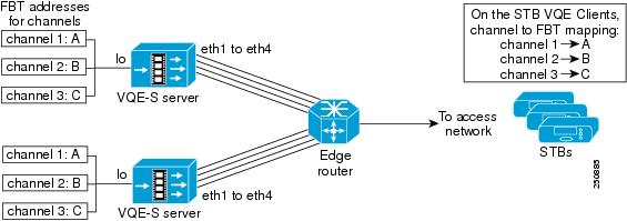
In the VCPT channel definition, each channel is associated with a unique feedback target (FBT) IP address. The VQE-Cs on the STBs use the FBT addresses to request Unicast Retransmission and RCC services for a particular channel. The FBT address is a unique IP anycast address that the VQE-S configures on its host Cisco CDE based on the channel information that is sent to it by VCPT or another channel-provisioning server. An anycast address is a unicast address that is assigned to multiple interfaces. With the appropriate routing topology, packets addressed to an anycast address are delivered to a single interface (in this case, the nearest interface of the VQE-S that is identified by the address).
The use of anycast IP addresses and Equal Cost Multipath (ECMP) routing allows multiple VQE-Ss in a single facility to balance the load among themselves and to provide failover protection in case of a server failure. As an example, Figure 2-2 shows a redundant pair of VQE-Ss, each providing Unicast Retransmission and RCC services for the same set of three channels. On both VQE-Ss, each channel is defined to have the same anycast IP address: A for channel 1, B for channel 2, and C for channel 3.
Figure 2-2 Redundant VQE-Ss for Service Failover and Load Balancing
When OSPF routing is configured on the VQE-S, the FBT routes are advertised from the VQE-S to the edge router. In this example, both VQE-Ss advertise FBT routes for a particular channel. If the services for that channel become unavailable on one VQE-S, that VQE-S withdraws the route. This allows the other VQE-S to take over services for that channel. If one VQE-S fails, the second VQE-S services the requests directed to the three feedback target addresses.
With OSPF routing and ECMP on the edge router, the router uses multi-interface load splitting on different interfaces with equal cost paths. ECMP provides load balancing of output traffic on the edge router interfaces that are attached to the VQE-S traffic interfaces on the CDE server. If three Ethernet interfaces on each of the two VQE-Ss were configured for VQE-S traffic, the edge router would load balance STB requests for VQE-S services over the six available Ethernet interfaces.
Configuring LACP Bonding on a VQE-S and VQE Tools Server
You can enable 803.ad LACP protocol for all bonds on the VQE-S and VQE-Tools Server. This is a global configuration for all bonds. To enable LACP bonding, use network.bond1 on the VQE-S and VQE-Tools Server:
The following two parameters support LACP bonding:
•
This can be set to either "lacp" or "balance-xor" (default).
•
This parameter can be either slow or fast. It is slow by default.
Restrictions
A service role (ingest, service, management) may only have a single VLAN assigned to it. For example, you may only assign one sub-interface of a given interface/bond to a given role.
LACP and LACP Rate are global configuration knobs. If LACP or LACP Rate are enabled, this applies to all bonds.
User Interface
The following example shows how to create a VLAN interface and enable LACP:
VQE Configuration Tool <Network Parameters> Menu:1) Routing Parameters2) Interface Parameters3) Bond Parameters4) VLAN ParametersR) Go to Root MenuEnter your choice: 3VQE Configuration Tool <Bond Parameters> Menu:1) Bond1 IP/Mask and members: []2) Bond2 IP/Mask and members: []3) Bond3 IP/Mask and members: []4) Bond4 IP/Mask and members: []5) Bond5 IP/Mask and members: []6) Enable 802.3ad LACP for Bonds: [false]7) Enable fast LACP rate: [false]P) Go to Parent MenuR) Go to Root MenuTo reset a parameter to its factory default value, enter its number choicefollowed by the letter 'd' (e.g. 3d). Default values are displayed insidesquare brackets [].Enter your choice: 6If you choose to enable LACP, all bonds will run in this mode instead of balance-xor.Enable 802.3ad LACP: y/[n] yVQE Configuration Tool <Bond Parameters> Menu:1) Bond1 IP/Mask and members: []2) Bond2 IP/Mask and members: []3) Bond3 IP/Mask and members: []4) Bond4 IP/Mask and members: []5) Bond5 IP/Mask and members: []6) Enable 802.3ad LACP for Bonds: true7) Enable fast LACP rate: [false]P) Go to Parent MenuR) Go to Root MenuTo reset a parameter to its factory default value, enter its number choicefollowed by the letter 'd' (e.g. 3d). Default values are displayed insidesquare brackets [].Enter your choice: 7Enable fast rate for LACP: y/[n] yVQE Configuration Tool <Bond Parameters> Menu:1) Bond1 IP/Mask and members: []2) Bond2 IP/Mask and members: []3) Bond3 IP/Mask and members: []4) Bond4 IP/Mask and members: []5) Bond5 IP/Mask and members: []6) Enable 802.3ad LACP for Bonds: true7) Enable fast LACP rate: trueP) Go to Parent MenuR) Go to Root MenuTo reset a parameter to its factory default value, enter its number choicefollowed by the letter 'd' (e.g. 3d). Default values are displayed insidesquare brackets [].Enter your choice:Configuring VLAN Support on a VQE-S and VQE-Tools Server
You can configure 802.1q VLAN sub-interfaces on all Ethernet and bond interfaces.
The following example shows how to configure VLAN support:
VQE Configuration Tool <Network Parameters> Menu:1) Routing Parameters2) Interface Parameters3) Bond Parameters4) VLAN ParametersR) Go to Root MenuEnter your choice: 4VQE Configuration Tool <802.1q Sub-Interface Parameters> Menu:1) Eth0 SubInterface VLAN tag IP/Mask:2) Eth1 SubInterface VLAN tag IP/Mask:3) Eth2 SubInterface VLAN tag IP/Mask:4) Eth3 SubInterface VLAN tag IP/Mask:5) Eth4 SubInterface VLAN tag IP/Mask:6) Eth5 SubInterface VLAN tag IP/Mask:7) Eth6 SubInterface VLAN tag IP/Mask:8) Eth7 SubInterface VLAN tag IP/Mask:9) Eth8 SubInterface VLAN tag IP/Mask:10) Eth9 SubInterface VLAN tag IP/Mask:11) Bond1 SubInterface VLAN tag IP/Mask:12) Bond2 SubInterface VLAN tag IP/Mask:13) Bond3 SubInterface VLAN tag IP/Mask:14) Bond4 SubInterface VLAN tag IP/Mask:15) Bond5 SubInterface VLAN tag IP/Mask:P) Go to Parent MenuR) Go to Root MenuTo reset a parameter to its factory default value, enter its number choicefollowed by the letter 'd' (e.g. 3d). Default values are displayed insidesquare brackets [].Enter your choice: 1Configure VLAN (802.1q) interfaces for eth0.Enter subinterface VLAN tag: 100Enter the IP/Prefix for eth0.100 (e.g. 1.2.3.4/8): 1.2.3.4/24Enter subinterface VLAN tag: 200Enter the IP/Prefix for eth0.200 (e.g. 1.2.3.4/8): 4.3.2.1/24Enter subinterface VLAN tag:VQE Configuration Tool <802.1q Sub-Interface Parameters> Menu:1) Eth0 SubInterface VLAN tag IP/Mask:1.1) 100 1.2.3.4/241.2) 200 4.3.2.1/242) Eth1 SubInterface VLAN tag IP/Mask:3) Eth2 SubInterface VLAN tag IP/Mask:4) Eth3 SubInterface VLAN tag IP/Mask:5) Eth4 SubInterface VLAN tag IP/Mask:6) Eth5 SubInterface VLAN tag IP/Mask:7) Eth6 SubInterface VLAN tag IP/Mask:8) Eth7 SubInterface VLAN tag IP/Mask:9) Eth8 SubInterface VLAN tag IP/Mask:10) Eth9 SubInterface VLAN tag IP/Mask:11) Bond1 SubInterface VLAN tag IP/Mask:12) Bond2 SubInterface VLAN tag IP/Mask:13) Bond3 SubInterface VLAN tag IP/Mask:14) Bond4 SubInterface VLAN tag IP/Mask:15) Bond5 SubInterface VLAN tag IP/Mask:P) Go to Parent MenuR) Go to Root MenuTo reset a parameter to its factory default value, enter its number choicefollowed by the letter 'd' (e.g. 3d). Default values are displayed insidesquare brackets [].Enter your choice:V
Using the VQE Configuration Tool
The CDE server has the VQE software preinstalled. The tool is available on the CDE that hosts VQE-S and on the CDE that hosts VQE Tools. We recommend that you use the VQE Configuration Tool rather than try to do the initial configuration manually because the tool simplifies your work and is known to produce correct results.
Before using the VQE Configuration Tool, do the following to understand how the tool works and what information you need to collect before powering on the VQE-S or VCPT server:
•
•
•
•
•
When it is started, the VQE Configuration Tool displays the following choices:
Please choose one of the following:1) I have all the information needed and want to proceed.2) I do not have all the information and want to shutdown the system.3) Skip configuration wizard and directly enter the system.If you select choice 1, the VQE Configuration Tool prompts you for configuration values.
If you select choice 2, the system is shutdown. The next time the system is started the VQE Configuration Tool is launched.
After you finish entering configuration values, the VQE Configuration Tool displays the Root Menu. The Root Menu allows you to view the values that you have specified and to change values that are not correct.
After using the VQE Configuration Tool, perform the verification tasks in the following sections:
•
•
Configuration Parameters
This section provides information on the configuration parameters present in the VQE Configuration Tool. Before using the VQE Configuration Tool, read the descriptions of the configuration parameters in this section.
Tip
In the explanations that follow, these conventions are used for the configuration parameters:
•
•
Note
Passwords for root and vqe User IDs
The password for root is set when the CDE boots normally for the first time (when you log in as root) and before the VQE Configuration Tool executes.
The vqe username is a predefined Linux user ID that the system administrator can use to log in to VQE-S AMT, VCDS AMT, and VCPT.
The root and vqe user passwords have the following requirements: A valid password should be a mix of uppercase and lowercase letters, digits, and other characters. You can use an eight-character long password with characters from at least three of these four classes, or a seven-character long password containing characters from all the classes. An uppercase letter that begins the password and a digit that ends it do not count toward the number of character classes used.
The password can be a passphrase. A passphrase should be at least three words with a combined total length of 12 to 40 characters.
Creating Linux users and maintaining password settings is the responsibility of the Cisco CDE system administrator. The default password settings for root, vqe, and Linux users are located in the /etc/pam.d/system-auth-ac file on the VQE-S and the VQE Tools server. For information on changing passwords for Linux and vqe users, see the Linux passwd man page at http://linux.die.net/man/1/passwd. For information on resetting the root password, see the "Resetting the Root Password on the VQE-S or VQE Tools Server" section. For more information on configuring password settings such as length, complexity, and ageing, for root, vqe, and Linux users, see the pam_passwdqc man page at http://linux.die.net/man/8/pam_passwdqc.
Hostname for the CDE
The hostname is used in multiple Linux configuration files. Allowed range is 3 to 200 characters.
Domain Name System (DNS) IP Addresses and a Search Domain
The IP addresses of one or more DNS servers and an optional search domain. Allowed range for the search domain is 3 to 200 characters.
System Timezone
The timezone and current system time that are used for this CDE. The VQE Configuration Tool prompts for the needed information.
NTP Server IP Addresses
The IP addresses of one or more external Network Time Protocol (NTP) servers.
Note
Current System Time
The current system time that are used for this CDE. The VQE Configuration Tool prompts for the needed information.
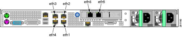
Ethernet Interface Configuration: IP Address and Prefix Length
For one or more of the Ethernet ports on the Cisco CDE, you specify an IP address and prefix length (for example, 1.2.3.4/32). The IP address and prefix length are not specified for any CDE Ethernet interface that is a member of a bond interface. The Ethernet ports are named eth1 to eth6 as shown in Figure 2-3.
Note
th4). These models did not have the Intel PRO/1000 PT Dual Port Server Adapter that provides the eth5 and eth6 ports.
•
•
•
Figure 2-3 Ethernet Port Numbering for Software Configuration
Bond Interface Configuration: IP Address and Prefix Length
On the VQE-S/VQE-Tool Server, you specify an IP address and prefix length (for example, 1.2.3.4/32) for one or more bond interfaces using the network.bondx.addr parameter where, depending on CDE model, bondx is bond1, bond2, or bond3. For each bond interface, you assign Ethernet interfaces to the bond interface using the network.bondx.member parameter where, depending on CDE model, bondx is bond1, bond2, or bond3. The Ethernet interfaces must not be members of an existing bond interface and do not have an IP address and prefix length assigned. On a VQE-S host, up to three bond interfaces may be configured and used for the Ethernet interfaces handling incoming multicast streams, outgoing VQE-S services, and management traffic. The number of bonds on a VQE-Tools Server is hardware dependent.
In the following example from the VQE Configuration Tool, the IP address and prefix length of bond1 is 11.2.15.2/24 and the Ethernet interfaces assigned to bond1 are eth3 and eth4.
VQE Configuration Tool <Interface Parameters> Menu:1) Eth1 Interface IP/Mask: 10.2.9.2/242) Eth2 Interface IP/Mask: 10.2.10.2/243) Eth3 Interface IP/Mask: [bond1]4) Eth4 Interface IP/Mask: [bond1]5) Eth5 Interface IP/Mask: []6) Eth6 Interface IP/Mask: []7) Bond1 IP/Mask and members: [11.2.15.2/24 eth3,eth4]8) Bond2 IP/Mask and members: []9) Bond3 IP/Mask and members: []10) Management Interface(s): eth1,eth2P) Go to Parent MenuR) Go to Root MenuEnter your choice:
Note
For more information on the restrictions that apply to the use of bond interfaces, see "Bond Interfaces on a VQE-S and VQE-Tools Server" section.
Static Route Configuration: IP Address, Prefix Length, and Gateway Address
If your deployment makes use of static routes to the management, distribution, or access network, the VQE Configuration Tool can configure static routes. Specify the following:
•
10.1.0.0/16
Note
•
•
Caution
As an example of gateway (next hop) IP address, if Ethernet interface eth4 were used for the target network, specify the IP address of the router interface that is directly attached to eth4.
On the VQE Tools server, proper route configuration is needed for external access to the VQE Tools server. You can use the static route created by this parameter to configure this access.
Note
On the VQE-S, multipath static routes can be configured for VQE-S traffic (ingest and services) or VQE-S services traffic. The VQE-S uses Equal Cost Multipath (ECMP) to load-balance its output traffic across CDE Ethernet interfaces or the physical Ethernet interfaces of a bond interface that are directly attached to the gateway router interfaces that are specified. If a default route (static route) is configured for each Ethernet interface that is available to VQE-S for Unicast Retransmissions, RCC, and other VQE-S traffic, ECMP load balances output traffic across all the CDE interfaces directly attached to the gateway router interfaces. Similarly, if a default route is configured for a bond interface, ECMP load balances output traffic across all the CDE physical interfaces assigned to the bond interface.
For more information on ECMP configuration, see the "Configuring Static Routes for VQE-S Traffic or VQE-S Services Traffic (VQE-S Host)" section.
SSL Certificate Options
Secure Sockets Layer (SSL) certificates must be created and deployed for VQE-S AMT, VCDS AMT, or VCPT to be accessed using HTTPS. The VQE Configuration Tool gives you three options for creating and deploying the certificates. For information on the three options and using the tool for creating and deploying SSL certificates, see the "Using the Cisco VQE Configuration Tool for SSL Certificates" section.
Trusted Provisioning Clients
The use of this VCDB parameter, system.iptables.trusted_provisioner, varies depending on the VQE-S type:
•
•
•
Note
This parameter is for enhanced communications security beyond HTTPS. The VQE-S or VQE Tools server is configured so that only trusted HTTPS clients (as specified in the Trusted Provisioning Client parameter) can send information to, respectively, the VQE-S or VQE Tools server using HTTPS.
Remote Syslog Hosts
On both the VQE-S and the VQE Tools server, VQE system messages are written to the file /var/log/vqe/vqe.log by default. In addition to logging system messages locally, you can send system messages by means of UDP to remote servers for centralized logging. This VCDB parameter, system.syslog.remote_server, is used to specify the IP addresses of the remote servers.
SNMP Read-Only Community String, Location, Contact, and Trap-Listener IP Addresses or Hostnames
If your deployment uses SNMP, specify the following:
•
•
•
•
For more information on SNMP for the CDE, see "SNMP MIBs."
Sending SNMP Traps
When SNMP is configured, the VQE-S and the VQE Tools server provide the capability to convert system messages to SNMP traps (syslog traps). To generate syslog traps, configure the following parameters:
•
•
The VQE-S provides the capability of sending a channel up trap when a channel becomes active and a channel down trap when a channel becomes inactive. Use the VCDB parameter system.snmp.channel_trap_enable (Enable Channel Up/Down traps menu) to enable or disable the generation of channel traps.
For information on configuring SNMP, see the "SNMP Read-Only Community String, Location, Contact, and Trap-Listener IP Addresses or Hostnames" section.
For more information on SNMP for the CDE, see "SNMP MIBs."
OSPF Configuration (VQE-S Host Only)
Table 2-4 describes the parameters that can be configured if OSPF is enabled. For detailed information on the OSPF parameters, see the following Quagga documentation:
http://www.quagga.net/docs/quagga.pdf
Table 2-4 OSPF Parameters
Enable OSPF
Specifies whether OSPF routing is enabled for VQE-S traffic (where shared interfaces to the access network are configured) or for VQE-S services traffic (where dedicated interfaces to the access network are configured).
Area Type
Type for the OSPF area that the VQE-S traffic interfaces and feedback target host addresses reside in. You can choose from either normal or nssa (Not So Stubby Area). If no value is specified, the default value is normal.
Area ID
Integer ID value for the OSPF area that the VQE-S Ethernet interfaces and feedback target addresses reside in. If no value is specified, the default value is 0. Allowed range is 0 to 4,294,967,295.
Router ID
IP address used as the router ID to uniquely identify the VQE-S in the OSPF network. The router ID must not be the same as the IP address of one of the CDE Ethernet interfaces because the router ID is added as an internal address to the loopback interface.
Enable MD5
Specifies whether MD51 authentication is enabled on the Ethernet interfaces used for VQE-S traffic. When MD5 authentication is enabled, specifying an MD5 key and MD5 key ID are required.
MD5 Key
If MD5 authentication is enabled, specifies a key (a string) that is configured for all Ethernet interfaces used for VQE-S traffic. When MD5 authentication is enabled, an MD5 key and MD5 key ID are required. Allowed length for the string is 1 to 16 characters.
MD5 Key ID
If MD5 authentication is enabled, specifies an MD5 key ID (an integer) that is used for all Ethernet interfaces used for VQE-S traffic. When MD5 authentication is enabled, an MD5 key and MD5 key ID are required. Allowed range of integer values is 1 to 255.
Hello Interval
Interval (in seconds) at which OSPF Hello packets are sent. This value must be the same for all interfaces running OSPF in the network. The hello interval is set for all VQE-S interfaces running OSPF. If no value is specified, the default value is 10. Allowed range is 1 to 65,535.
Dead Interval
OSPF dead interval (in seconds). The dead interval is the maximum amount of time allowed to receive a Hello packet from a neighbor before that neighbor is declared down. This value must be the same for all interfaces running OSPF in the network. The dead interval is set for all VQE-S interfaces running OSPF. If no value is specified, the default value is 40. Allowed range is 1 to 65,535.
1 MD5 = message digest 5.
For information about routing on the VQE-S host, see the "VQE-S and VQE-Tools Server: Routing and Interface Configuration Overview" section.
Interfaces for VQE-S Ingest Traffic (VQE-S Host Only)
If you choose to select dedicated interfaces for VQE-S ingest traffic, specify one or more CDE Ethernet interfaces or one or more bond interfaces that are used for ingest of multicast streams. Ethernet interfaces must not be members of an existing bond interface. Depending on CDE model, allowed choices of Ethernet interfaces are eth1 to eth6. Allowed bond interfaces are bond1 to bond3.
Note
When you choose to select dedicated interfaces for VQE-S ingest traffic and separate dedicated interfaces for VQE-S services traffic (see the next parameter), the following rules apply:
•
•
•
•
•
Interfaces for VQE-S Services Traffic (VQE-S Host Only)
If you choose to select a dedicated interface for VQE-S ingest traffic (the preceding parameter), you also must specify one or more CDE Ethernet interfaces or one or more bond interfaces that is used for VQE-S services—Unicast Retransmission and RCC traffic to downstream VQE-Cs on STBs. Ethernet interfaces must not be members of an existing bond interface. Depending on CDE model, allowed choices of Ethernet interfaces are eth1 to eth6. Allowed bond interfaces are bond1 to bond3.
Note
For the rules that apply when you choose to select a dedicated interface for VQE-S ingest traffic and interfaces for VQE-S services traffic, see the preceding "Interfaces for VQE-S Ingest Traffic (VQE-S Host Only)" section.
Interfaces for VQE-S Traffic (Ingest and Services) (VQE-S Host Only)
If you choose not to select dedicated interfaces for VQE-S ingest and services traffic, you specify the CDE Ethernet interfaces or one or more bond interfaces that are available for all VQE-S Traffic (ingest and services). Ethernet interfaces must not be members of an existing bond interface. The shared interfaces are used for ingest of multicast streams from upstream video sources and for VQE-S services (Unicast Retransmission and RCC traffic to downstream VQE-Cs on STBs). Ethernet and bond interfaces are different depending on the CDE model, refer to Table 2-7 for allowed choices for each model.
Note
Note
Interfaces for Management Traffic
At least one CDE Ethernet interface or one bond interface must be specified as the management interface. Ethernet interface must not be members of an existing bond interface. VQE-S traffic (ingest and services), VQE-S ingest traffic or VQE-S services traffic may share the management interfaces. Management traffic is blocked from non-management interfaces.
For the rules that apply when you specify management interfaces, see the "Interface for a Management Network" section.
VQE Configuration Tool Root Menu
After you finish specifying values for the configuration items, the VQE Configuration Tool displays the following menu:
VQE Configuration Tool Root Menu:1) System Parameters2) Network Parameters3) VQE-S ParametersS) Save and ExitA) Save/Apply and ExitE) Exit without savingEnter your choice:For information on this menu, see the "VQE Configuration Tool Root Menu" section.
When you have completed the configuration items, you choose S) Save/Apply and reboot system. The VQE Configuration Tool saves your configuration in the VCDB file, applies the VCDB values to the configuration files under /etc, and reboots the CDE system. Each time the VQE-S or VQE Tools host reboots, the services listed in Table 2-5 and Table 2-6 are started.
Note
Preconfiguration Worksheets
Before using the VQE Configuration Tool, complete the preconfiguration worksheets in Table 2-7 for a VQE-S host and Table 2-8 for a VQE Tools host before the first normal boot. The use of a VQE Tools server and VCPT is optional.
For information on the configuration items in Table 2-7 and Table 2-8, see the "Configuration Parameters" section.
VQE Configuration Tool Root Menu
After you have used the VQE Configuration Tool to specify values for the configuration items, the tool displays the Root Menu. The Root Menu allows you to view the values that you have specified and to change values that are not correct. The Root Menu on a VQE-S is as follows:
VQE Configuration Tool Root Menu:1) System Parameters2) Network Parameters3) VQE-S ParametersS) Save and ExitA) Save/Apply and ExitE) Exit without savingEnter your choice:This Root Menu and its behavior are similar to the standard VQE Configuration Tool Root Menu and behavior. The two differences are that the numbered choices 3 and 4 are only present in the VQE Configuration Tool, and the Save/Apply choice in the VQE Configuration Tool includes a reboot of the system.
Note
The Root Menu choices allow you to do the following:
•
•
To view and change parameter values, you can select choices 1, 2, and 3as many times as you wish.
Note
Table 2-9 provides more information about the choices on the Root Menu. You enter the number or letter for your choice.
Table 2-9 Root Menu Choices
1) System Parameters
Allows you to view the current system parameter values that you have set, and to change or set the system parameters values:
1) Hostname
2) DNS Server(s)
3) DNS Search Domain
4) Timezone
5) NTP Server(s)
6) Trusted Provisioning Client(s)
7) Remote Syslog Host(s)
8) SNMP ParametersR) Go to Root Menu
1) System Parameters > SNMP Parameters
1) SNMP RO Community String
2) SNMP System Location
3) SNMP System Contact
4) SNMP Trap Listener(s)
5) Enable Syslog Traps
6) Syslog Trap Priority
7) Enable Channel Up/Down TrapsP) Go to Parent Menu
R) Go to Root Menu
2) CDE110 Network Parameters > Interface Parameters
Allows you to view the current interface parameter values that you have set, and to change or set the interface parameters values:
1) Eth1 Interface IP/Mask
2) Eth2 Interface IP/Mask
3) Eth3 Interface IP/Mask
4) Eth4 Interface IP/Mask
5) Eth5 Interface IP/Mask
6) Eth6 Interface IP/Mask
7) Bond1 IP/Mask and members
8) Bond2 IP/Mask and members
9) Bond3 IP/Mask and members
10) Management Interface(s)P) Go to Parent Menu
R) Go to Root Menu
2) CDE250 Network Parameters > Interface Parameters
Allows you to view the current interface parameter values that you have set, and to change or set the interface parameters values:
1) Eth0 Interface IP/Mask
2) Eth1 Interface IP/Mask
3) Eth2 Interface IP/Mask
4) Eth3 Interface IP/Mask
5) Eth4 Interface IP/Mask
6) Eth5 Interface IP/Mask
7) Eth6 Interface IP/Mask
8) Eth7 Interface IP/Mask
9) Eth8 Interface IP/Mask
10) Eth9 Interface IP/Mask
11) Bond1 IP/Mask and members
12) Bond2 IP/Mask and members
13) Bond3 IP/Mask and members
14) Bond4 IP/Mask and members
15) Bond5 IP/Mask and members
16) Management Interface(s)2) Network Parameters > Routing Parameters > Static Routing Parameters
Allows you to view the current static routing parameter values that you have set, and change or set the static routing parameter value:
1) Static Route(s)
3) VQE-S Parameters
Allows you to view the current VQE-S parameter values that you have set, and to change or set the VQE-S parameters values:
1) Log Priority *
2) Excess Bandwidth Fraction *
3) Traffic (Ingest+Service) Interface(s)
4) Ingest Interface(s)
5) Service Interface(s)6) RTCP Exporter Parameters)
R) Go to Root Menu
* The VQE Configuration Tool does not allow you to set the values of these parameters in the set of parameters that were previously displayed. You can supply values at this point if you want or accept the defaults. For more information on these values, see the vcdb.conf.sample file and "VQE, System and Network Parameters."S) Save and Exit
Saves the changes you have made to the VCDB parameters and exits Configuration Tool. Any new parameter values are not applied to the configuration files under /etc.
A) Save/Apply and Exit
Saves the changes you have made to the VCDB parameters, applies any new parameter values to the configuration files under /etc, restarts services (as needed), and exits Configuration Tool..
E) Exit without saving
Exits Configuration Tool. Any changes you have made to the VCDB parameters are not saved.
On the VQE-S Host: Verifying the Status of the VQE and System Services
After the VQE Configuration Tool finishes and the CDE that hosts VQE-S reboots, it is recommended that you perform some quick checks to ensure that VQE and system services are running.
To verify the status of VQE services on the VQE-S host, follow these steps:
Step 1
Step 2
[root@system]# service sshd statussshd (pid 21165 21110 20595 20569 2777) is running...Step 3
[root@system]# service httpd statushttpd (pid 9665 9664 9663 9661 9660 9658 9657 9656 3978) is running...Step 4
[root@system]# service tomcat5 statusTomcat is running...Step 5
[root@system]# service snmpd statussnmpd (pid 2754) is running...Step 6
[root@system]# service snmpsa statusThe SNMP subagent is running.
Note
Step 7
[root@system]# service vqes_snmpsa statusvqes_subagent (pid 28603) is running...Step 8
[root@system]# service syslog_snmpsa statussyslog_subagent (pid 28472) is running...Step 9
[root@system]# service watchquagga statuswatchquagga (pid 2513) is running...[root@system]# service ospfd statusospfd (pid 7104) is running...[root@system]# service zebra statuszebra (pid 7072) is running...Step 10
[root@system]# service vqes statusprocess_monitor (pid 21853) is running...Step 11
[root@system]# ps -ef | grep vqeroot 710 1 0 Mar24 pts/7 00:00:00 /opt/vqes/bin/process_monitorvqes 723 710 0 Mar24 pts/7 00:00:00 stun_server --ss-uid 499 --ss-gid 499 --xmlrpc-port 8054 --log-level 6root 782 710 99 Mar24 pts/7 29-21:09:08 vqes_dp --group vqes --max-channels 500 --max-outstanding-rpcs 500 --max-pkts 150000 --log-level 6 --rtp-inactivity-tmo 300 --max-core-bw 850000000 --reserved-core-rcv-bw 100000000 --reserved-core-er-bw 120000000 --max-rai-gap 15vqes 855 710 0 Mar24 pts/7 00:00:00 vqes_cp --cp-uid 499 --cp-gid 499 --xmlrpc-port 8051 --cfg /etc/opt/vqes/vqe_channels.cfg --er-cache-time 3000 --rtp-hold-time 100 --max-channels 500 --max-outstanding-rpcs 500 --max-queued-rpcs 1000 --max-reserved-rpcs 32000 --max-clients 32000 --er-pkt-tb-rate 50000 --er-pkt-tb-depth 100 --er-blp-tb-rate 10000 --er-blp-tb-depth 100 --client-er-policing --client-er-tb-rate-ratio 5 --client-er-tb-depth 10000 --log-level 6 --rcc-mode conservative --igmp-join-variability 100 --max-client-bw 0 --max-idr-penalty 0 --rap-interval 2000 --excess-bw-fraction 20 --excess-bw-fraction-high-def 12 --high-def-min-bw 6000000 --buff-size-preroll-max 1500 --rcc-burst-delay-to-send 10 --rtp-dscp 0 --rtp-rcc-dscp -1 --rtcp-dscp 24 --overlap-loss 0 --intf-output-allocation 90 --max-rpr-stream-burst-msecs 30 --max-rpr-stream-burst-pkts 2 --unity-e-factor-interval 5 --min-client-excess-bw-fraction 0 --max-client-excess-bw-fraction 500[root@system]# ps -ef | grep mlbroot 2989 2965 0 09:17 pts/0 00:00:03 mlb --interface eth2,eth3,eth4 --xmlrpc-port 8052 --unicast-reservation 20 --poll-interval 1 --ssm --log-level 6In the preceding output, the VQE-S processes to check for are as follows:
•
•
•
•
•
Step 12
[root@system]# service ntpd statusntpd (pid 2790) is running...Step 13
https://ip_address_of_VQES_hostLog in using the vqe username and password. (Any valid Linux username and password can be used to log in to the VQE-S AMT).
If you click System in the left pane, the VQE-S AMT displays information on the VQE-S processes and channels. Figure 4-2 shows an example. Because at this point no channel information has been sent to the VQE-S, no channels are displayed.
Step 14
•
•
On the VQE Tools Host: Verifying the Status of the VQE and System Services
After the VQE Configuration Tool finishes and the CDE that hosts VQE Tools reboots, it is recommended that you perform some quick checks to ensure that VQE and system services are running.
To verify the status of VQE services on the VQE Tools host, perform the following steps:
Step 1
Step 2
[root@system]# service sshd statussshd (pid 21165 21110 20595 20569 2777) is running...Step 3
[root@system]# service httpd statushttpd (pid 9665 9664 9663 9661 9660 9658 9657 9656 3978) is running...Step 4
[root@system]# service tomcat5 statusTomcat is running...Step 5
[root@system]# service snmpd statussnmpd (pid 2754) is running...Step 6
[root@system]# service snmpsa statusThe SNMP subagent is running.Step 7
[root@system]# service vcds_snmpsa statusvqes_subagent (pid 28603) is running...Step 8
[root@system]# service syslog_snmpsa statussyslog_subagent (pid 28472) is running...Step 9
[root@system]# service ntpd statusntpd (pid 2790) is running...Step 10
https://ip_address_of_VQE_tools_hostLog in with a Linux username and password.
If you are able to log in successfully, VCPT is running correctly.
Step 11
https://ip_address_of_VQE_tools_host/vcds-amtLog in using the VQE username and password. (Any valid Linux username and password can be used to log in to the VCDS AMT.)
If you click System in the left pane, the VCDS Status window displays information on the VCDS processes. Figure 5-2 shows an example.
Step 12
•
•
Configuring the VQE-S RTCP Exporter
VQE-S RTCP Exporter is the VQE-S software component responsible for sending the RTCP reports to an external device that hosts the video-quality monitoring (VQM) application. Use of RTCP Exporter is optional.
Starting with Cisco VQE 3.7 Release, VQE-S supports exporting RTCP reports to one or at most two VQMs at a time.Also, in this release VQE-S RTCP Exporter can be configured either by vqe_cfgtool or by manually editing vcdb.conf file.
To monitor the RTCP Exporter, use the VQE-S AMT. This tool displays RTCP Exporter configuration details and status as well as counters of exported packets. The VQE-S AMT can also be used to enable or disable RTCP Exporter debugging.
To troubleshoot the RTCP Exporter, examine the Exporter syslog messages, which are sent to the VQE-S log file (/var/log/vqe/vqe.log). If more detailed troubleshooting is needed, enable RTCP Exporter debugging using VQE-S AMT and examine the debug messages, which are also sent to the VQE-S log file.
Starting with Cisco VQE 3.7 release, RTCP exporter can be configured/enabled via the following two methods:
•
•
Configuring VQE-S RTCP Exporter via manually editing the VCDB File
To configure and enable the RTCP Exporter on the Cisco CDE that hosts VQE-S, follow these steps:
Step 1
[root@system]# vqe_cfgtoolStep 2
For information on manually editing the vcdb.conf file, see the "Manually Editing the VCDB File" section.
Step 3
RTCP Exporter remains disabled unless both VQM Host IP Address and Port are configured and are valid.
By default, the vcdb.conf file contains no RTCP Exporter parameters and RTCP Exporter is disabled.
Step 4
[root@system]# vqe_cfgtool -applyFor more information on the vqe_cfgtool command and the -apply option, see the "Using the VQE Configuration Tool Command-Line Options" section.
Note
Configuring VQE-S RTCP Exporter via VQE Configuration Tool
You can also configure VQE-S RTCP Exporter via VQE Configuration Tool.
The following example shows how to configure VQE-S RTCP Exporter:
VQE Configuration Tool <VQE-S Parameters> Menu:1) Log Priority: 6 2) Excess Bandwidth Fraction: [20]% 3) Traffic (Ingest+Service) Interface(s): eth2,eth3,eth4,eth5,eth6 4) Ingest Interface(s): [] 5) Service Interface(s): [] 6) RTCP Exporter Parameters: R) Go to Root MenuTo reset a parameter to its factory default value, enter its number choice followed by the letter 'd' (e.g. 3d). Default values are displayed inside square brackets []. Enter your choice:6 VQE Configuration Tool <RTCP Exporter Parameters> Menu:1) Enable Exporter: [false] 2) Enable NACK Filter: [false] 3) VQM Parameters: P) Go to Parent Menu R) Go to Root MenuTo reset a parameter to its factory default value, enter its number choice followed by the letter 'd' (e.g. 3d). Default values are displayed inside square brackets []. Enter your choice: 1 Enable Exporter?: y/[n] y VQE Configuration Tool <RTCP Exporter Parameters> Menu:1) Enable Exporter: true 2) Enable NACK Filter: [false] 3) VQM Parameters: P) Go to Parent Menu R) Go to Root MenuTo reset a parameter to its factory default value, enter its number choice followed by the letter 'd' (e.g. 3d). Default values are displayed inside square brackets []. Enter your choice: 2 Enable NACK Filter?: y/[n] y VQE Configuration Tool <RTCP Exporter Parameters> Menu:1) Enable Exporter: true 2) Enable NACK Filter: true 3) VQM Parameters: P) Go to Parent Menu R) Go to Root MenuTo reset a parameter to its factory default value, enter its number choice followed by the letter 'd' (e.g. 3d). Default values are displayed inside square brackets [].Enter your choice: 3 Configure the VQM host(s) for RTCP Exporter reports. VQM parameter must be added as a colon separated field "host:port", where host is the IP address or host name of the VQM, and "port" is the port number. For multiple VQMs, enter one VQM parameter per line. Maximum number of VQMs supported is 2. To complete the configuration, press <Enter> at the prompt without entering data. Usage example: 127.0.0.1:3000 Enter VQM information as "host:port":123.0.0.98:4000 Enter VQM information as "host:port":134.98.78.67:6000 VQE Configuration Tool <RTCP Exporter Parameters> Menu:1) Enable Exporter: true 2) Enable NACK Filter: true 3) VQM Parameters: 3.1) 123.0.0.98:4000 3.2) 134.98.78.67:6000 P) Go to Parent Menu R) Go to Root MenuTo reset a parameter to its factory default value, enter its number choice followed by the letter 'd' (e.g. 3d). Default values are displayed inside square brackets []. Enter your choice: r VQE Configuration Tool Root Menu:1) System Parameters 2) Network Parameters 3) VQE-S Parameters S) Save and Exit A) Save/Apply and Exit E) Exit without saving Enter your choice:A vcdb.conf is successfully updated. Applying this configuration will cause the following service interruptions: Restart of VQE services (process_monitor) for configuration change. Do you want to proceed and apply these changes?: y/[n] y
Configuring the Other Parameters for the VQE-S Host
The set of parameters for the VQE-S host includes many parameters that are not configurable with the VQE Configuration Tool. Many additional parameters are used, for example, to make adjustments to the VQE-S software facilities that perform Unicast Retransmission and RCC.
Read the following to get information on these additional parameters:
•
•
•
Configuring the Edge Router for VQE-S
This section provides some guidance on configuring the edge router that is directly attached to the VQE-S host. Depending on whether OSPF routing or static routes are used on the VQE-S host, refer to one of the following sections:
•
•
•
For Bond Interfaces: Guidance for Configuring Bond Interface on the Attached Router
This section provides guidance on manually configuring bond interfaces (EtherChannels) on the edge router that is directly attached to the VQE-S. This section assumes that the attached router is a Cisco 7600 running Cisco IOS software. A bond interface is referred to by the terms EtherChannel and port-channel group on a Cisco 7600 router. A port-channel is used to group up to four Ethernet interfaces. It aggregates the bandwidth of the underlying Ethernet interfaces. All Ethernet interfaces must have the same speed.
To configure a port-channel on the Cisco 7600 router, do the following:
Step 1
interface port-channel channel-number
The channel-number is the number assigned to this port-channel interface. As each channel can consist of up to four Ethernet interfaces, the valid range is 1 to 4.
Step 2
ip address ip-address mask
Step 3
interface fastethernet number
Step 4
channel-group number mode ON
The EtherChannel has been statically configured without running dynamic protocols, such as Link Aggregation Control Protocol (LACP) or Port Aggregation Protocol (PAgP).
In the following example, the port-channel 1 is assigned an IP address and network mask. Next, the Ethernet port 1 and Ethernet port 2 on module 8 are assigned to port-channel 1. Finally, the EtherChannel is enabled.
7600# configure terminal7600(config)# interface port-channel 17600(config-if)# ip address 1.1.1.10 255.255.255.07600(config-if)# exit7600(config)# interface GigabitEthernet 8/17600(config-if)# channel-group 1 mode on7600(config-if)# exit7600(config)# interface GigabitEthernet 8/27600(config-if)# channel-group 1 mode on7600(config-if)#To display EtherChannel information, use the following command:
show etherchannel [channel-group] {port-channel | brief | detail | summary | port | load-balance | protocol}
The following example displays a summary of information for etherchannel 2.
7600# show etherchannel 2 briefGroup: 2----------Group state = L2Ports: 4 Maxports = 8Port-channels: 1 Max Port-channels = 1Protocol: - (Mode ON)7600#For more information on the commands used to configure EtherChannels on a Cisco 7600 router, see the Cisco 7600 Series Router Cisco IOS Command Reference Guide.
For OSPF Routing: Guidance for Configuring the Attached Router
If OSPF routing is enabled for VQE-S traffic or VQE-S services traffic, the following sections provide guidance on configuring the edge router that is directly attached to VQE-S:
•
For detailed information on OSPF and the Cisco IOS commands used to configure the routing protocol, see the OSPF resources at:
http://www.cisco.com/en/US/tech/tk365/tk480/tsd_technology_support_sub-protocol_home.html
Note
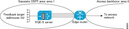
VQE-S in a Separate OSPF Area
The VQE-S can be configured to be in a separate OSPF area by specifying the VCDB parameter network.ospf.area to be a non-zero value. With the VQE Configuration Tool, this separate area with the VQE-S can be defined as a normal area or a Not So Stubby Area. Figure 2-4 shows the VQE-S in a separate OSPF area: area 1.
Figure 2-4 VQE-S in a Separate OSPF Area
When the VQE-S is configured in a separate OSPF area, these guidelines for configuring the directly attached edge router apply:
•
•
With a NSSA, the edge router generates a default route to the access network and advertises the default route in the NSSA (in Figure 2-4, area 1). This default-route mechanism reduces the size of the VQE-S routing table.
To configure the NSSA and to configure the edge router to advertise the default route in the NSSA, issue the following Cisco IOS commands on the edge router:
router ospf process-id
area area-id nssa no-summaryWhen no-summary is specified with area nssa, the edge router advertises the default route in the NSSA but does not inject summary routes into the area.
VQE-S in Area 0
When the VQE-S is configured within OSPF area 0 (that is, when the network.ospf.area VCDB parameter value is zero, the default), these guidelines for configuring the directly attached edge router apply:
•
•
General Guidelines
The following are general edge router configuration guidelines:
•
•
interface name
ip ospf hello-interval 1
ip ospf dead-interval 4•
•
•
router ospf process-id
maximum-paths maximum-paths•
•
For Static Routes: Guidance for Configuring the Feedback Targets on the Attached Router
When channels are configured with a channel-provisioning tool such as VCPT, it is required that you specify a unique feedback target (FBT) address for each channel. If static routes are used for VQE-S traffic (ingest and services) or VQE-S services traffic, the router that is directly attached to the VQE-S host must have a static route configured for the FBT address so that the router can reach the target. If the FBT addresses are allocated within a contiguous address range, this configuration piece can be done with a single aggregated route.
For example, if the FBT addresses for the channels are assigned to be 8.86.1.1, 8.86.1.2, 8.86.1.3, ..., 8.86.1.250, then the single static route 8.86.1.0/24 configured on the directly attached router allows any of these FBT addresses to be reached. The commands on the router for the FBT addresses would be as follows:
configure terminalip route 8.86.1.0 255.255.255.0 10.2.9.2ip route 8.86.1.0 255.255.255.0 10.2.10.2ip route 8.86.1.0 255.255.255.0 10.2.11.2ip route 8.86.1.0 255.255.255.0 10.2.12.2For the preceding configuration example, the IP addresses 10.2.9.2, 10.2.10.2, 10.2.11.2, and 10.2.12.2 have been assigned to the Ethernet interfaces on the VQE-S host. See Figure D-3. These Ethernet interfaces are used for VQE-S traffic, including Unicast Retransmission and RCC traffic.