Feedback
Table Of Contents
Getting Started with CDS Video Navigator
Configuring Terminal Emulation Software
Connecting Cables to the CDE110
Configuring the Ethernet Interfaces
Preparing to Configure Poster Art Server
Configuring the Apache Web Server
Starting Video Navigator and Verifying System Status
Configuring for Resiliency with Cisco ACE (Optional)
Information on CDE110 Hardware
Getting Started with CDS Video Navigator
This chapter explains how to perform the initial configuration tasks needed to get Cisco Content Delivery System (CDS) Video Navigator and Cisco CDS Poster Art Server running. (Both applications are preinstalled together.) Read the following sections and perform the initial configuration tasks in this order:
1.
Configuring Terminal Emulation Software
2.
3.
4.
5.
6.
7.
Where optional support for resiliency by means of the Cisco Application Control Engine (ACE) module is required, see Configuring for Resiliency with Cisco ACE (Optional), for basic configuration steps. In addition, Information on CDE110 Hardware contains some notes on the hardware components and configuration used with Video Navigator.
This chapter assumes that the Cisco CDE110 hardware has been installed as described in the Cisco Content Delivery Engine 110 Hardware Installation Guide, including connecting cables and connecting power.
Note
Configuring Terminal Emulation Software
The RJ-45 serial ports on the Cisco CDE110 front and back panels can be used for administrative access to the CDE110 through a terminal server. Terminal emulation software must be configured as follows:
•
•
•
•
•
Connecting Cables to the CDE110
The following cable connections are used on the CDE110:
•
–
–
•
•
Note
•
For the location of connectors on the CDE110 front and back panels, see the Cisco Content Delivery Engine 110 Hardware Installation Guide.
Configuring the Ethernet Interfaces
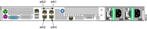
This section explains how to configure an Ethernet interface on the CDE110. For software configuration, the RJ-45 Ethernet ports on the CDE110 back panel are specified as eth0, eth1, eth2, and eth3, as shown in Figure 2-1.
Figure 2-1 Port Numbering for Software Configuration
Note
Figure 2-2 shows the example IP addresses used in the configuration examples in this section.
•
•
Figure 2-2 Example IP Addresses for Video Navigator Configuration
To configure the CDE110 Ethernet interfaces for Video Navigator, do the following:
Step 1
The operating system boots.
Step 2
Note
Step 3
•
•
IPADDR=ip_address_of this_system_eth#•
NETMASK=netmask_for_eth#_networkFor example, for the eth1 interface, the /etc/sysconfig/network-scripts/ifcfg-eth1 file would include the following after the modifications:
ONBOOT=yesIPADDR=10.2.10.2NETMASK=255.255.255.0Step 4
[root@system]# ifup eth1Step 5
•
[root@system]# ifconfig eth1eth1 Link encap:Ethernet HWaddr 00:0E:0C:C6:F3:0Finet addr:10.2.10.2 Bcast:10.2.10.255 Mask:255.255.255.0inet6 addr: fe80::20e:cff:fec6:f30f/64 Scope:LinkUP BROADCAST RUNNING MULTICAST MTU:1500 Metric:1RX packets:3 errors:0 dropped:0 overruns:0 frame:0TX packets:36 errors:0 dropped:0 overruns:0 carrier:0collisions:0 txqueuelen:1000RX bytes:192 (192.0 b) TX bytes:2700 (2.6 KiB)Base address:0x3000 Memory:b8800000-b8820000•
[root@system]# ip link show eth1eth1: <BROADCAST,MULTICAST,UP,LOWER_UP> mtu 1500 qdisc pfifo_fast qlen 1000link/ether 00:0e:0c:c6:e4:fe brd ff:ff:ff:ff:ff:ff•
[root@system]# ping device_IP_addressStep 6
10.2.9.2 starfire-iptvStep 7
Note
Step 8
HOSTNAME=starfire-iptvStep 9
Note
Step 10
[root@system]# init 6The operating system restarts.
Configuring Video Navigator
Video Navigator is a web application that requires minimal configuration.
Note
To configure Video Navigator, do the following:
Step 1
Step 2
$ cd /home/isa/MIDAS/configStep 3
BackofficeVendor=EventISBackofficeUrl=http://192.124.21.22/Step 4
Preparing to Configure Poster Art Server
Poster Art Server is configured by means of an XML file that must first be uncompressed.
Do the following to uncompress the Poster Art Server configuration file.
Step 1
cd /home/isa/MIDAS/webapps/Step 2
jar xvf paserver.war
Note
Step 3
For details, see Chapter 3, "Understanding and Using the Cisco CDS Poster Art Server," and proceed to the "Configuring Poster Art Server" section on page 3-8.
Configuring the Apache Web Server
You must configure the Apache web server to work with multiple IP addresses. Typically, two CDE110 Ethernet interfaces are configured with IP addresses. One Ethernet interface is for the STB client-facing VLAN, and the other Ethernet interface is for the management- and VBO-facing VLAN.
Do the following to configure the Apache web server:
Step 1
Step 2
# cd /usr/local/apache2/binStep 3
# ./apachectl stopStep 4
# cd /usr/local/apache2/confStep 5
a.
# Listen: Allows you to bind Apache to specific IP addresses and/or# ports, instead of the default. See also the <VirtualHost># directive.## Change this to Listen on specific IP addresses as shown below to# prevent Apache from glomming onto all bound IP addresses.#Listen 80b.
Listen xxx.xx.xx.xxx:80Listen yyy.yy.yy.yyy:80In the preceding, xxx.xx.xx.xxx and yyy.yy.yy.yyy are the IP addresses that you configured for the two CDE110 Ethernet interfaces.
c.
Step 6
# cd /usr/local/apache2/binStep 7
# ./apachectl start
Starting Video Navigator and Verifying System Status
The following system services are started automatically each time the CDE110 is powered on:
•
•
•
This section shows you how to do the following:
1.
2.
3.
Note
Do the following to start Video Navigator and verify that the needed processes are running:
Step 1
su - isaStep 2
$ start_midasMIDAS not running ....... starting MIDASStep 3
$ check_midasMIDAS (2.1.X.X) is runningIf Video Navigator is not running, the output is as follows:
MIDAS is not running
Step 4
$ cd /home/isa/MIDAS_IntegrationTest$ clientinterfacetestThe clientinterfacetest script does not verify the connection from Video Navigator to the STB. It verifies that the client-facing web services interface of Video Navigator is working correctly.
If the test is successful, the output is as follows:
***************************************************
Start testing liveness of MIDAS client interface.
***************************************************
output = <html><body><h1>Welcome to MIDAS Server</h1></body></html>
Test successfulIf the test is not successful, the output is as follows:
***************************************************
Start testing liveness of MIDAS client interface.
***************************************************
Method failed: HTTP/1.1 503 Service Temporarily Unavailable
Test unsuccessful
Step 5
Step 6
# ps -ef | grep sshdroot 2835 1 0 Jul18 ? 00:00:00 /usr/sbin/sshdStep 7
# ps -ef | grep httpdroot 2880 1 0 Jul18 ? 00:00:00 /usr/sbin/httpdapache 4881 2880 0 04:03 ? 00:00:00 /usr/sbin/httpdapache 4882 2880 0 04:03 ? 00:00:00 /usr/sbin/httpdapache 4883 2880 0 04:03 ? 00:00:00 /usr/sbin/httpdapache 4884 2880 0 04:03 ? 00:00:00 /usr/sbin/httpdapache 4885 2880 0 04:03 ? 00:00:00 /usr/sbin/httpdapache 4886 2880 0 04:03 ? 00:00:00 /usr/sbin/httpdapache 4887 2880 0 04:03 ? 00:00:00 /usr/sbin/httpdapache 4888 2880 0 04:03 ? 00:00:00 /usr/sbin/httpdStep 8
# ps -ef | grep tomcat5root 2915 1 0 Jul18 ? 00:00:11 /usr/java/default/bin/java -Djava.util.logging.manager=org.apache.juli.ClassLoaderLogManager -Djava.util.logging.config.file=/usr/share/tomcat5/conf/logging.properties -Djava.endorsed.dirs=/usr/share/tomcat5/common/endorsed -classpath :/usr/share/tomcat5/bin/bootstrap.jar:/usr/share/tomcat5/bin/commons-logging-api.jar -Dcatalina.base=/usr/share/tomcat5 -Dcatalina.home=/usr/share/tomcat5 -Djava.io.tmpdir=/usr/share/tomcat5/temp org.apache.catalina.startup.Bootstrap startStep 9
•
•
Step 10
# cd /etcStep 11
a.
#su - isa -c "cd /home/isa/MIDAS; ./run_midas >& /home/isa/MIDAS/midas_log&"b.
Configuring for Resiliency with Cisco ACE (Optional)
Video Navigator basically takes HTTP requests from the STB. To provide resiliency, the Cisco Application Control Engine (ACE) module is used to connect to two or more Video Navigator servers. The basic configuration is as follows:
1.
2.
3.
4.
5.
6.
7.
The ACE module supports two kinds of aliveness check, port aliveness and application aliveness, as follows:
•
•
Because subscriber-specific data is queried each time an STB browses the VoD catalog, it is possible that one Video Navigator server in the farm has subscriber-specific data that the others do not.
Caution
Note
Information on CDE110 Hardware
For information about the Cisco Content Delivery Engine 110, see the Cisco Content Delivery Engine 110 Hardware Installation Guide at the following URL:
http://www.cisco.com/en/US/docs/video/cds/cde/cde110/installation/guide/cde110_install.html