-
Cisco Prime Optical User Guide, 9.8
-
Preface
-
Chapter 1: Introduction
-
Chapter 2: Basic Concepts
-
Chapter 3: Building the Network
-
Chapter 4: Maintaining an Efficient Network
-
Chapter 5: Configuring Hardware
-
Chapter 6: Provisioning Cards
-
Chapter 7: Provisioning Services and Connections
-
Chapter 8: Managing Security
-
Chapter 9: Managing Faults
-
Chapter 10: Managing Performance
-
Chapter 11: Managing Inventory
-
Chapter 12: Managing Southbound and Northbound Interfaces
-
Chapter 13: Configuring MPLS-TP Using the CPT System
-
Appendix A: Icons and Menus Displayed in Prime Optical
-
Appendix B: NE Explorer Information
-
Appendix C: Slot Property Information--Common, DWDM, Electrical, and Ethernet Cards
-
Appendix D: Slot Property Information—FC_MR-4, FMEC, Multirate, and Optical Cards
-
Appendix E: Performance Data
-
Appendix F: Error Messages
-
Appendix G: Troubleshooting
-
Appendix H: ML Provisioning Methodology
-
Glossary
-
 Feedback
Table Of Contents
SNMPv1 and SNMPv2 Trap Destination Setup
Point-to-Point Base Card Configuration
Packet over SONET, Ethernet, and Shared Packet Ring Port Provisioning
Flow Control (Send) Provisioning
Creating or Modifying a Port Channel
Creating or Modifying a Port Channel Member
Deleting a Port Channel Member
IEEE 802.17 RPR Base Card Configuration
Protection Support on ML-Series Cards
Using the Quality of Service Policy Template
Configuring Best-Effort Class Map
Configuring Advanced Class Map
Bandwidth Data Service Provisioning
IP Service-Level Agreement on ML-Series Cards
Enabling or Disabling Rapid Spanning Tree Protocol
Enabling or Disabling Cisco Discovery Protocol
Modifying Layer 2 Service Drops
Enable L2 Service Command Enhancement
ML Provisioning Methodology
Prime Optical supports data service provisioning over ML-series cards. Data service provisioning consists of provisioning the Layer 2 topology using optical circuits, and then provisioning the Layer 2 service on top of the Layer 2 topology.
Alarm notification and performance monitoring features on data cards (ML-series cards) are SNMP-based. To allow Prime Optical to support alarm and event notification and performance monitoring on data cards, the SNMP trap forwarding mechanism must be set up on each node of the data card.
This appendix describes the methodology that Cisco Prime Optical 9.8 uses to provision ML-series cards and also provides the set of Cisco IOS commands issued by Prime Optical during Layer 2 topology and Layer 2 service provisioning, including provisioning of interface ports for ML data cards. The syntax used for the commands must be respected for services provisioned directly using Cisco IOS so that Prime Optical recognizes the provisioned services.
This appendix includes the following sections:
•
SNMPv1 and SNMPv2 Trap Destination Setup
•
•
•
•
•
•
•
•
•
Overview
A Layer 2 topology can be a point-to-point optical circuit; Resilient Packet Ring (RPR) or an IEEE802.17 RPR consisting of a chain of optical circuits; or hub and spoke, consisting of multiple optical circuits connected in a hub-and-spoke fashion. Hub-and-spoke topologies are supported as multiple point-to-point topologies.
For a point-to-point topology, the following card combinations are supported:
•
•
•
•
•
When deployed as hub and spoke, the ML-series card can be placed at the spoke locations, with the G-series card providing an extension of the traffic to a Cisco 7600, which forms the hub of the architecture. This arrangement provides a cost-effective way to interface to the Cisco 7600. Alternatively, the ML-series card can be deployed at both the hub and the spoke sites.
When deployed as an RPR or DOT17RPR, all sites contain ML-series cards (ML-1000-2, ML-100T-12, or ML-100T-8). A minimum of two ML-series cards is required to configure an RPR.
You use Prime Optical to provision ML-series cards by opening a Telnet session to each card. Before doing this, provision each ML-series card and create a password configuration that allows you to use Prime Optical to log in. For this purpose, a barebone file is provided on the Prime Optical server disk (Disk 1).
A different file is provided for the following cards:
•
•
•
Note
•
Caution
Reset the ML-series card after loading the barebone file and wait for 5 minutes before provisioning topologies and services. The login and password are reported in the Control Panel window. You can create other profiles on ML-series cards by using the IOS Users table (available under Administration > CTC-Based NEs > IOS Users Table).
After entering command-line interface (CLI) commands through the Telnet session, Prime Optical issues a write or copy run start command to write the Cisco IOS configuration file to the Timing, Communications and Control (TCC) flash. When the Cisco IOS configuration file is written to the TCC flash (by Prime Optical or by another user), Prime Optical is notified. To verify that Prime Optical has been notified, enter the write command after any CLI change.
Prime Optical provides a GUI wizard to facilitate provisioning of L2 topologies and related L1 circuits. For details, see Provisioning Data Services. Create an RPR or point-to-point topology involving some of the ML-series cards in the network. Based on the L2 topology circuit type and size that you specify, Prime Optical creates related L1 circuits and installs a base card configuration on each ML-series card in the RPR ring.
The Create Layer 2 Service wizard guides you through the VLAN creation. There is no CLI to create a circuit VLAN. An RPR supports from 1 to 4095 VLANs, and these VLANs are enabled at all times. All that is required is to configure the endpoint to connect a ring VLAN to a port VLAN that is either an Ethernet port or a port channel. Only ML devices are supported on an RPR.
Point-to-point topologies are supported for ML-ML, ML-G1000, ML-OC, and ML-CE cards. Point-to-point topology creation is similar to RPR creation in that based on the L2 topology circuit type and size that you specify, Prime Optical creates related L1 circuits and installs a base card configuration on each ML-series card in the point-to-point topology.
Note
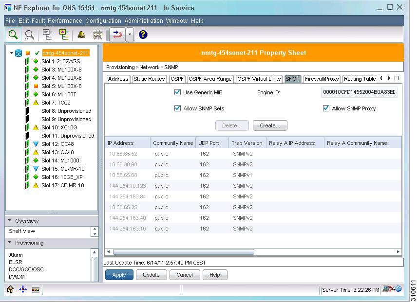
SNMPv1 and SNMPv2 Trap Destination Setup
For the cards to have full Prime Optical support, the SNMP trap destination must be set up for each node where there is a data card inserted:
•
•
•
•
Figure H-1 NE Explorer—SNMPv1 and SNMPv2 Trap Destination Setup
The following table lists the possible SNMP configurations.
When setting up an SNMPv1 or SNMPv2 trap destination:
1.
2.
3.
4.
SNMPv3 Configuration
Prime Optical supports SNMPv3 on CTC-based release 9.8 NEs. (SNMPv3 is not supported on ONS 15305, ONS 15305 CTC, or ONS 15327 NEs.)
As is the case for SNMPv1 and SNMPv2, to support SNMPv3, NEs with ML-series cards must have a valid SNMP configuration to guarantee correct initialization and management of Layer 2 parameters. If the SNMP configuration is invalid, the Audit Log records a resynchronization failure.
Configuring SNMPv3 is more complex than configuring SNMPv1 or SNMPv2, because the following tables must be filled in:
•
•
•
•
•
•
•
For details about configuring SNMPv3, see Managing SNMPv3—CTC-Based Release 9.6 NEs.
CLI Configuration Details
Note the following CLI conventions:
•
[notes]
•
[match any]
•
parameter
•
{parameter_1 | parameter_2 | parameter_3}
Base Card Configuration
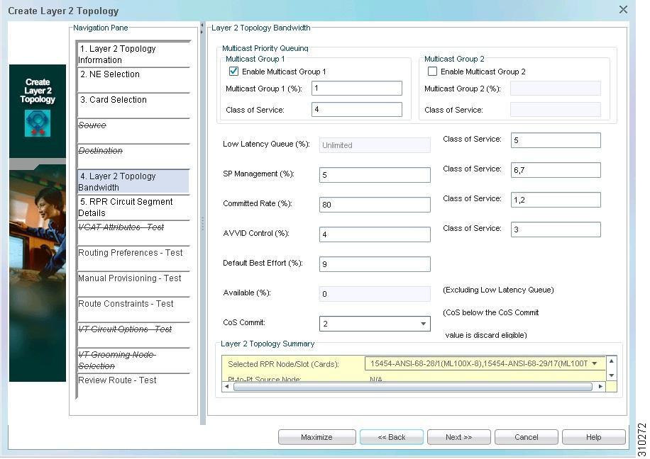
The base card configuration is a set of commands entered during the L2 topology creation. The parameters are defined in the Create Layer 2 Topology wizard > Layer 2 Topology Bandwidth pane (see Figure H-2).
Note
Figure H-2 Create Layer 2 Topology Wizard
RPR Base Card Configuration
To create an RPR topology, you must apply the base card configuration to all ML-series cards in the RPR. The ring is not functional and is reported as L2 Not Ready until the base card configuration is applied to all cards. You can select an L2 Not Ready RPR in the L2 Topology table and enable the L2 service provisioning by choosing Configuration > Enable L2 Service.
Caution
Prime Optical defines the unique card number within the ring. The actual range is from 1 to 251 in any order. Refer to the NE hardware documentation for the number of ML-series cards allowed per RPR.
cos priority-multicast Class of Service percent Multicast Group %1 [If Multicast Group 1
has been enabled]
cos priority-multicast Class of Service percent Multicast Group %2 [If Multicast Group 2 has been enabled]class-map match-any SP_MANAGEMENT [If SP Management (%) is greater than 0]match cos SP Management Class of Service [If SP Management (%) is greater than 0]class-map match-any AVVID_VOICE_VIDEOmatch cos Low Latency Queue Class of Serviceclass-map match-any AVVID_CONTROL [If AVVID Control (%) is greater than 0]match cos AVVID Control Class of Service [If AVVID Control (%) is greater than 0]class-map match-any CIR [If Committed Rate (%) is greater than 0]match cos Committed Rate Class of Service [If Committed Rate (%) is greater than 0]class-map match-all BEST_EFFORTmatch anyPolicy-map POLICY_QOS_OUTclass SP_MANAGEMENT [If SP Management (%) is greater than 0]bandwidth percent SP Management (%) [If SP Management (%) is greater than 0]class AVVID_VOICE_VIDEOPriority 8 [Fixed values are not configurable]class AVVID_CONTROLbandwidth percent AVVID Control (%) [If AVVID Control (%) is greater than 0]class CIR [If Committed Rate (%) is greater than 0]bandwidth percent Committed Rate (%) [If Committed Rate (%) is greater than 0]class BEST_EFFORTBandwidth percent Default Best Effort (%)Cos commit CoS CommitVlan dot1q tag nativeL2protocol-tunnel cos 2 [Fixed value]interface SPR1Spr station-id Card# [The valid range is from 1 to 254; it is not Spr node Card#][The following commands are not issued by Prime Optical; rather, these are default MLsettings]no ip addressno keep alivehold-queue 150 inInterface {FastEthernetN|GigabitEthernetM} [N=0 to 11 and M=0,1]no ip route-cacheinterface POS0Spr-intf-id 1Service-policy output POLICY_QOS_OUT[The following commands are not issued by Prime Optical; rather, these are default MLsettings]No ip addressNo ip route-cacheCrc 32interface POS1Spr-intf-id 1Service-policy output POLICY_QOS_OUT[The following commands are not issued by Prime Optical; rather, these are default MLsettings]No ip addressNo ip route-cacheCrc 32
Note
•
Point-to-Point Base Card Configuration
For a point-to-point topology involved in at least one ML-series card, the other card can be ML, CE, OC, or G1000. The point-to-point base card configuration must be applied only on the ML-series card(s) involved in the topology.
Note
•
cos priority-multicast Class of Service percent Multicast Group %1 [If Multicast Group 1
has been enabled]
cos priority-multicast Class of Service percent Multicast Group %2 [If Multicast Group 2 has been enabled]class-map match-any SP_MANAGEMENT [If SP Management (%) is greater than 0]match cos SP Management Class of Service [If SP Management (%) is greater than 0]class-map match-any AVVID_VOICE_VIDEOmatch cos Low Latency Queue Class of Serviceclass-map match-any AVVID_CONTROL [If AVVID Control (%) is greater than 0]match cos AVVID Control Class of Service [If AVVID Control (%) is greater than 0]class-map match-any CIR [If Committed Rate (%) is greater than 0]match cos Committed Rate Class of Service [If Committed Rate (%) is greater than 0]class-map match-all BEST_EFFORTmatch anyPolicy-map POLICY_QOS_OUTclass SP_MANAGEMENT [If SP Management (%) is greater than 0]bandwidth percent SP Management (%) [If SP Management (%) is greater than 0]class AVVID_VOICE_VIDEOPriority 8 [Fixed values are not configurable]class AVVID_CONTROLbandwidth percent AVVID Control (%) [If AVVID Control (%) is greater than 0]class CIR [If Committed Rate (%) is greater than 0]bandwidth percent Committed Rate (%) [If Committed Rate (%) is greater than 0]class BEST_EFFORTBandwidth percent Default Best Effort (%)Cos commit CoS CommitVlan dot1q tag nativel2protocol-tunnel cos 2 [Fixed value][The following commands are not issued by Prime Optical; rather, these are default MLsettings]Interface {FastEthernetN|GigabitEthernetM} [N=0 to 11 and M=0,1]no ip route-cacheinterface POS0service-policy output POLICY_QOS_OUTCrc {16|32} [Crc 16 between ML and E-series; otherwise Crc 32][The following commands are not issued by Prime Optical; rather, these are default MLsettings]No ip addressNo ip route-cacheinterface POS1service-policy output POLICY_QOS_OUTCrc {16|32} [Crc 16 between ML and E-series; otherwise Crc 32][The following commands are not issued by Prime Optical; rather, these are default MLsettings]No ip addressNo ip route-cache
Note
Packet over SONET, Ethernet, and Shared Packet Ring Port Provisioning
You can use the Create Layer 2 Service wizard, Modify Ports dialog box, Modify VLANs dialog box, Add L2 Service Drops wizard, or Modify L2 Drops wizard to provision the parameters described in the following table.
Table H-2 Port Provisioning Parameter Support
ML100T card
Ether
Supported
Supported
Supported
Supported
Not supported
Supported
PoS1
Supported only for PTP
Not supported
Not supported
Not supported
Not supported
Supported
SPR2
Supported only for RPR
Not supported
Not supported
Not supported
Not supported
Not supported
ML1000 (Ether) card
Ether
Supported
Supported only for Auto
Supported only for Auto
Supported
Supported
Supported
PoS
Supported only for PTP
Not supported
Not supported
Not supported
Not supported
Supported
SPR
Supported only for RPR
Not supported
Not supported
Not supported
Not supported
Not supported
ML100FX card
Ether
Not supported
Only 100 is supported
Only Full is supported
Supported
Not supported
Supported
PoS
Supported only for PTP
Not supported
Not supported
Not supported
Not supported
Supported
SPR
Supported only for RPR
Not supported
Not supported
Not supported
Not supported
Not supported
ML100T-8 card
Ether
Not supported
Supported
Supported
Supported
Not supported
Supported
PoS
Not supported
Not supported
Not supported
Not supported
Not supported
Supported
SPR
Only 1500 is supported
Not supported
Not supported
Not supported
Not supported
Not supported
1 PoS = Packet over SONET.
2 SPR = Shared Packet Ring.
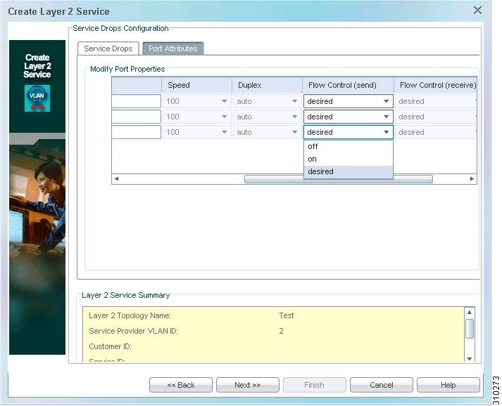
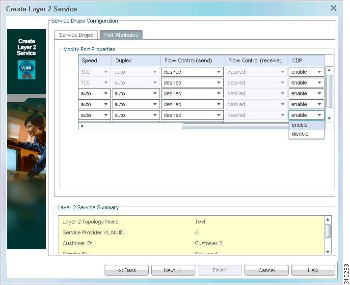
Ethernet port provisioning involves configuring the following parameters (see Figure H-3):
•
•
•
•
PoS port provisioning involves configuring the following parameters (see Figure H-3):
•
•
Figure H-3 Create Layer 2 Service—Modify Port Properties
Enable
Interface {FastEthernetN|GigabitEthernetM} [N = 0 to 11 and M = 0,1]No shutdownDisable
Interface {FastEthernetN|GigabitEthernetM} [N = 0 to 11 and M = 0,1]shutdownMTU Provisioning
Interface {FastEthernetN|GigabitEthernetM} [N = 0 to 11 and M = 0,1]mtu MTU [MTU = 64 to 9000]Speed Provisioning
Interface {FastEthernetN|GigabitEthernetM} [N = 0 to 11 and M = 0,1]speed Speed [Speed = 10/100/auto]Duplex Provisioning
Interface {FastEthernetN|GigabitEthernetM} [N = 0 to 11 and M = 0,1]duplex Duplex [Duplex = half/full/auto]Flow Control (Send) Provisioning
Interface {FastEthernetN|GigabitEthernetM} [N = 0 to 11 and M = 0,1]flowcontrol send Flow Control(send) [Flow Control = desired/off/on]Enable (No Shut)
Interface {POSN} [N = 0 or 1]No shutdownDisable (Shutdown)
Interface {POSN} [N = 0 or 1]shutdownMTU Provisioning
Interface {POSN} [N = 0 or 1]mtu MTU [MTU = 64 to 9000]Port Channel Provisioning
ML-series cards offer port channel (also known as link aggregation) for Gigabit Ethernet and Fast Ethernet ports.
Port channel is a trunking technology that groups together multiple, full-duplex, IEEE 802.3 Gigabit Ethernet/Fast Ethernet interfaces to provide fault-tolerant, high-speed links between switches, routers, and servers.
Creating or Modifying a Port Channel
interface port-channel channel-ID[no] shutdownmtu MTU-value [The range is from 64 to 9000]hold-queue HI-queue-value in [The range is from 0 to 4096]hold-queue HO-queue-value out [The range is from 0 to 4096]Deleting a Port Channel
no interface port-channel channel-IDCreating or Modifying a Port Channel Member
interface { FastEthernetN | GigabitEthernetM } [N=0 to 11, and M=0,1]no ip addressno mtuno shutdownchannel-group channel-ID { mode [active | passive] }lacp port-priority port-priority [The range is from 1 to 65535]Deleting a Port Channel Member
interface { FastEthernetN | GigabitEthernetM } [N=0 to 11, and M=0,1]no channel-group channel-IDno lacp port-priorityshutdownIEEE 802.17 RPR Base Card Configuration
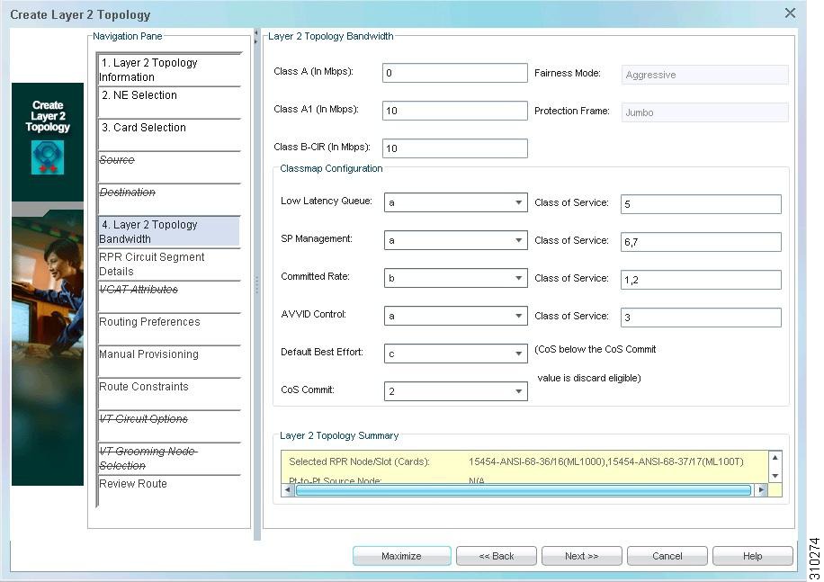
The base card configuration is a set of commands you enter when creating the Layer 2 topology. Use the Create Layer 2 Topology wizard > Layer 2 Topology Bandwidth pane (see Figure H-4) to define parameters for IEEE 802.17 RPR provisioning.
Figure H-4 Create Layer 2 Topology Wizard—IEEE 802.17 RPR Topology Creation
To create an RPR topology, apply the base card configuration to all ML-series cards in the RPR. The topology is reported as L2 Not Ready until the base card configuration is applied to all cards. Select an L2 Not Ready RPR in the L2 Topology table and choose Configuration > Enable L2 Service to enable the L2 service provisioning.
The IEEE 802.17 policy map configuration differs from the policy map configuration in the Cisco RPR. ML-series cards in 802.17 RPR mode support the following traffic classes:
•
–
–
–
•
–
–
•
You can modify the CoS value; the range is from 0 to 7.
Use the following commands to create the IEEE 802.17 RPR:
[Class map configuration]class-map match-any AVVID_VOICE_VIDEOmatch cos Low Latency Queue Class of Serviceclass-map match-any SP_MANAGEMENTmatch cos SP Management Class of Serviceclass-map match-any CIRmatch cos Committed Rate Class of Serviceclass-map match-any AVVID_CONTROLmatch cos AVVID Control Class of Serviceclass-map match-all BEST_EFFORTmatch any[Policy map configuration]policy-map POLICY_QOS_OUTclass AVVID_VOICE_VIDEOset rpr-ieee service-class Low Latency Queue [Possible values are a, b, c]class AVVID_CONTROLset rpr-ieee service-class AVVID Control [Possible values are a, b, c]class SP_MANAGEMENTset rpr-ieee service-class SP Management [Possible values are a, b, c]class CIRset rpr-ieee service-class Committed Rate [Possible values are a, b, c]class BEST_EFFORTset rpr-ieee service-class Default Best Effort [Possible values are a, b, c][Absolute bandwidth configuration]interface rpr-ieee 0rpr-ieee protection pref jumborpr-ieee tx-traffic rate-limit reserved Class A east [Class A range is from 0 to 48 Mb/s]rpr-ieee tx-traffic rate-limit reserved Class A west [Class A range is from 0 to 48 Mb/s]rpr-ieee tx-traffic rate-limit high Class A1 east [Class A1 range is from 1 to 48 Mb/s]rpr-ieee tx-traffic rate-limit high Class A1 west [Class A1 range is from 1 to 48 Mb/s]rpr-ieee tx-traffic rate-limit medium Class B-CIR east [Class B-CIR range is from 1 to 48 Mb/s]rpr-ieee tx-traffic rate-limit medium Class B-CIR west [Class B-CIR range is from 1 to 48 Mb/s]service-policy output POLICY_QOS_OUT
Note
In the commands listed above, the upper limit of the range value depends on the circuit size. For example, if x is the maximum range value in megabits per second (Mb/s):
•
•
•
•
•
•
•
•
•
Protection Support on ML-Series Cards
You can select IEEE 802.17 RPR ML1000 cards for protection in the Create Layer 2 Topology wizard > Card Selection pane (see Figure H-5).
To choose a working card, select any card in the Available Cards list and click Add Working.
To choose a protection card for a working card:
1.
2.
3.
Note
Figure H-5 Card Selection—Create Layer 2 Topology Wizard (IEEE 802.17 RPR)
After you select the protection, commands are issued on the active and protection ML1000 cards, as follows:
•
–
interface RPR-IEEE0mac-address MAC address of the interface [MAC address range is from 0000.1111.1111 to 0000.9999.9999]–
interface RPR-IEEE0mac-address MAC address of the interface [MAC address range is from 0000.1111.1111 to 0000.9999.9999]•
–
interface RPR-IEEE0rpr-ieee ri mode primary peer MAC address of the active card [MAC address range is from 0000.1111.1111 to 0000.9999.9999]–
interface RPR-IEEE0rpr-ieee ri mode secondary peer MAC address of the protection card [MAC address range is from 0000.1111.1111 to 0000.9999.9999]
Note
When changing ML1000 GE port states in a scenario with 802.17 RPR redundant interconnect protection configured, the primary ML card remains active if at least one GE port is up.
Conversely, if all GE ports are down, the redundant interconnect protection is triggered and the IEEE 0 interface shuts down on the primary card. When the IEEE 0 interface shuts down, the L2 topology state changes to Steering.
Wrap Status
When a PoS port in a Cisco RPR L2 topology shuts down, Prime Optical raises an alarm to indicate that the L2 topology has entered the corresponding protection state, which is referred to as the wrap state. The status of the Layer 2 topology changes from the original state (Complete or Incomplete) to Complete-Wrapped or Incomplete-Wrapped (see Figure H-6).
Figure H-6 Layer 2 Topology Table—Complete-Wrapped State
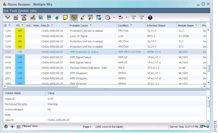
The Alarm Browser (see Figure H-7) displays a wrapped-state alarm.
Figure H-7 Alarm Browser—Complete-Wrapped State
Note
Steering Status
When an RPR-EAST or RPR-WEST port in a standard 802.17 RPR shuts down, Prime Optical raises an alarm to indicate that the L2 topology has entered the corresponding protection state, which is referred to as the Steering state. The status of the Layer 2 topology changes from the original state (Complete or Incomplete) to Complete-Steering or Incomplete-Steering (see Figure H-8).
Figure H-8 Layer 2 Topology Table—Complete-Steering State
The Alarm Browser (see Figure H-9) displays an RPR Protection Is Active alarm.
Figure H-9 Alarm Browser—Complete-Steering State
Note
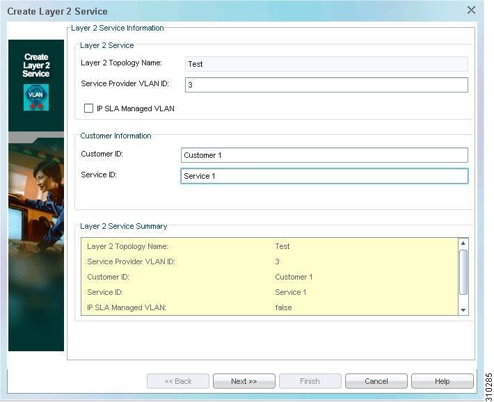
Creating Service Connections
Prime Optical contains an L2 service provisioning wizard to facilitate provisioning of VLANs over a defined L2 topology. You can define each Ethernet port as User-Network Interface (UNI) or Network-Network Interface (NNI). VLANs on an Ethernet port are referred to as port VLANs. VLANs on PoS and SPR ports (and their connected circuits) are referred to as service provider VLANs (or circuit VLANs).
You cannot mix NNI and UNI connections on the same port. Prime Optical supports the following types of service configurations:
•
•
•
•
The circuit VLAN range is from 1 to 4095. On an RPR, all valid circuit VLANs can be used; however, due to limited bridge group resources, each ML-series card can access only 255 circuit VLANs. Due to limited card-level bridge group resources, only 255 circuit VLANs can be used on a point-to-point circuit.
Note
For VLAN configurations, the port channel interface is treated as a new, single logical interface, even though it consists of multiple interfaces. The following Cisco IOS commands are sent to the ML card to configure the IEEE 802.1Q encapsulation on the port channel interface. (IEEE 802.1Q encapsulation is the only supported encapsulation type in link aggregation.)
interface port-channel port-channel-ID.VLAN-numberencapsulation dot1Q VLAN-numberbridge-group bridge-group-numberPort channel drops are of NNI type; therefore, no QoS policies are associated to port channel drops, as is true for any other NNI Ethernet drops.
Using the Quality of Service Policy Template
You must configure the following information in the L2 service provisioning and quality of service (QoS) profile wizards:
•
•
•
Prime Optical assigns an unused bridge group (BG) to the card. The range is from 1 to 255.
The following table lists the configuration information for a best-effort QoS profile. You can select the predefined profile and customize it, or create a new customized profile by using the Advanced option.
The following table lists the configuration information for the committed information rate/peak information rate (CIR/PIR) QoS profile. You can select the predefined profile and customize it, or create a new customized profile by using the Advanced option.
Note
Prime Optical allows you to define a QoS policy template, starting with the preceding predefined policies and customizing them within the following predefined ranges:
•
–
–
–
–
–
–
•
–
–
–
–
You can create your own advanced QoS policy by entering the customized QoS configuration based on the following parameters:
•
•
•
•
•
•
•
You must configure the following information in the L2 service provisioning and QoS profile wizards:
•
•
•
Prime Optical assigns an unused bridge group to the card. The range is from 1 to 255.
Note
For any drop-applied QoS profile, Prime Optical checks the available bandwidth and generates an error message if:
•
•
where the parameter totalBW is calculated as the sum of:
–
–
–
For each selected service drop, the configuration is done in three steps:
1.
2.
3.
The following sections describe the commands for each step.
Class Map Configuration
Configuring CIR/PIR Class Map
[Class map configuration for CIRPIR]Class-map match-all CLASS_BG BG_CIRPIRmatch bridge-group BGConfiguring Best-Effort Class Map
[Class map configuration for BESTEFFORT]Class-map match-all CLASS_BG BG_BESTEFFORTmatch bridge-group BGConfiguring Advanced Class Map
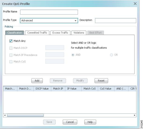
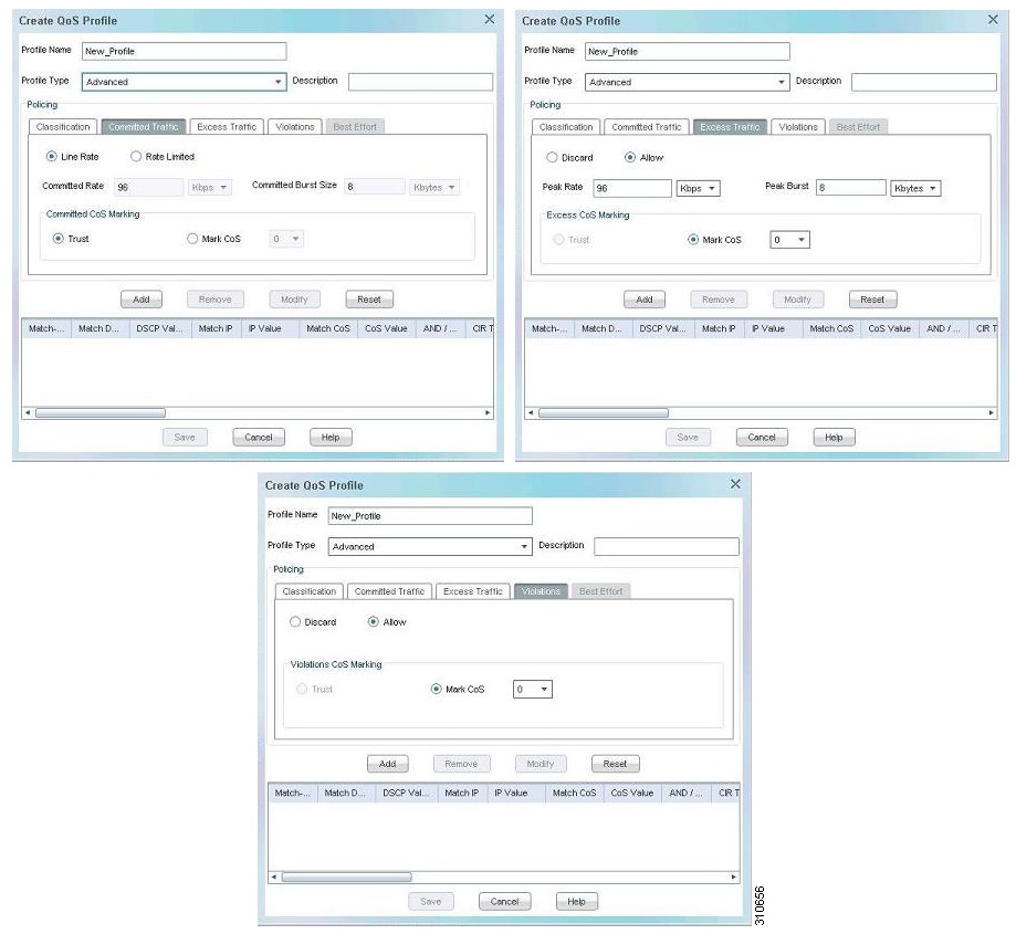
Figure H-10 and Figure H-11 show how to use the Create QoS Profile wizard to configure an advanced QoS profile.
Figure H-10 Create QoS Profile Wizard—Advanced Class Map Configuration (1 of 2)
Figure H-11 Create QoS Profile Wizard—Advanced Class Map Configuration (2 of 2)
Enter the following commands to create a QoS profile with advanced OR selection:
[Class map configuration for ADVANCED OR selection]class-map match-any CLASS_BG BG_ADVANCED_Service Drop Port_N [N number of policies will be configured on the Service Drop Port=0,1 for GigaEthernet and Service Drop Port=0 to 11 for FastEthernet][match ip dscp Match DSCP][If Match DSCP has been selected, the valid range is from 0 to 63][match ip precedence Match IP Precedence][If Match IP Precedence has been selected, the valid range is from 0 to 7][match cos Match CoS][If Match CoS has been selected, the valid range is from 0 to 7]
Note
QoS Profile Configuration
CIR/PIR QoS Profile
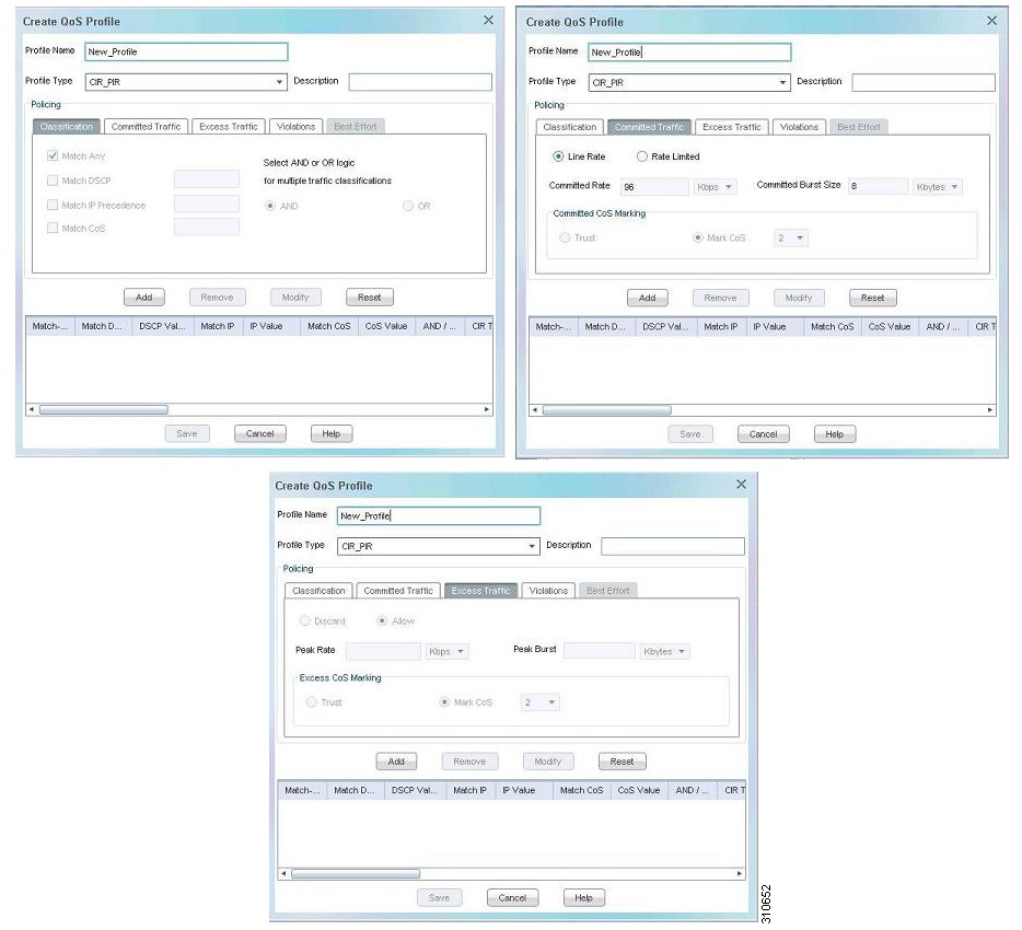
Figure H-12 is an example of how to create a CIR/PIR QoS profile.
Figure H-12 Create QoS Profile Wizard—CIR/PIR
Enter the following commands for policy map configuration of a CIR/PIR QoS profile:
[Policy map configuration command for the CIR/PIR QoS profile]Policy-map POLICY_{GIGE|FE}port_INClass CLASS_BG BG_CIRPIR[1. Case Line Rate selection]Police 96000 8000 conform-action set-cos-transmit 2 exceed-action set-cos-transmit 2[2. Case Rate Limited selection Excess Traffic Discarded]Police Committed Rate Committed Burst Size conform-action set-cos-transmit 1 exceed-action drop[3. Case Rate Limited selection Excess Traffic Allowed]Police Committed Rate Committed Burst Size Peak Burst pir Peak Rate conform-action set-cos-transmit 2 exceed-action set-cos-transmit 1 violate-action dropBest-Effort QoS Profile
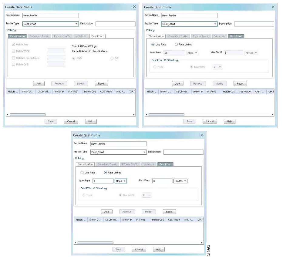
Figure H-13 is an example of how to create a best-effort QoS profile.
Figure H-13 Create QoS Profile Wizard—Best Effort
Enter the following commands to create a best-effort QoS profile:
[Policy map configuration for the BESTEFFORT QoS profile]Policy-map POLICY_{GIGE|FE}port_INClass CLASS_BG BG_BESTEFFORT[1. Case Line Rate selection]Police 96000 8000 conform-action set-cos-transmit 0 exceed-action set-cos-transmit 0[2. Case Rate Limited selection]Police Max Rate Max Burst conform-action set-cos-transmit 0 exceed-action dropAdvanced QoS Profile
Figure H-14 is an example of how to create an advanced QoS profile.
Figure H-14 Create QoS Profile Wizard—Advanced
[Policy map configuration for the ADVANCED QoS profile]Policy-map POLICY_{GIGE|FE}port_INClass CLASS_BG BG_ADVANCED_Service Drop Port_N[N number of policies will be configured on the Service Drop Port = 0,1 for Gigabit Ethernet and Service Drop Port = 0 to 11 for Fast Ethernet.]police Committed Rate Committed Burst Size [Peak Rate pir Peak Burst] conform-action {transmit|set-cos-transmit Committed CoS Marking Value} [exceed-action {drop|set-cos-transmit Excess CoS Marking Value}][violate-action {drop|set-cos-transmit Violation CoS Marking Value}][[Peak Rate pir Peak Burst] is applied only if Excess Traffic is Allowed.] [exceed-action drop is applied only if Excess Traffic is Discarded.][Trust option is never selectable for Excess Traffic or Violation tab. Mark CoS option is always used when the Excess or Violations is Allowed.][violation-action drop is applied only if Excess Traffic is Allowed and Violate Traffic is Discarded.]Bandwidth Data Service Provisioning
In the Control Panel > NE Service > CTC-Based SONET NEs or CTC-Based SDH NEs, select the Enable Bandwidth DSP check box to enable the bandwidth data service provisioning check during L2 service provisioning. The bandwidth utilization report shows available and used bandwidth for each L2 topology. Use this report during L2 service provisioning to verify whether the requested CIR is available on the topology. An error is returned if there is not enough bandwidth available for a drop port.
Interface Configuration
Adding UNI QinQ Access
Any port with mode dot1q-tunnel is a UNI QinQ access connection. Figure H-15 and Figure H-16 show how to add UNI QinQ access using the Create Layer 2 Service wizard.
Figure H-15 Create Layer 2 Service Wizard—Adding UNI QinQ Access
Figure H-16 Create Layer 2 Service Wizard—Configuring Service Drops
Enter the following commands to configure an interface:
[Interface configuration]Interface {GigabitEthernetport|FastEthernetport}Description QoS profile name[Prime Optical issues the L2protocol-tunnel all command and the result is the following set of commands]l2protocol-tunnel cdpl2protocol-tunnel stpl2protocol-tunnel vtpno cdp enableMode dot1q-tunnelBridge-group BGService-policy input POLICY_{GIGE|FE}port_INService-policy output POLICY_QOS_OUT[The following commands are not issued by Prime Optical; rather, these are default MLsettings]Bridge-group BG spanning-disableInterface SPR1.Service Provider VLANEncapsulation dot1q Service Provider VLANBridge-group BG[The following commands are not issued by Prime Optical; rather, these are default MLsettings]Bridge-group BG spanning-disableRemoving UNI QinQ Access
Enter the following commands to delete a UNI QinQ drop:
[Note the reverse order of commands]Interface SPR1.Service Provider VLANNo Bridge-group BGNo Encap dot1q Service Provider VLANNo Interface SPR1.Service Provider VLAN [Ignore the warning message]Interface {GigabitEthernetport|FastEthernetport}No Bridge-group BGNo Mode dot1q-tunnelNo L2protocol-tunnel allNo descriptionNo class-map CLASS_BG BG_{CIRPIR|BESTEFFORT|ADVANCED_Service Drop Port_N}[For Advanced QoS, remove all of the N number of class maps][When removing the last connection from a port]No Policy-map POLICY_{GIGE|FE}port_INNo Service-policy output POLICY_QOS_OUTAdding UNI dot1Q Access
Figure H-17 is an example of the Create Layer 2 Service wizard for adding UNI dot1Q access.
Figure H-17 Create Layer 2 Service Wizard—Adding UNI dot1Q Access
The port is recognized as UNI if you enter the service-policy input command on the port interface; otherwise, the port is recognized as NNI. Every subinterface is a dot1q connection. The classification of UNI versus NNI is based on the port-level parsing. A connection is untagged if you enter the encap dot1q 1 command. The multiple class map and QoS policy configurations for advanced QoS are similar to the QinQ Access example shown in Figure H-17.
Enter the following commands to create a UNI Dot1q:
[Interface configuration][First time only; first dot1q on this UNI port]Interface {GigabitEthernetport|FastEthernetport}Service-policy input POLICY_{GIGE|FE}port_INService-policy output POLICY_QOS_OUTInterface {FastEthernetport|GigabitEthernetport}.Port VLANDescription QoS profile nameEncapsulation dot1q Port VLANBridge-group BG[In the following command executed by Prime Optical, RSTP is not enabled]Bridge-group BG spanning-disableInterface SPR1.Service Provider VLANEncapsulation dot1q Service Provider VLANBridge-group BG[In the following command executed by Prime Optical, RSTP is not enabled]Bridge-group BG spanning-disableRemoving UNI dot1Q Access
Enter the following commands to delete a UNI Dot1q:
[Note the reverse order of commands]Interface SPR1.Service Provider VLANNo Bridge-group BGNo Encap dot1q Service Provider VLANNo Interface SPR1.Service Provider VLAN [Ignore the warning message]Interface port.Port VLANNo Bridge-group BGNo Encap dot1q Port VLANNo descriptionNo Interface port.Port VLAN [Ignore the warning message]Policy-map POLICY_{GIGE|FE}port_INNo Class BG BG_{CIRPIR|BESTEFFORT|ADVANCED_Service Drop Port_N}[For Advanced QoS, remove all of the N number of class maps]No class-map CLASS_BG BG_{CIRPIR|BESTEFFORT|ADVANCED_Service Drop Port_N}[For Advanced QoS, remove all of the N number of class maps][When removing the last connection from a port]No Policy-map POLICY_{GIGE|FE}port_INNo Service-policy output POLICY_QOS_OUTAdding UNI Untagged Access
UNI untagged access is similar to UNI dot1Q access with port VLAN ID = 1.
Adding NNI dot1Q Access
Enter the following commands to create an NNI Dot1Q:
[Interface configuration][First time only; first connection on this port]Interface {FastEthernetport|GigabitEthernetport}Service-policy output POLICY_QOS_OUTInterface {FastEthernetport|GigabitEthernetport}.Port VLANEncap dot1q Port VLANBridge-group BGInterface spr 1.Server Provider VLANEncap dot1q Server Provider VLANBridge-group BGRemoving NNI dot1Q Access
Enter the following commands to delete an NNI Dot1Q:
[Note the reverse order of commands]Interface spr 1.Server Provider VLANNo Bridge-group BGNo Encap dot1q Server Provider VLANNo Interface spr 1.Circuit VLAN [Ignore the warning message]Interface port.Port VLANNo Bridge-group BGNo Encap dot1q Port VLANNo Interface {FastEthernetport|GigabitEthernetport}.Port VLAN [Ignore the warning message][When removing the last connection from a port]No Service-policy output POLICY_QOS_OUTIP Service-Level Agreement on ML-Series Cards
IP SLA is an application embedded in Cisco IOS, which enables you to monitor service-level agreements (SLAs) on IP networks. Service levels are measured by downtime, bandwidth, latency, jitter, packet loss, and so on. Using the IP SLA application, you can verify service guarantees, increase network reliability by validating network performance, proactively identify network issues, and increase return on investment (ROI) by easing the deployment of new IP services.
IP SLA can be configured only on ML-series cards participating in point-to-point and RPR L2 topologies.
Note
Three steps are required to enable IP SLA features:
Create a Managed VLAN
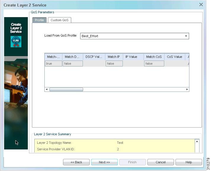
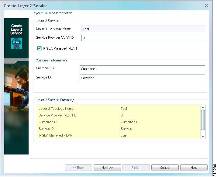
Create a managed VLAN by selecting IP SLA Managed VLAN in the Layer 2 Service wizard (see Figure H-18) to create a managed VLAN. You can create managed VLANs only on already existing point-to-point and RPR L2 topologies.
Figure H-18 Layer 2 Service Wizard—Managed VLAN-Enable
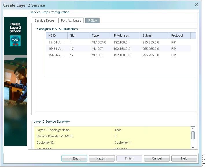
In the Service Drops Configuration pane > IP SLA tab (see Figure H-19), IP addresses are automatically generated and assigned to all of the service drop points that Prime Optical manages.
Figure H-19 Create Layer 2 Service Wizard—IP SLA
For information about commands that are issued based on the provisioning in the Service Drops and Port Attributes tabs, see Creating Service Connections.
The following commands are issued when you assign an IP address to the service drop and specify the routing protocol.
IP Address Assignment
ip address IP Address Subnet [IP Address range is from 192.168.0.1 to 192.168.255.255.
Subnet value is 255.255.0.0.]
Routing Protocol Assignment
bridge bridgegroupno route ip [Unique bridgegroupno is created by Prime Optical. The range
is from 1 to 255.]
Create an IP SLA Session
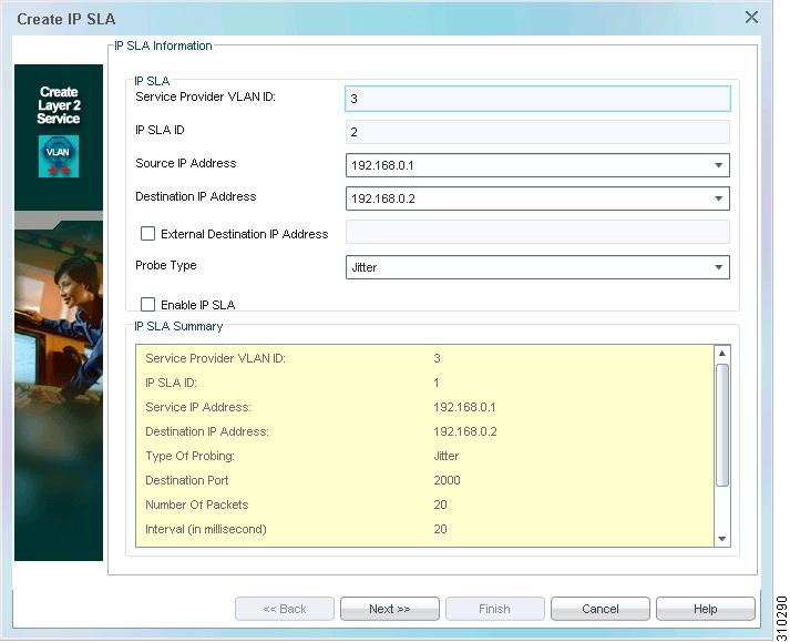
Create an IP SLA session between a pair of ML-series cards, or between an ML-series card and non-ML IP addresses. Select either Cisco-supported service points or external-destination IP addresses.
You can use the VLAN table (when a managed VLAN is selected) with the Create IP SLA wizard (see Figure H-20) to provision the IP SLA session.
Figure H-20 Create IP SLA Wizard
Note
Prime Optical automatically generates the IP SLA ID. The service drop points are displayed in the source and destination points, and you can pick up any drop point. You can specify a non-Prime Optical supported destination. IP SLA can be enabled during or after creation of the IP SLA session.
Note
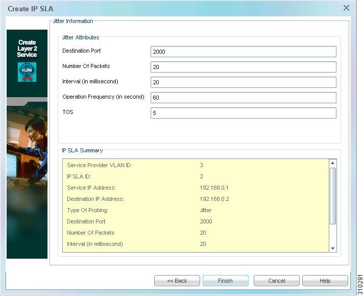
Two types of probes are supported: jitter and echo. Based on the probe type you select in the Create IP SLA wizard, you must enter additional information.
•
–
–
–
–
–
Figure H-21 Create IP SLA Wizard—Jitter Probe
Prime Optical issues the following commands on the source:
rtr IPSLA ID [IPSLA ID number range is from 1 to 2147483647]type jitter dest-ipaddr Destination IP Address dest-port Destination Port num-packets Number of Packets interval Intervaltos TOS frequency Operation FrequencyThe RTR responder is then configured on the destination for jitter operation. For a Prime Optical-supported destination (any ML-series cards), Prime Optical issues the following command on the destination:
rtr (responder)
Note
•
rtr IPSLA ID [IP SLA number range is from 1 to 2147483647]type echo protocol ipIcmpEcho Destination IP Address source-ipaddr Source IP Address[Destination IP Address could be a Prime Optical-managed ML card or an external device. Source IP Address is always a Prime Optical-managed ML card.]
Note
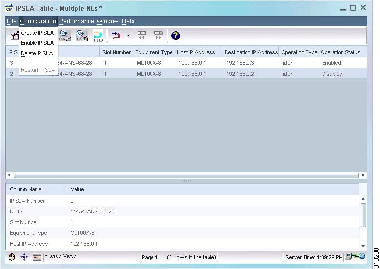
Manage the IP SLA Session
To begin collecting, enable the IP SLA session. The operation ends after 3600 seconds, but you can restart it from the Restart IP SLA menu.
Use the IP SLA table (see Figure H-22) to enable, restart, and delete IP SLA.
Figure H-22 IP SLA Table
Use the following commands to enable, restart, and delete IP SLA:
Enable IP SLA
rtr schedule IPSLA ID start-time now [IP SLA Number range is from 1 to 2147483647]Restart IP SLA
rtr restart IPSLA ID [IP SLA Number range is from 1 to 2147483647]Delete IP SLA
No rtr IPSLA ID [IP SLA Number range is from 1 to 2147483647]
Note
The following table lists the PM data retrieved on IP SLA for jitter. To view the statistics, choose IP SLA Table > Performance (see Figure H-22).
Enabling or Disabling Rapid Spanning Tree Protocol
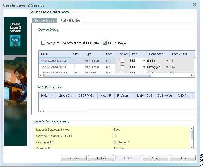
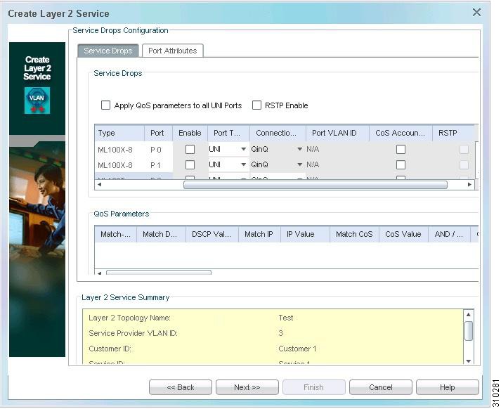
You can enable Rapid Spanning Tree Protocol (RSTP) on UNI dot1Q, UNI Untagged, and NNI dot1Q ports by selecting the RSTP for the selected drop port and then checking the RSTP Enable check box (see Figure H-23). To disable RSTP, select the RSTP for the selected drop port and uncheck the RSTP Enable check box.
Note
Figure H-23 Create Layer 2 Service Wizard—RSTP Enable
Click Next to configure QoS parameters as required (see Figure H-24).
Figure H-24 Create Layer 2 Service Wizard—QoS Parameters
If the RSTP Enable check box is checked, Prime Optical issues the following command specified for adding a drop:
[Configure RSTP; this command is issued once for VLANs]bridge BG protocol rstp[Enable RSTP on the selected drop]Interface {FastEthernetport|GigabitEthernetport}.Port VLANBridge-group BGThe following command is issued when you disable RSTP from a drop:
[Disable RSTP on the selected drop]Interface {FastEthernetport|GigabitEthernetport}.Port VLANBridge-group BGBridge-group BG spanning-disabled [Disable RSTP on the selected drop]
Note
•
Enabling or Disabling Cisco Discovery Protocol
You can enable or disable Cisco Discovery Protocol (CDP) when:
•
Creating a Layer 2 Service
In the Create Layer 2 Service wizard > Port Attributes tab > CDP drop-down list (see Figure H-25), choose enable or disable to enable or disable CDP.
Figure H-25 Create Layer 2 Service Wizard—Enable or Disable CDP
Modifying Layer 2 Service Drops
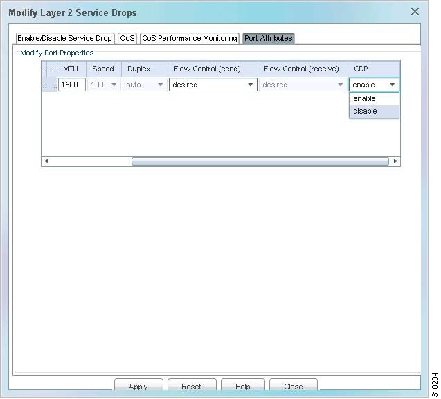
In the Modify Layer 2 Service Drops wizard > Port Attributes tab > CDP drop-down list (see Figure H-26), choose enable or disable to enable or disable CDP. Click Apply.
Figure H-26 Modify Layer 2 Service Drops Wizard—Enable or Disable CDP
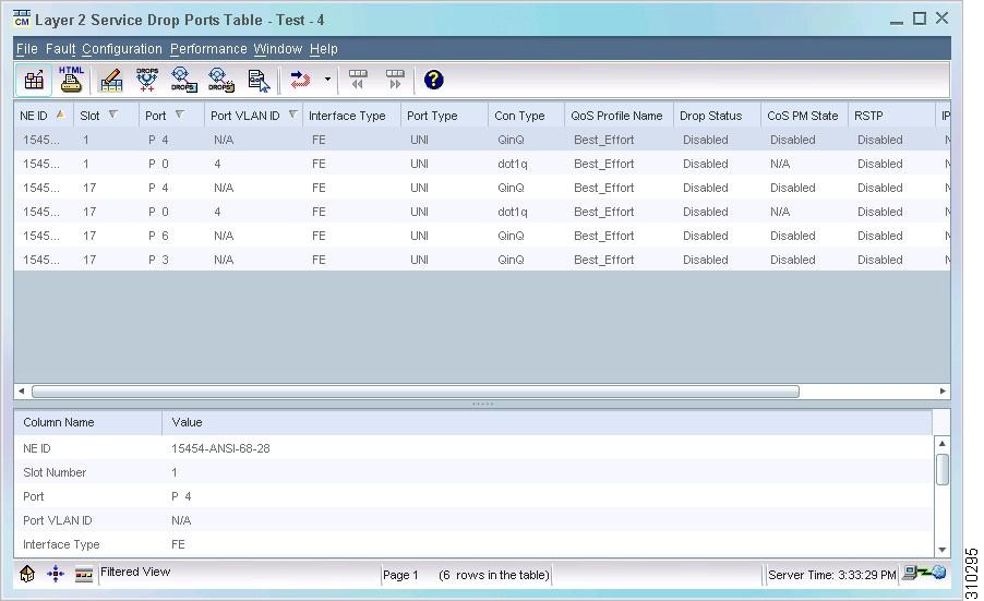
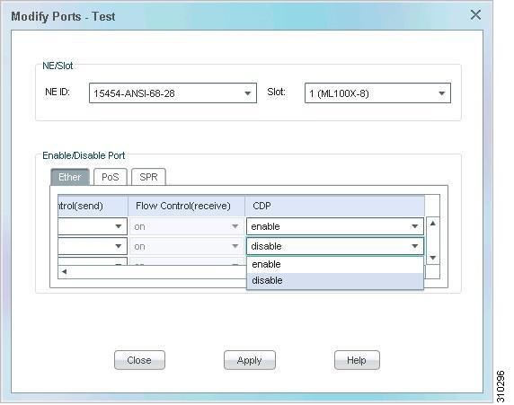
Modifying Drops
Step 1
Step 2
Step 3
Figure H-27 Layer 2 Service Drop Ports Table
Step 4
Figure H-28 Modify Ports
Step 5
Prime Optical issues the following command when you enable CDP on a selected drop:
Interface {FastEthernetport|GigabitEthernetport}.Port-VLANcdp enablePrime Optical issues the following command when you disable CDP on a selected drop:
Interface {FastEthernetport|GigabitEthernetport}.Port-VLANno cdp enableML Management Troubleshooting
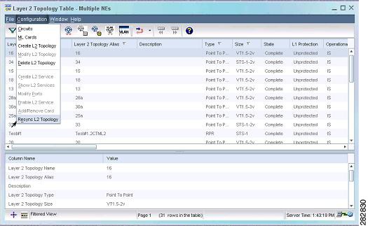
If a problem arises during the initial synchronization, you can resynchronize the Layer 2 topology by choosing Configuration > Resync L2 Topology in the Layer 2 Topology table (see Figure H-29).
Note
Alternative methods of resynchronization are:
•
•
Although effective, these methods cause a time lag that affects other functions, such as inventory collection and circuit discovery.
Figure H-29 Layer 2 Topology Table—Resynchronize L2 Topology
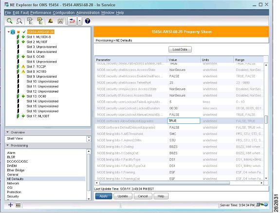
ML Version Up
When you upgrade a node, you can choose to upgrade the software running on the ML-series cards at a later time. The Version Up feature allows you to delay upgrading the ML-series card, and to choose which ML-series card to upgrade to the new version. By using this feature, you can also view the state of the node with respect to the upgrade, which can be:
•
•
To enable the Version Up feature, complete the following steps:
1.
Figure H-30 NE Explorer—NE Defaults Tab
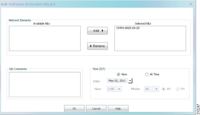
2.
Figure H-31 Bulk Software Activation Wizard
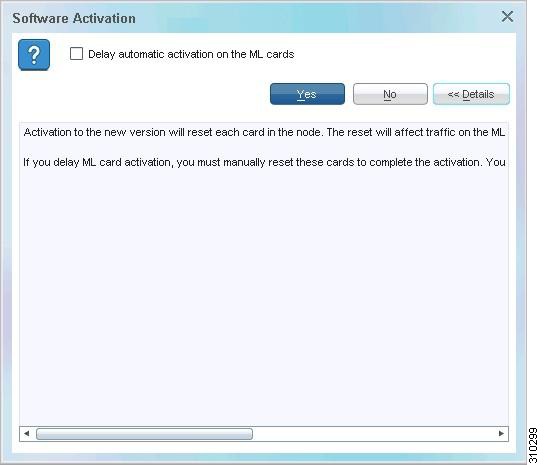
During NE software activation, you are asked if you want to delay the software upgrade on the ML-series cards (see Figure H-32). For specific instructions, see Delaying Software Activation on the ML-Series Cards.
Figure H-32 Software Activation
Note
•
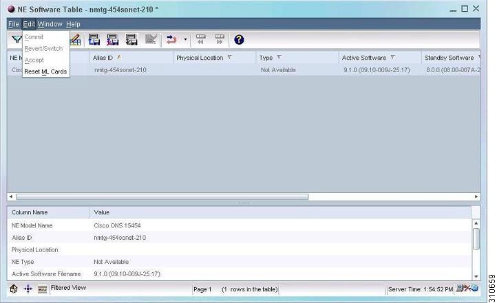
After a successful partial software activation on the NE, the NE Software table (see Figure H-33) displays True in the Partial Upgrade column, which indicates that the activation is pending for ML-series cards.
3.
–
–
The Partial Upgrade column in the NE Software table displays FALSE when all ML-series cards are upgraded to the current version.
Figure H-33 NE Software Table—Reset ML Cards
Enable L2 Service Command Enhancement
The enable L2 service command has been enhanced. (For details, see Enabling Layer 2 Services.)
The enable L2 service command is used only when the resynchronization status of the topology is L2 Service Not Ready, and its main purpose is to change the Layer 2 topology into a resynchronization status of Complete so that a VLAN can be created.
Instead of commanding the default base card configuration on all ML-series cards in the topology to be downloaded, this command downloads a customized base card configuration on only the selected Layer 2 topology ML-series cards that do not have the customized configuration and are in a synchronized configuration state (barebone file downloaded).
This command applies to point-to-point, Cisco RPR, and 802.17 RPR Layer 2 topologies.