-
Cisco Prime Optical User Guide, 9.6
-
Preface
-
Chapter 1: Introduction
-
Chapter 2: Basic Concepts
-
Chapter 3: Building the Network
-
Chapter 4: Maintaining an Efficient Network
-
Chapter 5: Configuring Hardware
-
Chapter 6: Provisioning Cards
-
Chapter 7: Provisioning Services and Connections
-
Chapter 8: Managing Security
-
Chapter 9: Managing Faults
-
Chapter 10: Managing Performance
-
Chapter 11: Managing Inventory
-
Chapter 12: Managing Southbound and Northbound Interfaces
-
Chapter 13: Configuring MPLS-TP Using the CPT System
-
Appendix A: Icons and Menus Displayed in Prime Optical
-
Appendix B: NE Explorer Information
-
Appendix C: Slot Property Information--Common, DWDM, Electrical, and Ethernet Cards
-
Appendix D: Slot Property Information—FC_MR-4, FMEC, Multirate, and Optical Cards
-
Appendix E: Performance Data
-
Appendix F: Error Messages
-
Appendix G: Troubleshooting
-
Glossary
-
 Feedback
Table Of Contents
1.1 Overview of Cisco Prime Optical
1.2 Prime Optical Integration with Prime Central
1.3 What's New in Prime Optical 9.6
1.6 General Features of Prime Optical
1.6.4 Launching Context-Sensitive Information
1.6.8 Exporting Alarms and Events
1.6.16 Viewing Licensing (NE Audit) Information
1.7.1 Prime Optical Documentation Set
1.7.2 Related Cisco NE Documentation
Introduction
Cisco Prime Optical (formerly Cisco Transport Manager) is a carrier-class, multitechnology management system that integrates the end-to-end management of traditional transport networks and new carrier packet transport networks. It can help maintain the integrity of existing services, plus deliver interactive, content-based services and high-bandwidth applications.
Cisco Prime Optical manages the entire Cisco optical portfolio, including:
•
Metro core
•
•
•
Prime Optical also serves as a foundation for integration into a larger overall Operations Support System (OSS) environment by providing northbound gateway interfaces to higher-layer management systems.
For Cisco network element (NE) documentation, see Related Cisco NE Documentation.
This chapter contains the following sections:
•
•
•
•
1.1 Overview of Cisco Prime Optical
This section provides a high-level overview of how Prime Optical fits into the network.
Prime Optical provides advanced capabilities in fault, configuration, performance, and security management across the element and network management layers of the Telecommunication Management Network (TMN) reference architecture.
Prime Optical manages the following optical NEs:
•
–
–
–
–
–
–
–
–
–
–
–
•
•
•
•
•
•
•
•
•
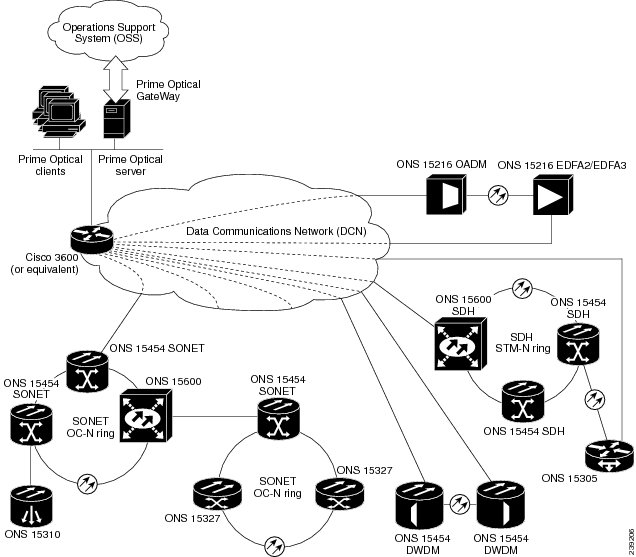
Prime Optical GateWay is an architectural component that provides northbound element management system-to-network management system (EMS-to-NMS) interface mediation. Prime Optical GateWay enables service providers to integrate Prime Optical with their OSSs by using open, standard interfaces. Prime Optical offers Simple Network Management Protocol (SNMP) and Common Object Request Broker Architecture (CORBA) interface options.
Note
Prime Optical provides a comprehensive management solution as illustrated in the following figure.
Figure 1-1 Prime Optical Comprehensive Management Solution
1.2 Prime Optical Integration with Prime Central
Prime Optical can be used as a standalone product or as part of the Cisco Prime Central. When it is installed as part of the suite, you can launch Prime Optical from the Prime Central portal. For more information about Prime Central, see the documentation for Cisco Prime Central.
When Prime Optical and Cisco Prime Network is installed as part of the suite, you can view additional device details from Prime Network for Carrier Packet Transport (CPT) and Cisco Aggregation Services Router 9000 (ASR 9K) NEs. To launch Prime Network from these NEs:
Step 1
Step 2
1.3 What's New in Prime Optical 9.6
The following table describes changes and enhancements in Prime Optical 9.6.
Table 1-1 New Features in Prime Optical 9.6
Compatibility with the Prime for IP NGN 1.1 suite
Prime Optical 9.6 is compatible with the Prime for IP NGN 1.1 suite, where you can use the Prime Central portal to launch Prime Optical.
Dual-server setup
The dual-server installation process includes the following updates:
•
•
•
Ability to select user other than root
You can select optusr user, instead of root user, to operate Prime Optical.When the optusr user is selected, the following applies:
•
•
•
Availability of local redundancy and automatic failover for high availability (HA) installations on Linux
The HA configuration on Linux now supports local redundancy and automatic failover.
To obtain the Cisco Prime Optical 9.6 High Availability Installation Guide, contact your Cisco account representative.
Central Authentication Service (CAS)
With a single sign-on (SSO) CAS solution, different applications can authenticate to one authoritative source of trust.
New Prime Optical Home page
After logging into Prime Optical, a new Prime Optical Home page appears. The Home page provides the following:
•
•
•
•
Cisco Prime Optical 9.6 Installation Guide
Ability to launch NE Explorer from the Alarm Browser table
You can launch NE Explorer by double-clicking a row in the Alarm Browser.
Ability to launch the circuit table from the Alarm Browser
You can launch the circuit table from the Alarm Browser window and view the circuits affected by an alarm.
Ability to enable or disable TCA Management from the Control Panel
You can enable or disable TCA Management by selecting the check box in the Control Panel.
Multishelf NEs support up to 50 shelves and racks
In Prime Optical 9.6, a multishelf NE supports up to 50 shelves and racks.
Network Maps
Network Maps in Prime Optical 9.6 support the following:
•
•
•
•
•
Photonic Path Trace
Prime Optical 9.6 displays Photonic Path Trace (PPT) details for Layer 1 services of OCHNC and OCHTrail circuits.
L1 Circuit Reports
The new Circuit Report feature applies to all Layer 1 circuits that can be shown in the Circuit Table of previous Prime Optical releases.
Support for CTC-Based NE Release 9.6
Expands Prime Optical scope to include operations, administration, management, and provisioning (OAM&P) for the following CTC-based NE releases:
•
•
•
•
Support for 10x10G_LC, 100G_LC_C, and CFP_LC
10x10G_LC, 100G_LC_C, and CFP_LC cards are supported on ONS 15454 M2 and ONS 15454 M6 platforms.
Support for 15216-MD-48-ODD and 15216-MD-48-EVEN, 48-channel mux/demux unit
The Cisco ONS 15216 48-channel mux/demux unit is a new ONS 15216 FlexLayer unit that allows 48 channels of ITU wavelengths to be placed onto a single fiber, and removes 48 channels of ITU wavelengths from a single fiber. Release 9.6 supports the 15216 48-channel mux/demux odd/even unit:
•
•
Support for 10 new passive DCU modules
The ONS 15216 FBGDCU has 10 modules. The slot can accommodate any one of the following modules:
•
•
•
•
•
•
•
•
•
•
Support for OTU Mapping
You can create an OCHCC circuit with OTU Mapping. The following new values are added to OTU Mapping:
•
•
Note
•
Circuit Name can now support 80 characters
The maximum length for a Prime Optical circuit name is now 80 characters. In earlier Prime Optical releases, the maximum circuit name length was 48 characters.
Customization of generic unmanaged NEs to support DWDM topology with IP address and optical configuration
Prime Optical R9.6 supports customization of unmanaged NEs to support the following:
•
•
•
•
•
Discovery of DWDM pluggable line insertion modules (PLIMs) on the Cisco Carrier Routing System 3 (CRS-3)
Prime Optical R9.6 supports the discovery of DWDM PLIMs on the CRS-3. Prime Optical discovers the CRS-3 DWDM PLIMs through ONS 15454 NEs.
Unmanaged NE CRS-3 supports the following:
·You can assign the type of the NE (CRS-1, CRS-3, ASR9K) and the IP address.
·You can create patchcords that connects any CRS port to the ROADM device.
·Create manual links between ONS and unmanaged NEs.
·Ability to cross-launch Prime Network from the unmanaged device.
·Ability to leverage the existing parameter of the unmanaged NE to specify the port of the unmanaged NE is connected to the patch chord.
External Authentication
The external authentication feature has been removed from Prime Optical.
—
Login Preferences
Login Preferences in the Control Panel>Security Properties pane has been removed from Prime Optical.
—
Lockout
The ability to set account lockout settings has been removed from Prime Optical.
—
Session Recovery
The Session Recovery tab in the Control Panel>Recovery Properties pane has been removed from Prime Optical.
—
1.4 Key Functionality
Prime Optical provides the following key functionality:
•
•
•
•
•
•
•
•
•
•
•
•
•
•
•
•
•
•
1.5 Key GUI Components
This section describes the following key components in the Prime Optical GUI:
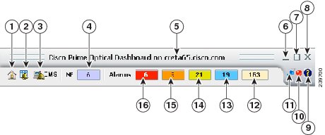
1.5.1 Dashboard
The Dashboard shows useful alarm and NE information in one easily accessible location.
Figure 1-2 Prime Optical Dashboard
Note
1.5.2 Domain Explorer
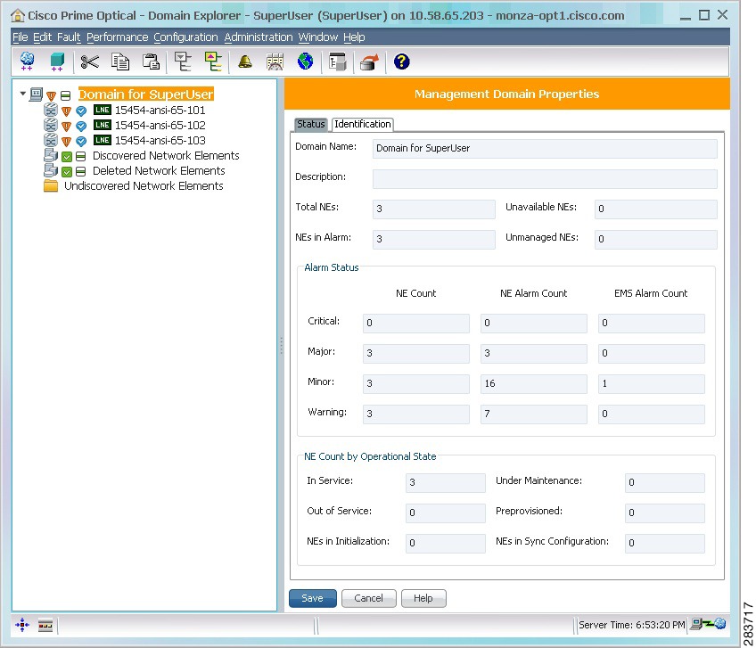
The Domain Explorer window opens when you log into Prime Optical. The Domain Explorer is the Prime Optical home window and provides a logical view of the network plus alarm, connectivity, and operational status. To log out of Prime Optical, choose File > Exit from the Domain Explorer window.
Figure 1-3 Domain Explorer
The Domain Explorer window is divided into two sections: the topology tree and the properties pane. The topology tree on the left side of the window consists of a management domain, groups, and NEs, which are displayed in a hierarchical format. You can drag and drop NEs to reposition them in the topology tree. The properties pane on the right side of the window shows detailed information about the object that is selected in the topology tree.
Tip
By default, the Domain Explorer contains the following groups that are visible to SuperUser and NetworkAdmin users only:
•
•
•
Note
•
For information about populating the Domain Explorer with new groups, gateway NEs (GNEs), or NEs, see Chapter 3 "Building the Network."
The Domain Explorer has three properties panes: Management Domain Properties, Group Properties, and Network Element Properties.
1.5.2.1 Management Domain Properties
The Management Domain Properties pane displays information about the management domain that is currently selected in the Domain Explorer or Subnetwork Explorer tree. The Prime Optical management domain consists of all the NEs managed by the Prime Optical server where the Prime Optical client connects.
The management domain can also contain groups or subnetworks that give you the flexibility to subdivide the domain you are monitoring. For example, a group or subnetwork can represent all NEs within a geographical location.
To display all first-level nodes under the management domain, click the expand icon next to the management domain name in the topology tree. If any of the groups, subnetworks, or NEs have an alarm condition, an icon representing that condition is displayed next to the management domain name.
The Management Domain Properties pane has two tabs: Status and Identification.
1.5.2.1.1 Status Tab
The following table describes the Status tab fields.
1.5.2.1.2 Identification Tab
The following table describes the Identification tab fields.
Note
1.5.2.2 Group Properties and Network Partition Properties
The Group Properties pane or Network Partition Properties pane displays information about the group or network partition that is currently selected in the topology tree. The Group Properties pane is part of the Domain Explorer; the Network Partition Properties pane is part of the Subnetwork Explorer.
A group consists of other groups or NEs. Groups give you the flexibility of subdividing the management domain you are monitoring. For example, a group can represent all NEs within a geographical location.
A network partition is a group of subnetworks or a group of NEs that is managed by the same NE service. Different network partitions mean different NE services. For information about NE services, see Viewing and Modifying NE Service Properties.
Click the expand icon next to a group or network partition in the topology tree to view the objects that are assigned to that group or network partition. The same group or network partition can have multiple instances in the topology tree. The contents of all instances of a group or network partition are always the same. Any changes to one instance of a group or network partition will be reflected in all instances of that group or network partition.
You can add and delete groups or network partitions; however, the option to delete a group or network partition is not available until all objects are removed from the group or network partition. If the group or network partition has multiple instances in the topology tree, you can delete all but the last instance of the group or network partition.
The Group Properties or Network Partition Properties pane has two tabs: Status and Identification.
1.5.2.2.1 Status Tab
The following table describes the Status tab fields.
1.5.2.2.2 Identification Tab
The following table describes the Identification tab fields. Only users with the appropriate user access profile can edit these fields.
Note
1.5.2.3 Network Element Properties
The Network Element Properties pane displays information about the NE that is currently selected in the tree. An NE represents a Cisco ONS 15216, ONS 15305, ONS 15310 CL, ONS 15310 MA SONET, ONS 15310 MA SDH, ONS 15327, ONS 15454 SONET, ONS 15454 SDH, ONS 15454-M2, ONS 15454-M6, ONS 15530, ONS 15540, ONS 15600 SONET, ONS 15600 SDH, or unmanaged/other vendor node.
The same NE can have multiple instances in the tree. The contents of all instances of the same NE are always the same. Any changes to one NE instance are reflected in all instances of that NE. Regardless of the number of instances an NE has in the tree, you can delete one or all instances of that NE. When the final instance of an NE is deleted, the deleted NE moves to the Deleted Network Elements group.
The Network Element Properties panes for most NEs have the following tabs: Status, Identification, Address, NE Authentication, and TL1 Tunnel. The NE Properties pane for passive NEs has only one tab: Identification.
1.5.2.3.1 Status Tab
The following table describes the fields in the Status tab. Display-only fields have a gray background.
Table 1-6 Field Descriptions for the Status Tab
NE ID
Name of the selected NE.
Description
Information that a user entered to describe the NE.
NE Model
Model of the selected NE.
Alarm Status
Total number of critical, major, minor, and warning alarms currently existing on the selected NE.
Communication State
Current communication state of the selected NE. Communication states can be one of the following:
•
•
•
•
Operational State
Current operational state of the selected NE. You can change the operational state.
PM Collection (not applicable to the ONS 15216)
15 Min/1 Day: Check the 15 Min check box to enable 15-minute PM data collection. Check the 1 Day check box to enable 1-day PM data collection. By default, PM data collection is disabled for both 15-minute and 1-day options.
15 Min Robust/1 Day Robust: If the 15 Min check box is checked and the NE supports robust PM collection, you can check the 15 Min Robust check box to enable robust PM collection. If the 1 Day check box is checked and the NE supports robust PM collection, you can check the 1 Day Robust check box to enable robust PM collection. Robust PM collection is performed according to the selected PM collection state when the NE or server is available.
Note
Robust PM data collection applies only to CTC-based NEs1 and to the ONS 15305, ONS 155302 , ONS 15540 ESP3 , and ONS 15540 ESPx2 NEs. Robust PM data collection is not supported for the ONS 15216.Audit Trail State (applicable to CTC-based NEs)
Whether the audit trail collection is enabled or disabled. You can change the setting. Audit trail collection is disabled by default.
Note
1 For CTC-based NEs, you can collect up to 8 hours of 15-minute robust PM data and up to the previous day's 1-day robust PM data.
2 For ONS 15530 and ONS 15540 ESPx NEs, you can collect up to 24 hours (96 previous missed intervals) of 15-minute robust PM data and up to the previous day's 1-day robust PM data.
3 For ONS 15540 ESP NEs, you can collect up to 24 hours (96 previous missed intervals) of 15-minute robust PM data.
1.5.2.3.2 Identification Tab
The following table describes the fields in the Identification tab. Display-only fields have a gray background. Fields displayed vary by NE type.
Table 1-7 Field Descriptions for the Identification Tab
NE ID
Name of the selected NE.
Alias
Alias name of the selected NE.
Description
Information that a user entered to describe the NE.
NE Model
Model of the selected NE.
NE Type
Type of NE.
Vendor Name
Vendor name.
Software Version
Software version that is running on the NE.
Version Name
String name tag that identifies the NE and the associated software version. The version name that is displayed is dependent on the software version. If the software version is:
•
•
–
–
Location Name
Geographic location of the selected NE.
1.5.2.3.3 Address Tab
The following table describes the fields in the Address tab.
1.5.2.3.4 NE Authentication Tab
The NE Authentication tab allows you to specify usernames and passwords for the Prime Optical server and command-line interface (CLI) connections to the selected NE. The following table describes the fields in the NE Authentication tab. Fields shown depend on the type of NE selected; the field is unavailable or not displayed if it does not apply to the selected NE.
Table 1-9 Field Descriptions for the NE Authentication Tab
SNMP Protocol
Specify the SNMP protocol from the drop-down list. Values are:
•
•
•
Username
Username of Prime Optical user enabled for SNMPv3 communication. When you add the NE, use the wizard to set parameters for the SNMPv3 user.
Authentication Protocol
Choose the authentication protocol to use for authenticating the user. Values are None, MD5 (the default), or SHA.
Authentication Password
Enter the password that the OSS client uses to log into the Prime Optical server. The password must contain:
•
•
•
•
Note
Confirm Authentication Password
Re-enter the password to confirm it.
Privacy Protocol
Specify the protocol to use for communicating the value of the SHA or DES fields. Select the privacy protocol for the NBI user. You can choose one of the following:
•
•
Privacy Password
Enter the password used to decrypt the message payload. Use this password if the Prime Optical user encryption mode for communication is NONE or DES.
Confirm Privacy Password
Re-enter the privacy password to confirm it.
Username
Username that the Prime Optical server uses to connect to NEs.
Password
Password to use for Prime Optical server-to-NE connections.
Confirm Password
Re-enter the password to confirm it.
Username
Username to use for CLI-to-NE connections.
Password
Password to use for CLI-to-NE connections.
Confirm Password
Re-enter the password to confirm it.
1 This field applies to NEs that have a TL1 interface and are provisioned through TL1 (for example, the ONS 15216 EDFA2, EDFA3, and OADM).
2 This field applies to NEs that have a CLI and are provisioned through CLI.
1.5.2.3.5 TL1 Tunnel Tab
The TL1 Tunnel tab is available only for TNEs (NEs reachable through a TL1 connection) and allows you to specify TNE settings. Prime Optical can connect to a TNE that belongs to an OSI network behind a non-Cisco GNE. The following NE models support TL1 tunnels: ONS 15310 CL, ONS 15310 MA SONET, ONS 15310 MA SDH, ONS 15327, ONS 15454 SONET, and ONS 15454 SDH.
The following table describes the fields in the TL1 Tunnel tab. All fields are dimmed (with a gray background) when the TL1 tunnel is open, and when the NE is marked as In Service or Under Maintenance.
Note
Note
1.5.2.4 Undiscovered Network Elements
The Undiscovered Network Elements pane displays information about NEs that are not yet managed by a network service. These NEs are discovered using Manual discovery mode. You can get details for undiscovered NEs through the managed NEs to which they are connected. Details are limited by the type of links that exist between the NEs.
1.5.2.5 Add Undiscovered NEs Wizard
The Add Undiscovered NEs wizard allows you to add the manually discovered NEs to network partitions. Using the wizard, you can filter NEs based on various parameters and add them to the network partition. The wizard is divided into three sections: a pane displaying the undiscovered NEs, the Selected NEs pane, and a pane with the details of an NE selected in the undiscovered NEs pane.
Undiscovered NEs Pane
The right pane displays the list of undiscovered NEs, along with the following details:
•
•
•
To view the details of an NE, select the NE. The details are displayed in the table.
Note
Selected NEs Pane
The Selected NEs pane displays the undiscovered NEs that have been selected to be added to a network partition. To add NEs to the list, click the right arrow (>). To move the NEs back to the undiscovered NEs pane, click the left arrow (<).
Filtering NEs
You can filter the displayed NEs by choosing one of the following options from the toolbar:
•
•
•
Make sure that the selected entries refer to the same model type.•
The following message appears if you try to change a filtering parameter when nodes are present in the Selected NEs list:
This will clear the current selection. Click OK to apply the change. Click Cancel to
retain the selection.
The status bar at the bottom of the window shows the number of NEs currently displayed out of the total available NEs.
You can also do the following:
•
•
•
To add the selected NEs to a network partition, click Next. The Add Network Elements window appears, showing that the selected NEs have been added to the Added NEs list. For more information, see Adding NEs. To remove the NE that you do not want to be added, select the NE and click Remove.
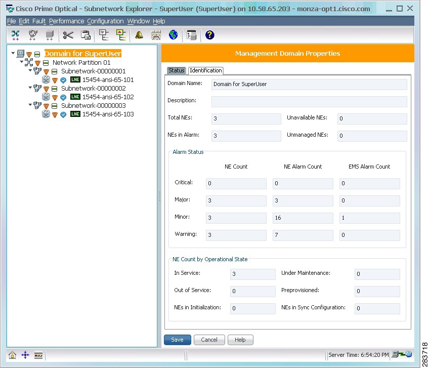
1.5.3 Subnetwork Explorer
The Subnetwork Explorer window displays a hierarchical view of all the network partitions, subnetworks, and NEs currently being monitored by Prime Optical. The alarm status is also indicated.
Figure 1-4 Subnetwork Explorer
The Subnetwork Explorer window is divided into two sections: the explorer tree and the properties pane. The explorer tree consists of a management domain, network partitions, subnetworks, and NEs, which are displayed in a hierarchical format. You can drag and drop NEs to reposition them in the tree. The properties pane on the right side of the window shows detailed information about the object that is selected in the tree.
The Subnetwork Explorer allows you to:
•
•
•
•
•
•
The Subnetwork Explorer has two modes: automatic and manual. In automatic mode, all topologically connected NEs are grouped automatically into subnetworks. You cannot associate NEs to subnetworks in this mode. In manual mode, you can associate NEs to subnetworks. To change the subnetwork mode, choose Administration > Control Panel > UI Properties and check or uncheck the Automatically Group NEs in Subnetworks check box.
In the transition period during which this option is being changed, any current operations (such as dropping an NE in a subnetwork) are completed.
The server time is displayed on the lower right side of the Subnetwork Explorer window. The server name is displayed in the window's title bar.
The Subnetwork Explorer has four properties panes: Management Domain Properties, Network Partition Properties, Subnetwork Properties, and Network Element Properties.
1.5.3.1 Management Domain Properties
See Management Domain Properties.
1.5.3.2 Network Partition Properties
See Group Properties and Network Partition Properties.
1.5.3.3 Subnetwork Properties
The Subnetwork Properties pane displays information about the subnetwork that is currently selected in the explorer tree. Click the expand icon next to a subnetwork in the tree to view the NEs that have been assigned to that subnetwork.
The Subnetwork Properties pane has two tabs: Status and Identification.
1.5.3.3.1 Status Tab
The following table describes the Status tab fields.
1.5.3.3.2 Identification Tab
The following table describes the fields in the Identification tab.
Note
Note
1.5.3.4 Network Element Properties
See Network Element Properties.
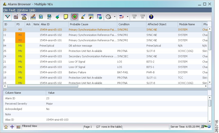
1.5.4 Alarm Browser
The Alarm Browser displays standing alarms and conditions in the managed domain that are assigned a severity level of critical, major, minor, or warning. It also shows cleared alarms that are not acknowledged.
Figure 1-5 Alarm Browser
Tip
Note
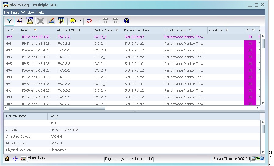
1.5.5 Alarm Log
The Alarm Log window contains alarms that have transitioned from the Alarm Browser. Cleared alarms are transitioned when you acknowledge them or when automatic acknowledgment has been enabled (in the Control Panel > UI Properties pane). In addition, the Alarm Log shows a history of cleared and acknowledged alarms and all transient conditions (also known as events or autonomous nonalarmed messages), as well as threshold crossing alerts (TCAs).
Figure 1-6 Alarm Log
Tip
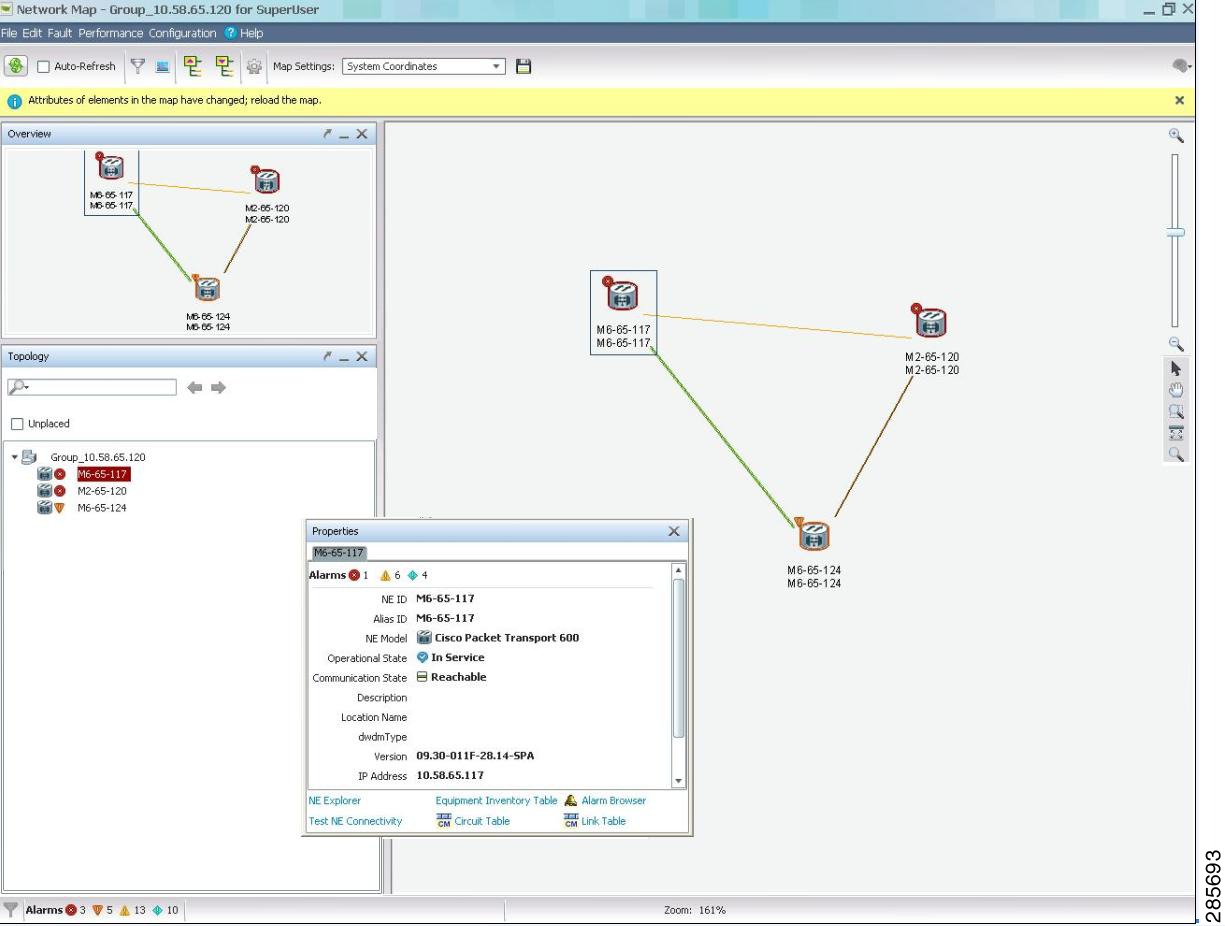
1.5.6 Network Map
The Network Map window allows you to graphically display how the network is partitioned.
Figure 1-7 Network Map
The Network Map is organized into a multilevel hierarchy that corresponds to the structure of the Domain Explorer tree. The Network Map hierarchy consists of management domains, groups, and NEs, which are displayed graphically.
Note
When you launch the Network Map from the Prime Optical domain, it displays a map with individual groups, NEs, and link icons. The network map has four main components—a center pane displaying the map image, Topology pane, Properties pane, and Overview pane. From the Topology pane, you can perform a search for NEs based on certain parameters. Prime Optical also allows you to filter network maps by NEs, groups, or links. For details, see How Do I Use Network Maps?.
Clicking Show Parent Network Map returns you to the parent map. When you launch the Network Map from a particular group in the Domain Explorer, the Network Map opens with the contents of the group displayed. After you zoom in on a region on the map, the pan tool at the right side of the screen allows you to pan the view to a different region. All groups are shown on a single map, and the zoom level and pan position determine which groups are visible at any time. You can open multiple map windows to compare different views.
All groups, NEs, links, and labels are zoomed when you zoom in or zoom out. Prime Optical allows you to save the zoom level and framing of the map.
With the Auto-Refresh check box selected in the Network Map window, a refreshed map is automatically displayed when:
•
•
•
•
•
•
•
•
When the Auto-Refresh check box is unchecked, a notification bar appears at the top of the network map window stating that attributes of elements in the map have changed, and you can click the Refresh tool to reload the map.
You can export a Network Map as an image in PNG format using the Export tool in the Network Map window.
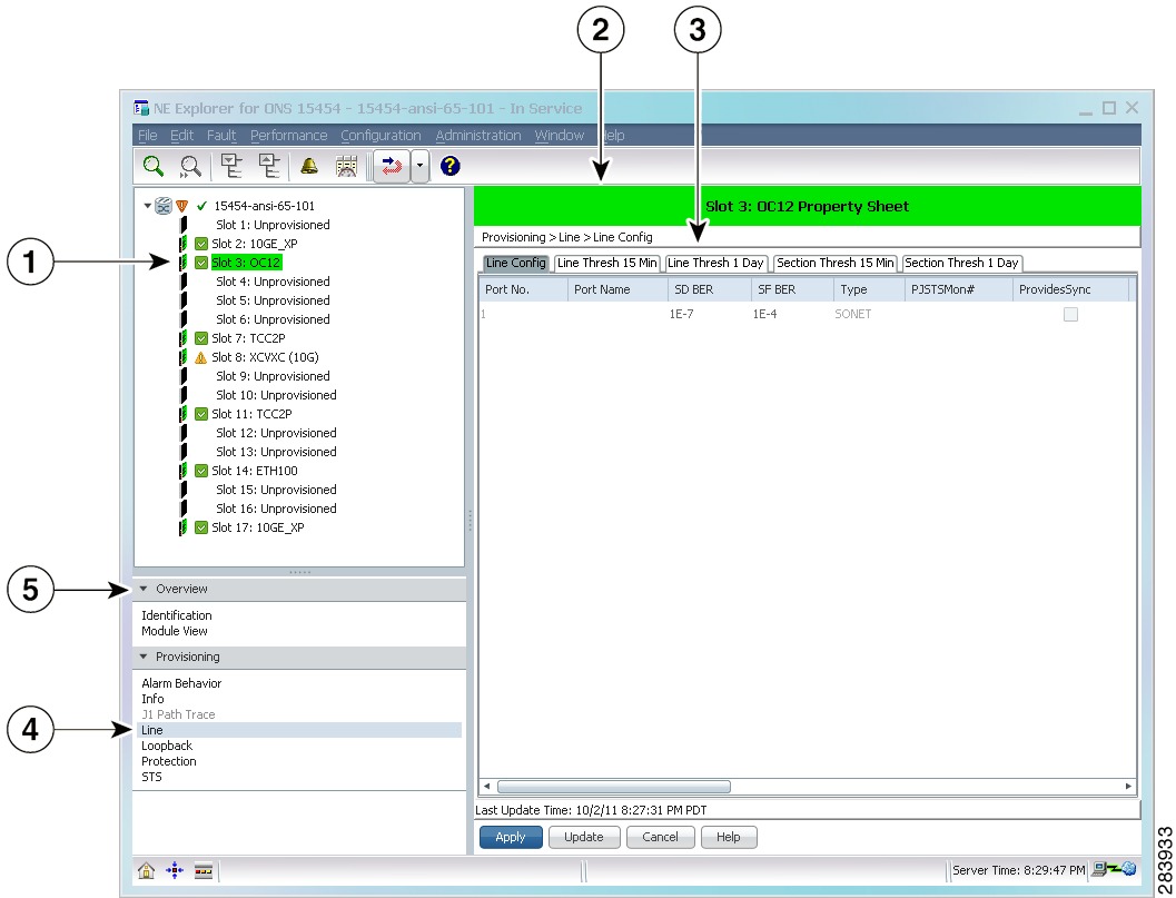
1.5.7 NE Explorer
The NE Explorer window shows service and equipment provisioning information about the selected NE. The configuration information is retrieved through the CLI, CORBA, SNMP, and TL1. The actual protocol used depends on the NE type.
Use one of the following methods to open the NE Explorer:
•
•
•
•
•
•
Figure 1-8 NE Explorer
To display all the slots under the node, click the expand icon (+) next to the node in the topology tree. To view properties, select the node or slot and click the down arrow next to the Overview and Provisioning drawers. Unavailable properties are dimmed.
When you change the data in the property sheet and try to navigate to a different node or slot property without saving, the following message appears.
Property sheet has been changed. Do you really want to discard changes?The following table lists the NEs supported in Prime Optical and describes the NE Explorer for each NE. Not all NEs have an associated NE Explorer.
Usage Notes:
•
Also, if you use the Create button to commit information on the NE, any changes to the value governed by the Apply button will be lost if they have not already been applied. For example, if you check the Allow SNMP Set check box on the SNMP tab, then create a trap destination host before clicking the Apply button, the check box will revert back to unchecked after the create operation is completed and the screen refreshes with the new trap destination in the table.
•
•
•
1.5.8 Control Panel
The Control Panel allows you to view and modify certain client and server configuration parameters. Certain modifications take effect immediately and change the active server configuration. Other changes take effect when the server is restarted.
The left side of the window displays the tree, which contains the different Prime Optical functions and services. The right side of the window displays the properties pane that corresponds to the selected client or server component.
Figure 1-9 Control Panel
Click the expand icon next to the Prime Optical functions and services in the tree structure to display the services contained within. For example, expand NE Service to display the individual services.
The following table describes the panes in the Control Panel.
1.6 General Features of Prime Optical
This section describes some of the general Prime Optical features.
Note
1.6.1 Window Views
All Prime Optical window views have a menu bar, toolbar, and status bar as described in the following table.
Note
1.6.2 Table Views
All Prime Optical table views share common characteristics, as described in the following table.
Table 1-17 Prime Optical Table Views
Page Back and Page Forward
Some tables return large numbers of rows. To support large tables, Prime Optical provides a paging feature. If more than 1000 rows of data are returned, data is grouped in pages of up to 1000 rows. You can page forward and page back to view the entire set of data.
•
•
Split-Pane View
—
Table views have two panes: a top pane and a bottom pane. The top pane displays the rows in the table. The bottom pane displays a detailed description of the selected row in the top pane. The bottom pane improves the readability of row attributes that might be truncated in the top pane. You can resize these panes by dragging the splitter bar up or down.
Note
Rearrange and Resize Columns
—
To rearrange columns in any table, select and drag the column title. To resize columns, drag the column separator line to the left or the right.
Note
Customize View
You can customize the way tables are displayed by selecting the columns to be displayed, and the order in which to display them. Prime Optical allows you to save your customized table view so that the next time you open the table, it is displayed in the same manner in which it was saved. See Customizing Table Views for more information.
Sort
—
You can sort columns using the up or down arrows. The up arrow represents ascending order; the down arrow represents descending order. The orange-colored arrow identifies the column that is the primary key in the current sort. To sort the data, simply click the column title.
Note
Group
—
You can group items in a column that have the same value using the square icons located in the column title. To group column items, simply click the column title. The color of the square icon turns orange, indicating that the column is grouped.
Note
Filter
Click the Filter tool to filter the data according to criteria that you select, and then display the results in a table. Some tables have a time-based Filter tool that allows you to filter data for the past 4 hours, past 8 hours, past 12 hours, past day, or past week.
Note
Export
Click the Export Data to File tool to export the tabular data to a file.
Note
HTML Report
Click the Generate HTML Report tool to generate an HTML report based on the data in the table. You can generate a report for selected rows or for all rows in the current page. A maximum of 1000 rows per page can be exported. After making your selection, click OK; the browser window appears with the HTML report. The report is saved automatically on the client system. (The default directory is C:\Cisco\TransportManagerClientversion-number\reports or /opt/CiscoTransportManagerClientversion-number/reports.) Use your browser's Print option to print the report.
1.6.3 Tree Views
All Prime Optical tree views share common characteristics, as described in the following table.
Table 1-18 Prime Optical Tree Views
Split-Pane View
—
Tree views have two panes: a left pane and a right pane. The left pane represents the topology tree; the right pane shows the properties of the entity selected in the tree.
Expand
Click the Expand tool (or choose Edit > Expand) to expand the selected tree node.
Collapse
Click the Collapse tool (or choose Edit > Collapse) to collapse the selected tree node.
Right-Click Options
—
Every selectable object has right-click options. Right-click a selectable object to view a shortcut menu that allows you to access more detailed information about the object.
1.6.4 Launching Context-Sensitive Information
Many Prime Optical views have a specific selection context, meaning that the same window will have a different look depending on where it was launched.
For example, if you launch the Alarm Browser from the management domain node, the browser shows all NE and EMS alarms (if you have permission to see EMS alarms). If you launch the Alarm Browser from a subnetwork, group, or NE node, the browser shows only NE alarms. If you launch the Alarm Browser from the Dashboard, the browser shows all NE alarms for the Prime Optical domain.
As another example, for circuit creation, the context of the launch point determines the choice of nodes that can be selected as source and destination nodes.
1.6.5 Finding Data
Prime Optical has a Find feature that you can use to locate specific data.
1.6.5.1 Finding Data in the Domain Explorer
In the Domain Explorer, you can use the Find dialog box to search for circuits, L2 topologies, NEs, or groups.
Step 1
Step 2
•
•
•
•
•
Note
Step 3
•
•
•
•
•
•
•
•
•
Tip
Step 4
•
•
•
•
Tip
Step 5
•
•
•
•
Tip
Tip
Step 6
Step 7
1.6.5.2 Finding Data in the NE Explorer
In the NE Explorer window, you can use the Find dialog box to search for a particular node or card by specifying the node or card name.
Step 1
Step 2
Step 3
Tip
Step 4
Note
Step 5
1.6.5.3 Finding NEs or Groups in the Network Map
In the Network Map window, you can use the Find on Map dialog box to search for a particular NE or group. The Find on Map dialog box allows you to search for an NE or group by providing the full or partial identifier of the NE or group. The Find on Map dialog box searches for a matching NE or group in the map and, if one is found, selects it automatically.
For a group, the identifier is always the name. For an NE, the identifier is the name or the alias, depending on which of the two attributes is currently displayed in the map.
Step 1
Step 2
Step 3
Tip
Step 4
Step 5
Step 6
Tip
1.6.6 Filtering Data
Filter dialog boxes filter user-specified data. Many tables have Filter dialog boxes that enable you to filter data in different ways and display the results in a table. If the filter supports wildcards, you can enter a percentage character (%) as a wildcard character to support broader searches.
1.6.7 Exporting Data
Most tables support an export function to export the table contents to a flat file. The Export dialog box allows you to export data as comma-separated values (CSVs) or tab-separated values (TSVs), which are formats commonly used to import data into spreadsheet and database applications for further analysis and manipulation. You can also select a user-specified character as a separator.
To open the Export dialog box, click the Export Data to File tool (or choose File > Export) in a table. The following table describes the fields in the Export dialog box. After making your selections, click OK.
Table 1-19 Field Descriptions for the Export Dialog Box
Comma separated
If selected, the data is exported as comma-separated values.
Tab separated
If selected, the data is exported as tab-separated values.
Other
If selected, the data is exported with the separator that you specify in the Other text field.
Note
Selected row(s)
If selected, only the selected rows in the current page are exported.
All rows in current page
If selected, all rows in the current page are exported.
Entire table
If selected, exports the entire contents of the selected table to a text file. A progress bar tracks the export progress.
The entire-table export writes the data to a user-specified text file and retains the user-selected table customizations. For example, if you customized the table to make a column invisible, that column does not appear in the exported file.
In the User Preferences dialog box, you can enable or disable the ability to export the entire Alarm Browser or Alarm Log. (You cannot enable or disable the ability to export the entire contents of the selected PM or inventory table.)
Note
Export Data to File
By default, exported data is stored in the C:\Cisco\TransportManagerClientversion-number\exports or /opt/CiscoTransportManagerClientversion-number/exports directory under the name that you provide in the Export Data to File text box. Click Browse to change the file location.
1.6.8 Exporting Alarms and Events
In addition to exporting directly from the Alarm Browser or the Alarm Log, Prime Optical provides an Event Export Manager window (Fault > Event Export Manager) that allows you to export alarms and events as they occur to the file of your choice. You can also set various parameters to refine the export. You can choose to export events continuously or to export a specific number of events.
•
•
Figure 1-10 Start and Stop Export Tools
The following table describes the fields in the Event Export Manager window.
Table 1-20 Field Descriptions for the Event Export Manager
Network Elements
Allows you to export alarms (NE alarms and Prime Optical-specific EMS alarms) and events for selected NEs. Choose from the list of available NEs and add them to the Selected list. If you have the appropriate user permission and you want to export EMS alarms and events, check the Export Prime Optical EMS Alarms/Events check box.
Severity
Allows you to export events that have a severity of Critical, Major, Minor, Warning, Indeterminate, and/or Cleared.
Export To
Allows you to export the file to a given destination. Click Browse to browse for a particular destination. You can also overwrite or append the file.
Export Options
Allows you to specify the field separator type. Types include Comma, Tab, Semicolon, or Other, an option you use to specify a different separator. You can also check the Stop export when check box and enter a number of records to instruct the Event Export Manager to stop exporting after logging the specified number of records.
1.6.9 Customizing Table Views
Most tables support a customized view function that allows you to select the columns to be displayed, and the order in which to display them. Prime Optical allows you to save your customized table view so that the next time you open the table, it is displayed in the same manner in which it was saved.
Step 1
Step 2
Step 3
Step 4
Note
Step 5
After you save the custom view:
•
•
•
Table 1-21 Field Descriptions for the Customize View Dialog Box
Add >
Select a column to display and click Add to move the column to the list of displayed columns.
< Remove
Select a column to hide and click Remove to move the column to the list of hidden columns.
Up/Down
Select a column from the list of columns to be displayed (at the right side). Click Up to reposition the selected column one place at a time to the left of the table, or click Down to reposition the selected column one place at a time to the right of the table.
TipApply
Click Apply to apply your customizations to the current session.
Cancel
Click Cancel to close the Customize View dialog box without applying any changes.
Help
Click Help to launch the online help.
1.6.10 Refreshing Data
Many windows have a Refresh Data toolbar icon that refreshes all data being displayed by Prime Optical. There are two versions of the Refresh Data tools, and both refresh data from either the server or the database:
•
•
Figure 1-11 Refresh Data Tool
Note
Note
•
1.6.11 Pruning the Database
Prime Optical automatically prunes various categories of data that tend to accumulate over time and would otherwise exhaust the available disk space. You can configure the following categories of data for automatic pruning:
•
•
•
•
•
•
•
The following options are provided to control the pruning for each category of data:
•
•
•
1.6.12 Using Mnemonics
All menus and menu options have a uniquely assigned mnemonic to support keyboard access to menu items in addition to access through the mouse. The underlined letter within a menu item indicates the mnemonic keystroke. For example, to exit the Prime Optical application, enter Alt+f (for the File menu); then, enter x (Exit).
1.6.13 Using the Online Help
The online help provides a detailed explanation of each Prime Optical GUI window and dialog box.
To view the online help for any window, you have two options:
•
•
Figure 1-12 Help Tool
To view the online help for any dialog box, click the Help button within the dialog box.
Tip
1.6.14 Using the Pin Tool
The Dashboard has a pin tool. When you click it, the window is pinned down, meaning that it is not brought to the foreground by default. If you click the pin tool again, the Dashboard window is pinned up, meaning that it is brought to the foreground each time an update occurs (alarm counts change, NE count changes, and so on).
1.6.15 Viewing System Details
To view the system details, complete the following steps:
Step 1
Step 2
•
•
•
•
•
•
•
•
1.6.16 Viewing Licensing (NE Audit) Information
Prime Optical allows you to view Licensing (NE Audit) information such as version summary and details grouped by device type, number of devices, and so on. Users with the appropriate role can generate, view, and export reports.
To view and export NE Audit information, complete the following steps:
Step 1
The device software version summary and the device type count report information are displayed.
•
•
•
•
•
Step 2
The list of all devices is displayed with the following fields:
•
•
•
•
•
–
–
–
–
–
–
•
•
•
Step 3
1.6.17 Action Buttons
The following table describes the actions that you can perform using the buttons at the bottom of Prime Optical windows and dialog boxes.
Table 1-22 Action Buttons
Add >
Click to select one or more available options; then, click Add > to add the selected option(s) to the list of selected options.
Note
Apply
Commits any changes to user-defined fields to the Prime Optical database and applies the changes to the NE.
Back
Returns to the previous screen. (In the first screen, Back is not available.)
Cancel
Replaces any changes to user-defined fields with the previous values. If the current window is a wizard, the wizard closes when you click the Cancel button.
Close
Closes the window.
Finish
Creates the service and closes the wizard.
Help
Launches the online help for the window.
Maximize
Click the Maximize button to expand the window. After you expand the window, the Maximize button changes to a Reset Size button.
Next
Temporarily saves the current information and displays the next screen. (In the last screen, Next is replaced by Finish.)
OK
Commits the selections made in the window and closes the window.
< Remove
Click to select one or more options; then, click < Remove to remove the selected option(s) and return them to the Available list.
Note
Reset
Resets the values displayed in the window to the default values.
Reset Size
Click the Reset Size button to return the window to its original size.
Save
Commits any changes to user-defined fields to the Prime Optical database and applies the changes to the NE.
Unlock
Unlocks the Prime Optical session and displays the Domain Explorer.
Update
Retrieves all current configuration settings for the selected NE. The time stamp Last Update Time: date time indicates the last time the configuration settings were retrieved for the NE. Any changes to user-defined fields that have not been applied are not updated with the fields' current configuration settings for the selected NE.
1.7 Related Documentation
This section summarizes the Prime Optical documentation and related documentation.
1.7.1 Prime Optical Documentation Set
Note
The Prime Optical documentation set comprises the following guides:
•
•
•
•
•
•
Note
•
•
1.7.2 Related Cisco NE Documentation
The following table lists the related NE hardware documentation.
Table 1-23 Related Cisco NE Documentation
•
•
•
•
•
•
•
•
•
•
•
•
•
•
•
•
•
•
•
•
•
•
•
•
•
•
•
•
•
•
•
•
•
•
•
•
•
•
•
•
•
•
•
•
•
•
•
•
•
•
•
•
•
•
•
•
•
•
•
•
•
•
•
•
•
•
•
•
•
•
•
•
•
•
•
•
•
•
•
•
•
•
•
•
•
•
•
•
•
The following related documentation can be used for reference:
•
•
•
•
•
•
•
•
•
•
•
•
•
•
•
•
•
•
•
•
•
•
•
•
•
•
•