Table Of Contents
NE Explorer Information
B.1 ONS 15216 NE Explorer
B.1.1 Active ONS 15216 NEs
B.1.2 Passive ONS 15216 NEs
B.1.3 ONS 15216 Passive DCU NE Explorer
B.1.4 ONS 15216 DWDM NE Explorer
B.1.5 ONS 15216 FlexLayer NE Explorer
B.1.6 ONS 15216 Passive EDFA NE Explorer
B.1.7 ONS 15216 Active EDFA2 NE Explorer
B.1.8 ONS 15216 Active EDFA3 NE Explorer
B.1.9 ONS 15216 Active OADM NE Explorer
B.1.10 ONS 15216 Passive OADM NE Explorer
B.1.11 ONS 15216 OSC Passive NE Explorer
B.2 ONS 15305
B.3 ONS 15305 CTC NE Explorer
B.3.1 Node Properties Pane—ONS 15305 CTC
B.4 ONS 15310 CL NE Explorer
B.4.1 Node Properties Pane—ONS 15310 CL
B.5 ONS 15310 MA SONET NE Explorer
B.5.1 Node Properties Pane—ONS 15310 MA SONET
B.6 ONS 15310 MA SDH NE Explorer
B.6.1 Node Properties Pane—ONS 15310 MA SDH
B.7 ONS 15327 NE Explorer
B.7.1 Node Properties Pane—ONS 15327
B.8 ONS 15454 MSTP NE Explorer
B.8.1 Node Properties Pane—ONS 15454 MSTP
B.8.2 Rack Properties Pane—ONS 15454 MSTP
B.8.3 Shelf Properties Pane—ONS 15454 MSTP
B.9 ONS 15454 SONET NE Explorer
B.9.1 Node Properties Pane—ONS 15454 SONET
B.10 ONS 15454 SDH NE Explorer
B.10.1 Node Properties Pane—ONS 15454 SDH
B.11 ONS 15454-M6 NE Explorer
B.11.1 Node Properties Pane—ONS 15454-M6
B.12 ONS 15454-M2 NE Explorer
B.12.1 Node Properties Pane—ONS 15454-M2
B.13 ONS 15600 SONET NE Explorer
B.13.1 Node Properties Pane—ONS 15600 SONET
B.14 ONS 15600 SDH NE Explorer
B.14.1 Node Properties Pane—ONS 15600 SDH
B.15 CPT 200 NE Explorer
B.16 CPT 600 NE Explorer
B.17 Unmanaged NE/Other Vendor Node Properties Pane
B.17.1 Identification
NE Explorer Information
This appendix provides information on the various NE Explorer windows supported in Cisco Prime Optical. This appendix contains the following sections:
• ONS 15216 NE Explorer
•ONS 15305
•ONS 15305 CTC NE Explorer
•ONS 15310 CL NE Explorer
•ONS 15310 MA SONET NE Explorer
•ONS 15310 MA SDH NE Explorer
•ONS 15327 NE Explorer
•ONS 15454 MSTP NE Explorer
•ONS 15454 SONET NE Explorer
•ONS 15454 SDH NE Explorer
•ONS 15454-M6 NE Explorer
•ONS 15454-M2 NE Explorer
•ONS 15600 SONET NE Explorer
•ONS 15600 SDH NE Explorer
•CPT 200 NE Explorer
•CPT 600 NE Explorer
•Unmanaged NE/Other Vendor Node Properties Pane
Note In the Prime Optical GUI, display-only fields have a gray background.
B.1 ONS 15216 NE Explorer
The NE Explorer for the ONS 15216 displays information about the selected ONS 15216 NE. ONS 15216 NEs are grouped as active NEs or passive NEs. Passive NEs do not have a management interface, so there is no communication between Prime Optical and passive ONS 15216 NEs. For passive ONS 15216 NEs, the NE Explorer summarizes NE information that has been entered manually through the Domain Explorer and also allows you to specify the serial number. For active ONS 15216 NEs, the NE Explorer allows you to view the actual values of settings and parameters on the NE and modify configurable parameters.
Table B-1 ONS 15216 NEs
Active ONS 15216 NEs
|
Passive ONS 15216 NEs
|
ONS 15216 100-GHz OADM
|
ONS 15216 EDFA1
|
ONS 15216 EDFA2
|
ONS 15216 200-GHz OADM
|
ONS 15216 EDFA3
|
ONS 15216 100-GHz DWDM Filters
|
ONS 15216 200-GHz DWDM Filters
|
ONS 15216 OSC
|
ONS 15216 DCU
|
ONS 15216 FlexLayer
|
B.1.1 Active ONS 15216 NEs
The Network Element Properties pane for active ONS 15216 NEs displays information specific to the active ONS 15216 erbium-doped fiber amplifier (EDFA) and optical add/drop multiplexer (OADM) NEs. The properties pane contains the following slot properties:
•Status
•Identification
•Address
•NE Authentication
The following table lists the different types of active ONS 15216 NEs.
Table B-2 List of Active ONS 15216 NE Types and Descriptions
Active ONS 15216 Types
|
Description
|
EDFA
|
Active EDFA with an IP address.
|
OADM
|
Active 100-GHz OADM with an IP address. The OADM can be a 1-, 2-, or 4-channel OADM.
|
B.1.1.1 Status
The Status Properties pane displays status information for the active NE.
Table B-3 Field Descriptions for the Status Properties Pane
Field
|
Description
|
NE ID
|
Displays the user-defined name of the selected NE.
|
Description
|
Displays information that a user has entered (if any) to describe the NE.
|
NE Model
|
Identifies the model of the selected ONS 15216 NE.
|
Alarm Status
|
Displays the total number of critical, major, minor, and warning alarms currently existing on the selected NE.
|
Communication State
|
Displays the current connectivity state between Prime Optical and the selected NE. Values are Available or Unavailable.
|
Operational State
|
Displays the current operational state of the selected NE and allows you to change the state. Values are In Service, Out of Service, and Under Maintenance.
|
B.1.1.2 Identification
The Identification Properties pane displays NE identification information.
Table B-4 Field Descriptions for the Identification Properties Pane
Field
|
Description
|
NE ID
|
Displays the user-defined name of the selected NE.
|
Description
|
Displays information that user has entered (if any) to describe the NE.
|
NE Model
|
Identifies the model of the selected ONS 15216 NE.
|
NE Type
|
Displays the ONS 15216 NE type.
|
Vendor Name
|
Displays the vendor name. The default vendor name is Cisco Systems.
|
Software Version
|
Displays the NE software version.
|
Version Name
|
Displays the name of the software version.
|
Location Name
|
Displays the geographic location of the selected NE.
|
B.1.1.3 Address
The Address Properties pane provides address information for the NE. If you change an address, the NE is reset automatically to make the new address selection valid.
Table B-5 Field Descriptions for the Address Properties Pane
Field
|
Description
|
NE ID
|
Displays the user-defined name of the selected NE.
|
Description
|
Displays information that a user has entered (if any) to describe the NE.
|
NE Model
|
Identifies the model of the selected ONS 15216 NE.
|
Active IP Address
|
Displays the IP address of the selected NE.
|
SNMP Community String
|
Displays the configured community string name used in Simple Network Management Protocol (SNMP) messages. The community name is used to determine whether a user has access to the device.
|
GNE ID
|
Displays the ID for the gateway NE (GNE) on the selected NE ring.
|
Subnetwork ID
|
Displays the name of the subnetwork associated with the selected NE.
|
Network Partition ID
|
Displays the name of the network partition associated with the selected NE.
|
B.1.1.4 NE Authentication
The NE Authentication Properties pane allows you to specify usernames and passwords for Prime Optical server connections to ONS 15216 NEs. Fields shown depend on the type of NE selected.
Table B-6 Field Descriptions for the NE Authentication Properties Pane
Field
|
Description
|
NE Connection
|
Username
|
Specify the username that the Prime Optical server uses to connect to ONS 15216 NEs.
|
Password
|
Specify the password to use for Prime Optical server-to-NE connections.
|
Confirm Password
|
Retype the password to confirm it.
|
Note Regardless of the actual length of the password, the Password and Confirm Password fields display only a fixed-length string of 15 asterisks (*).
Note See Table 1-22 for descriptions of actions that you can perform using the buttons at the bottom of the window.
B.1.2 Passive ONS 15216 NEs
The Network Element Properties pane for passive ONS 15216 NEs displays information specific to the passive EDFA, the passive OADM, the DCU, the OSC, and the DWDM ONS 15216 NEs. The passive ONS 15216 properties pane contains an Identification.
The following table lists the different types of passive ONS 15216 NEs.
Table B-7 List of Passive ONS 15216 NE Types and Descriptions
Passive ONS 15216 Types
|
Description
|
EDFA
|
Passive EDFA with no IP address or connectivity.
|
OADM
|
Passive 200-GHz OADM with no IP address or connectivity. The OADM can be either a 1- or 2-channel OADM.
|
DCU
|
Passive DCU with no IP address or connectivity.
|
OSC
|
Passive OSC with no IP address or connectivity.
|
DWDM
|
Passive DWDM filter with no IP address or connectivity. The DWDM filter can be a red, 200-GHz, DWDM filter; a blue, 200-GHz, DWDM filter; a red, 100-GHz, DWDM filter; or a blue, 100-GHz, DWDM filter.
|
B.1.2.1 Identification
The Identification Properties pane displays the NE identification information.
Table B-8 Field Descriptions for the Identification Properties Pane
Field
|
Description
|
NE ID
|
Displays the user-defined name of the selected NE.
|
Description
|
Displays information that a user has entered (if any) to describe the NE.
|
NE Model
|
Identifies the model of the selected NE (ONS 15216).
|
NE Type
|
Displays the ONS 15216 NE type.
|
Vendor Name
|
Displays the vendor name. The default vendor name is Cisco Systems.
|
Version Name
|
Displays the name of the software version.
|
Location Name
|
Displays the geographic location of the selected NE.
|
Operational State
|
Displays the current operational state of the system: In Service, Under Maintenance, or Out of Service.
|
Subnetwork ID
|
Displays the name of the subnetwork associated with the selected NE.
|
Note See Table 1-22 for descriptions of actions that you can perform using the buttons at the bottom of the window.
B.1.3 ONS 15216 Passive DCU NE Explorer
The ONS 15216 Passive DCU NE Explorer displays information about the ONS 15216 Passive DCU NE. It contains Identification, Slot 1, and Slot 2 Properties panes. (See Figure B-1.)
Each slot can accommodate any one of the following modules:
•DCU-100 (100 ps/nm)
•DCU-350 (350 ps/nm)
•DCU-450 (450 ps/nm)
•DCU-550 (550 ps/nm)
•DCU-750 (750 ps/nm)
•DCU-950 (950 ps/nm)
•DCU-1150 (1150 ps/nm)
•DCU-E-200 (200 ps/nm, ELEAF type)
•DCU-E-350 (350 ps/nm, ELEAF type)
•DCU-L-300 (300 ps/nm)
•DCU-L-600 (600 ps/nm)
•DCU-L-700 (700 ps/nm)
•DCU-L-800 (800 ps/nm)
•DCU-L-1000 (1000 ps/nm)
•DCU-L-1100 (1100 ps/nm)
•DCU-DS-L-100 (100 ps/nm)
•DCU-DS-L-200 (200 ps/nm)
•DCU-DS-L-300 (300 ps/nm)
•15216-FBGDCU-165 (165 ps/nm)
•15216-FBGDCU-331 (331 ps/nm)
•15216-FBGDCU-496 (496 ps/nm)
•15216-FBGDCU-661 (661 ps/nm)
•15216-FBGDCU-826 (826 ps/nm)
•15216-FBGDCU-992 (992 ps/nm)
•15216-FBGDCU-1157 (1157 ps/nm)
•15216-FBGDCU-1322 (1322 ps/nm)
•15216-FBGDCU-1653 (1653 ps/nm)
•15216-FBGDCU-1983 (1983 ps/nm)
B.1.3.1 Identification
The Identification Properties pane displays identification information for the ONS 15216 DCU NE.
Table B-9 Field Descriptions for the Identification Properties Pane
Field
|
Description
|
NE ID
|
Displays the ID of the NE from the Domain Explorer.
|
Description
|
Displays the description of the NE from the Domain Explorer.
|
NE Model
|
Displays the NE model type.
|
NE Type
|
Displays the type of NE.
|
NE Version
|
Displays the software version of the NE.
|
Product Name
|
Displays the name of the product.
|
CLEI Code
|
Displays the CLEI code.
|
Serial Number
|
Displays the serial number of the NE.
|
Location Name
|
Displays the name of the location where the NE is installed.
|
Subnetwork ID
|
Displays the ID of the subnetwork to which the NE belongs.
|
Network Partition ID
|
Displays the ID of the network partition.
|
B.1.3.2 Slot 1 and Slot 2
The Slot 1 and Slot 2 Properties panes display information about the first and second slots. The fields in both Properties panes are identical, except that they pertain to different slots.
Table B-10 Field Descriptions for the Slot 1 and Slot 2 Properties
Field
|
Description
|
Module Type
|
Displays the NE model type. Select one of the following module types:
•DCU-100 (100 ps/nm)
•DCU-350 (350 ps/nm)
•DCU-450 (450 ps/nm)
•DCU-550 (550 ps/nm)
•DCU-750 (750 ps/nm)
•DCU-950 (950 ps/nm)
•DCU-1150 (1150 ps/nm)
•DCU-E-200 (200 ps/nm, ELEAF type)
•DCU-E-350 (350 ps/nm, ELEAF type)
•DCU-L-300 (300 ps/nm)
•DCU-L-600 (600 ps/nm)
•DCU-L-700 (700 ps/nm)
•DCU-L-800 (800 ps/nm)
•DCU-L-1000 (1000 ps/nm)
•DCU-L-1100 (1100 ps/nm)
•DCU-DS-L-100 (100 ps/nm)
•DCU-DS-L-200 (200 ps/nm)
•DCU-DS-L-300 (300 ps/nm)
|
Product Name
|
Displays the name of the product.
|
CLEI Code
|
Displays the CLEI code.
|
Serial Number
|
Displays the serial number of the NE.
|
B.1.4 ONS 15216 DWDM NE Explorer
The NE Explorer for the ONS 15216 DWDM displays information about the passive ONS 15216 DWDM NE. It contains an Identification Properties pane.
The Cisco ONS 15216 48-channel muxponder/demuxponder unit is a new ONS 15216 FlexLayer unit that allows 48 channels of ITU wavelengths to be placed onto a single fiber, and removes 48 channels of ITU wavelengths from a single fiber.
R9.6 supports the ONS 15216 48-channel muxponder/demuxponder odd/even unit:
•15216-MD-48-ODD=: 48 channels spaced at 100 GHz on the Odd ITU grid
•15216-MD-48-EVEN=: 48 channels spaced at 100 GHz on the Even ITU grid
B.1.4.1 Identification
The Identification Properties pane displays identification information about the ONS 15216 DWDM NE. See the following table for field descriptions.
Table B-11 Field Descriptions for the Identification Properties Pane
Field
|
Description
|
NE ID
|
Displays the ID of the NE from the Domain Explorer.
|
Description
|
Displays the description of the NE from the Domain Explorer.
|
NE Model
|
Displays the NE model type.
|
NE Type
|
Displays the type of NE.
|
NE Version
|
Displays the software version of the NE.
|
Product Name
|
Displays the name of the product.
|
CLEI Code
|
Displays the Common Language Equipment Identification (CLEI) code.
|
Serial Number
|
Displays the serial number of the NE.
|
Location Name
|
Displays the name of the location where the NE is installed.
|
Subnetwork ID
|
Displays the ID of the subnetwork to which the NE belongs.
|
Network Partition ID
|
Displays the ID of the network partition.
|
B.1.5 ONS 15216 FlexLayer NE Explorer
The ONS 15216 FlexLayer NE Explorer displays information about the ONS 15216 FlexLayer NE. It contains the following Properties panes:
•Identification
•Slot 1 and Slot 2
B.1.5.1 Identification
The Identification Properties pane displays identification information about the ONS 15216 FlexLayer NE.
Table B-12 Field Descriptions for the Identification Properties Pane
Field
|
Description
|
NE ID
|
Displays the ID of the NE from the Domain Explorer.
|
Description
|
Displays the description of the NE from the Domain Explorer.
|
NE Model
|
Displays the NE model type.
|
NE Type
|
Displays the type of NE.
|
NE Version
|
Displays the software version of the NE.
|
Product Name
|
Displays the name of the product.
|
CLEI Code
|
Displays the CLEI code.
|
Serial Number
|
Displays the serial number of the NE.
|
Location Name
|
Displays the name of the location where the NE is installed.
|
Subnetwork ID
|
Displays the ID of the subnetwork to which the NE belongs.
|
Network Partition ID
|
Displays the ID of the network partition.
|
B.1.5.2 Slot 1 Through Slot 4
The Slot Properties panes show module information pertaining to the selected ONS 15216 FlexLayer NE slot. The fields in both Properties panes are identical, except that they pertain to different slots.
Table B-13 Field Descriptions for the Slot 1 through Slot 4 Properties
Field
|
Description
|
Module Type
|
Displays the type of module in the slot.
|
Product Name
|
Displays the name of the product.
|
CLEI Code
|
Displays the CLEI code.
|
Serial Number
|
Displays the serial number of the NE.
|
B.1.6 ONS 15216 Passive EDFA NE Explorer
The ONS 15216 Passive EDFA NE Explorer displays information about the ONS 15216 Passive EDFA NE. It contains an Identification Properties pane.
B.1.6.1 Identification
The Identification Properties pane displays identification information for the ONS 15216 Passive EDFA NE.
Table B-14 Field Descriptions for the Identification Properties Pane
Field
|
Description
|
NE ID
|
Displays the ID of the NE from the Domain Explorer.
|
Description
|
Displays the description of the NE from the Domain Explorer.
|
NE Model
|
Displays the NE model type.
|
NE Type
|
Displays the type of NE.
|
NE Version
|
Displays the software version of the NE.
|
Product Name
|
Displays the name of the product.
|
CLEI Code
|
Displays the CLEI code.
|
Serial Number
|
Displays the serial number of the NE.
|
Location Name
|
Displays the name of the location where the NE is installed.
|
Subnetwork ID
|
Displays the ID of the subnetwork to which the NE belongs.
|
Network Partition ID
|
Displays the ID of the network partition.
|
B.1.7 ONS 15216 Active EDFA2 NE Explorer
The ONS 15216 EDFA2 NE Explorer contains the following Properties panes, some of which apply only to a specific NE version:
•Identification
•Address
•Config/Status
•Diagnostics
•Thresholds
•Alarm Behavior
•SNMP
B.1.7.1 Identification
The Identification Properties pane displays identification information about the ONS 15216 EDFA2 NEs.
Table B-15 Field Descriptions for the Identification Properties Pane
Field
|
Description
|
NE ID
|
Displays the ID of the NE from the Domain Explorer.
|
Alias
|
Displays the alias name of the NE.
|
Description
|
Displays the description of the NE from the Domain Explorer.
|
NE Model
|
Displays the NE model type.
|
NE Type
|
Displays the type of NE.
|
NE Version
|
Displays the software version of the NE.
|
Wavelength(s)
|
Displays the number of wavelengths for the NE. This field is not applicable to the active EDFA NE type.
|
Product Name
|
Displays the name of the product.
|
CLEI Code
|
Displays the CLEI code.
|
Serial Number
|
Displays the serial number of the NE.
|
Location Name
|
Displays the name of the location where the NE is installed.
|
Location
|
Latitude
|
Allows you to set the latitude in the database. Select North or South from the drop-down list; then, enter the degrees and minutes (or click the up and down arrows to increase or decrease each by 1 unit).
|
Longitude
|
Allows you to set the longitude in the database. Select East or West from the drop-down list; then, enter the degrees and minutes (or click the up and down arrows to increase or decrease each by 1 unit).
|
Date and Time
|
Time
|
Displays the NE date and time.
|
Time Zone
|
Displays the time zone where the NE is located.
|
Use Daylight Savings Time
|
If checked, Daylight Savings Time is observed.
|
B.1.7.2 Address
The Address Properties pane displays information about the NE network address.
Table B-16 Field Descriptions for the Address Properties Pane
Field
|
Description
|
IP Address
|
Displays the IP address of the NE.
|
Subnet Mask
|
Displays the subnetwork mask ID of the NE.
|
Gateway Address
|
Displays the gateway address of the NE.
|
SNMP Community String
|
Displays the SNMP community string of the NE. You can edit this field.
|
GNE ID
|
Displays the GNE ID.
|
Subnetwork ID
|
Displays the ID of the subnetwork to which the NE belongs.
|
Network Partition ID
|
Displays the ID of the network partition.
|
B.1.7.3 Config/Status
The Config/Status Properties pane displays the configuration settings and status of the EDFA2.
Table B-17 Field Descriptions for the Config/Status Properties Pane
Field
|
Description
|
Overall
|
Overall Gain
|
Displays the value of the gain set point in dB when the mode is GAINTEMP (gets cerent15216EdfaConstGainOverallGainMeasured). Must be an integer from 13.0 to 22.0.
|
Measured Gain
|
Displays the measured overall gain in dB. The range is from 0.0 to 23.0.
Note If there is no input power, this field reports a negative (invalid) value.
|
Pre-Attenuation
|
Displays the gain preattenuation value in dB (gets cerent15216EdfaVariableGainPreAttenuationMeasured). Must be an integer from 0.0 to 11.0.
|
Input Power
|
Displays the EDFA2 input power. Must be an integer from -9999.99 to 9999.99.
|
Output Power
|
Displays the EDFA2 output power. Must be an integer from -999.99 to 999.99.
|
DC Power Bus Mode
|
Displays the power bus mode setting (Simplex or Duplex) and allows you to change the mode.
|
Auto Laser Shutdown
|
Allows you to enable (On) or disable (Off) auto laser shutdown for the EDFA2.
Note The auto laser shutdown feature is available for the ONS 15216 EDFA2 R2.4 and later.
|
Pump
|
Control Mode Setting
|
Displays the control mode of the laser pumps. Constant gain is achieved by using an automatic control circuit that adjusts pump power when changes in input power are detected. The ONS 15216 EDFA2 operates in Constant Gain Temperature Compensated mode by default, but since there might be applications where other operating modes are required, the ONS 15216 EDFA2 can be set to operate in any one the following pump control modes:
•Constant Gain Temperature Compensated mode (ConstGainTempComp; Cisco default).
•Constant Output Power mode (ConstOutputPower).
Note Pump 1 cannot be set to ConstOutputPower mode.
•Constant Pump Current mode (ConstCurrent).
•Constant Pump Power mode (ConstPower).
•Idle—Laser pumps can be shut down using the Idle control mode.
Caution Use the pump control modes Constant Output Power, Constant Pump Current, and Constant Pump Power with extreme caution. These modes are service affecting and can reduce the lifecycle of the lasers if used in extreme conditions. The factory default setting and the recommended mode of operation is Constant Gain Temperature Compensated mode. It is recommended that you contact the Cisco TAC before changing from this mode of operation.
|
Actual Control Mode
|
Displays the actual control mode of the laser pumps.
|
Constant Pump Current
|
Displays the laser pump constant pump current in milliamperes (mA). This is the current used when the control mode is changed to constCurrent. When changing Pump 1, Pump 2 is changed automatically when the Apply button is clicked.
|
Constant Pump Power
|
Displays the constant pump power in milliwatts (mW). The range is from 0 to 100 mW; the Cisco default is 0. You must set the constant power of pump 1 and pump 2 at the same time.
|
Constant Output Power
|
Displays the constant output power in mW. Only Pump2 is writeable. When ConstOutputPower is selected as the control mode, this field is enabled and editable for Pump2 and not for Pump1. The Const Power field is enabled with the Cisco default value (0). The range is from 0.0 to 65.0 mW.
|
B.1.7.4 Diagnostics
The Diagnostics Properties pane allows you to view NE laser pump attributes.
Table B-18 Field Descriptions for the Diagnostics Properties Pane
Field
|
Description
|
Gain Module Temp
|
Displays the gain module temperature in degrees Celsius. Must be an integer from -99.99 to 99.99.
|
Gain Module Volt
|
Displays the gain module voltage in volts. Must be an integer from 0 to 999.
|
Input Power
|
Displays the laser input power in dBm. Must be an integer from -9999.99 to 9999.99.
|
Output Power
|
Displays the laser output power in dBm. Must be an integer from -999.99 to 999.99.
|
Gain
|
Displays the laser gain in dB. Must be an integer from -999.9 to 999.9.
|
Pump
|
Chip Temp
|
Displays the chip temperature in degrees Celsius. Must be an integer from -999.9 to 999.9.
|
Chip Temp Set Pt.
|
Displays the chip temperature set point in degrees Celsius. Must be an integer from 0.0 to 99.9.
|
TEC Current
|
Displays the TEC current in mA. Must be an integer from 0 to 99999.
|
Current
|
Displays the laser current in mA. Must be an integer from 0 to 999.
|
Power
|
Displays the pump power in mW. Must be an integer from 0.0 to 999.99.
|
B.1.7.5 Thresholds
The Thresholds Properties pane displays the threshold settings of the EDFA2.
Table B-19 Field Descriptions for the Thresholds Properties Pane
Field
|
Description
|
Input Power
|
Threshold
|
Displays the input power threshold value in dBm. Must be an integer from -31 to -15.
|
Hysteresis
|
Displays the input power hysteresis value in dB. Must be an integer from 0 to 10.
|
Input Power
|
Displays the input power threshold value. Must be an integer from -9999.99 to 9999.99.
|
Output Power
|
Alm Deviation
|
Displays the output power alarm deviation value in dB. Must be an integer from 0 to 10.
|
Alm Hysteresis
|
Displays the output power alarm hysteresis value in dB. Must be an integer from 0 to 10.
|
Output Power Setpt
|
Displays the output power setpoint threshold value.
|
Gain
|
Min Gain
|
Displays the minimum gain setting. Must be an integer from -999.99 to 999.99.
|
Max Gain
|
Displays the maximum gain setting. Must be an integer from -999.99 to 999.99.
|
Measured Gain
|
Displays the value of the gain in dB when the mode is GAINTEMP (gets cerent15216EdfaConstGainOverallGainMeasured). Must be an integer from 0 to 23.
|
Gain Module Temperature
|
Min Temperature
|
Displays the minimum case temperature in degrees Celsius. Must be an integer from -10 to 10.
|
Max Temperature
|
Displays the maximum case temperature in degrees Celsius. Must be an integer from 20 to 70.
|
Min Hysteresis
|
Displays the minimum case temperature hysteresis in degrees Celsius. Must be an integer from 0 to 10.
|
Max Hysteresis
|
Displays the maximum case temperature hysteresis in degrees Celsius. Must be an integer from 0 to 10.
|
Power Bus
|
Power Bus Min
|
Displays the minimum allowable power bus DC voltage. Must be an integer from -70 to -35.
|
Power Bus Max
|
Displays the maximum allowable power bus DC voltage. Must be an integer from -70 to -35.
|
Laser 1 Current
|
Out-of-Range
|
Displays the Laser 1 pump temperature that is out of range.
|
Current
|
Displays the current of the Laser 1 pump in mA.
|
Laser 2 Current
|
Out-of-Range
|
Displays the Laser 2 pump temperature that is out of range.
|
Current
|
Displays the current of the Laser 2 pump in mA.
|
Laser 1 Temperature
|
Temp Min
|
Displays the minimum temperature of Laser 1.
|
Temp Max
|
Displays the maximum temperature of Laser 1.
|
Chip Temp
|
Displays the Laser 1 chip temperature in degrees Celsius. Must be an integer from -999.99 to 999.99.
|
Laser 2 Temperature
|
Temp Min
|
Displays the minimum temperature of Laser 2.
|
Temp Max
|
Displays the maximum temperature of Laser 2.
|
Chip Temp
|
Displays the Laser 2 chip temperature in degrees Celsius. Must be an integer from -999.99 to 999.99.
|
B.1.7.6 Alarm Behavior
The Alarm Behavior Properties pane allows you to enter, save, view, and update NE fault management attributes.
Table B-20 Field Descriptions for the Alarm Behavior Properties Pane
Field
|
Description
|
Probable Cause
|
Displays the probable cause of the alarm.
|
Severity
|
Displays the alarm severity (Critical, Major, Minor, Informational, or Not Alarmed).
Note If two minor power bus alarms are generated, the second alarm is escalated to critical in the Alarm Browser window. If the alarm severity is changed to another value, the alarm remains critical due to the power bus escalation feature, which overrides the alarm severity provisioning for power bus alarms.
|
B.1.7.7 SNMP
The SNMP Properties pane displays the settings for the SNMP Community table, the Trap Destination table, and SNMP views. The SNMP Properties pane contains the following tabs: SNMP Community Table, Trap Destination Table, and SNMP Views.
Table B-21 Field Descriptions for the SNMP Properties Pane
Field
|
Description
|
SNMP Community Table
|
Community Name
|
Displays the SNMP community name.
|
View Index
|
Displays the view index that specifies which MIBs that the community string can access.
|
Privileges
|
Displays the bitmap of access privilege that govern what management operations a particular community can perform. These privileges are expressed as a sum of values, where each value represents a particular operation. The decimal values and their respective SNMP operation are:
•1—Get
•2—GetNext
•4—Response (enabled for all community strings)
•8—Set
•16—SNMPv1-Trap
•32—GetBulk
•64—Inform (enabled for all community strings)
•128—SNMPv2-Trap (enabled for all community strings)
For example, 255 is the sum of all decimal values and specifies access to all SNMP operations. This sum is the default private community. 247 is the sum for all SNMP operations with the exception of the Set operation. This sum is the default public community.
Use the buttons in the Privileges column to set privilege values. In the Privilege Editor dialog box, check the check boxes that correspond to the privileges that you want to set. After making your selections, click OK. Prime Optical computes the bit value automatically.
|
IP Address
|
Displays the source IP address.
|
Subnet Mask
|
Displays the subnet mask for the source IP address.
|
Status
|
Displays the community string status. Values are:
•Active
•Not in Service
•Not Ready
•Create and Go
•Create and Wait
•Destroy
|
Trap Destination Table
|
IP Address
|
Displays the trap destination IP address.
|
UDP Port
|
Displays the trap destination UDP port.
|
Community Name
|
Displays the trap destination community string.
|
Version
|
Displays the trap version number.
|
View Index
|
Displays the trap destination MIB view index.
|
Status
|
Displays the community string status. Values are:
•Active
•Not in Service
•Not ready
•Create and Go
•Create and Wait
•Destroy
|
SNMP Trap Enable check box
|
If checked, allows you to enable SNMP traps on the NE.
Note This is a global setting, meaning all users are affected by a change to this setting.
|
SNMP Views
|
View Index
|
Displays the view index number, which is a unique value for each MIB view.
|
Subtree
|
Displays an object identifier that designates a subtree element in the MIB hierarchy.
|
Mask
|
Displays a bit mask that identifies objects in the subtree.
|
Type
|
Displays a flag that specifies the status of the view. Valid entries are included and excluded.
|
Status
|
Indicates the status of the SNMP view entry. If the entry currently exists, the status is active.
|

Note See Table 1-22 for descriptions of actions that you can perform using the buttons at the bottom of the window.
B.1.8 ONS 15216 Active EDFA3 NE Explorer
The ONS 15216 EDFA3 NE Explorer contains the following Properties panes:
•Identification
•Address
•Config/Status
•Diagnostics
•Thresholds
•Alarm Behavior
•SNMP
B.1.8.1 Identification
The Identification Properties pane displays identification information for the ONS 15216 EDFA3 NE.
Table B-22 Field Descriptions for the Identification Properties Pane
Field
|
Description
|
NE ID
|
Displays the ID of the NE from the Domain Explorer.
|
Description
|
Displays the description of the NE from the Domain Explorer.
|
NE Model
|
Displays the NE model type.
|
NE Type
|
Displays the type of NE.
|
NE Version
|
Displays the software version of the NE.
|
Wavelength(s)
|
Displays the number of wavelengths for the NE. This field is not applicable to the active EDFA NE type.
|
Product Name
|
Displays the name of the product.
|
CLEI Code
|
Displays the CLEI code.
|
Serial Number
|
Displays the serial number of the NE.
|
Location Name
|
Displays the name of the location where the NE is installed.
|
NE Date and Time
|
Displays the date and time configured on the NE.
|
Location
|
Latitude
|
Allows you to set the latitude of the NE. Select North or South from the drop-down list; then, enter the degrees and minutes (or click the up and down arrows to increase or decrease each by 1 unit).
|
Longitude
|
Allows you to set the longitude of the NE. Select East or West from the drop-down list; then, enter the degrees and minutes (or click the up and down arrows to increase or decrease each by 1 unit).
|
B.1.8.2 Address
The Address Properties pane displays information about the NE network address.
Table B-23 Field Descriptions for the Address Properties Pane
Field
|
Description
|
IP Address
|
Displays the IP address of the NE.
|
Subnet Mask
|
Displays the subnetwork mask ID of the NE.
|
Gateway Address
|
Displays the gateway address of the NE.
|
SNMP Community String
|
Displays the SNMP community string of the NE. You can edit this field.
|
MAC Address
|
Displays the ONS 15216 EDFA3 address as it is identified on the IEEE 802 MAC layer.
|
GNE ID
|
Displays the GNE ID.
|
Subnetwork ID
|
Displays the ID of the subnetwork to which the NE belongs.
|
Network Partition ID
|
Displays the ID of the network partition.
|
B.1.8.3 Config/Status
The Config/Status Properties pane displays the configuration settings and status of the EDFA3 and lasers.
Table B-24 Field Descriptions for the Config/Status Properties Pane
Field
|
Description
|
Control Mode
|
Control Mode
|
Displays the amplifier control mode. Values are:
•Constant Output Power
•Constant Gain (Cisco default)
|
Gain
|
Gain
|
Displays the gain value. Values are integers from 0 to 40 dB.
|
Gain Setpoint
|
Displays the gain setpoint. The range is from 5.0 to 38.5 dB; the Cisco default is 21 dB.
|
Power
|
Laser 1 Output Power
|
Displays the amplifier output power related to laser 1. The range is from -60 to 25 dBm.
|
Power Setpoint
|
Displays the amplifier output power setpoint value. The range is from -7 to 17 dBm; the Cisco default is 10 dBm.
|
Amplifier Input Power
|
Displays the amplifier input power. The range is from -60 to 25 dBm.
|
Laser 2 Input Power
|
Displays the mid-stage access input power value related to laser 2. The range is from -60 to 25 dBm.
|
Amplifier Output Power
|
Displays the mid-stage access output power value. The range is from -60 to 25 dBm.
|
Power Offset
|
Displays the output power offset. The range is from -20 to 20 dBm; the Cisco default is 0.
|
Tilt
|
Tilt
|
Displays the tilt value. The range is from -15 to 15 dB.
|
Tilt Setpoint
|
Displays the tilt setpoint. The range is from -15 to 15 dB; the Cisco default is 0 dB.
|
Tilt Offset
|
Displays the tilt offset. The range is from -20 to 20 dB; the Cisco default is 0 dB.
|
Laser
|
Laser Status
|
Displays the automatic laser shutdown (ALS) status. Values are:
•On—Lasers are on
•APR—Lasers are in the automatic power reduction state
•Off—Lasers are off
|
OSRI
|
Displays the OSRI. Values are:
•On—Laser switch is locked on
•Off—(Cisco default) There is no lock on the lasers
|
DC Power Bus Mode
|
DC Power Bus Mode
|
Displays the power bus mode: Simplex or Duplex.
|
B.1.8.4 Diagnostics
The Diagnostics Properties pane displays diagnostics information for the EDFA3 and lasers.
Table B-25 Field Descriptions for the Diagnostics Properties Pane
Field
|
Description
|
DCU Insertion Loss
|
Displays the insertion loss of the DCU inserted in mid-stage. The range is from 0 to 20 dB.
|
VOA Value
|
Displays the variable optical attenuator (VOA) value. The range is from -100 to 100 dB.
|
Laser Bias
|
Laser 1 Bias
|
Displays the laser 1 bias. The range is from 0 to 150 mA.
|
Laser 2 Bias
|
Displays the laser 2 bias. The range is from 0 to 150 mA.
|
Temperatures
|
Case Temperature
|
Displays the case temperature. The range is from -100 to 150 degrees Celsius.
|
Fiber Temperature
|
Displays the fiber temperature. The range is from -100 to 150 degrees Celsius.
|
Pump 1 Temperature
|
Displays the pump 1 temperature. The range is from -100 to 150 degrees Celsius.
|
Pump 2 Temperature
|
Displays the pump 2 temperature. The range is from -100 to 150 degrees Celsius.
|
Bus Voltages
|
Bus A Voltage
|
Displays the power bus A voltage. The range is from 0 to 999 V.
|
Bus B Voltage
|
Displays the power bus B voltage. The range is from 0 to 999 V.
|
B.1.8.5 Thresholds
The Thresholds Properties pane displays the threshold settings of the EDFA3.
Table B-26 Field Descriptions for the Thresholds Properties Pane
Field
|
Description
|
Gain
|
Degrade High
|
Displays the degrade high threshold associated with the amplifier gain. The range is from 0 to 40 dB.
|
Degrade Low
|
Displays the degrade low threshold associated with the amplifier gain. The range is from 0 to 40 dB.
|
Gain
|
Displays the gain value. The range is from 0 to 40 dB.
|
Line 1 Tx Power
|
Degrade High
|
Displays the degrade high threshold associated with the amplifier output power related to the Line 1 Tx port. The range is from 0 to 40 dB.
|
Degrade Low
|
Displays the degrade low threshold associated with the amplifier output power related to the Line 1 Tx port. The range is from 0 to 40 dB.
|
Line 1 Output Power
|
Displays the amplifier output power related to the Line 1 Tx port. The range is from -60 to 25 dBm.
|
Fail Low
|
Displays the fail low threshold associated with the output power value related to the Line 1 Tx port. The range is from -10 to 14 dBm; the Cisco default is -6 dBm.
|
Line 1 Rx Power
|
Amplifier Input Power
|
Displays the amplifier input power value related to the Line 1 Rx port. The range is from -60 to 25 dBm.
|
Fail Low
|
Displays the fail low threshold associated with the input power value related to the Line 1 Rx port. The range is from -49 to 13 dBm; the Cisco default is 10 dBm.
|
Line 2 Rx Power
|
Laser 2 Input Power
|
Displays the mid-stage access input power value related to the Line 1 Rx port. The range is from -60 to 25 dBm.
|
Fail Low
|
Displays the fail low threshold associated with the mid-stage access input power related to the Line 2 Rx port. The range is from -49 to 15 dBm; the Cisco default is -33 dBm.
|
Gain Module Temperature
|
Temperature Max
|
Displays the maximum allowable case temperature threshold. The range is from 60 to 100 degrees Celsius; the Cisco default is 65 degrees Celsius.
|
Temperature Min
|
Displays the minimum allowable case temperature threshold. The range is from -10 to 30 degrees Celsius; the Cisco default is -5 degrees Celsius.
|
Case Temperature
|
Displays the case temperature. The range is from -100 to 150.
|
Bus Voltage
|
Bus Voltage Max
|
Displays the power bus A and B maximum voltage. The range is from 49 to 70 V; the Cisco default is 57 V.
|
Bus Voltage Min
|
Displays the power bus A and B minimum voltage. The range is from 0 to 47 V; the Cisco default is 40 V.
|
Bus A Voltage
|
Displays the power bus A voltage. The range is from 0.0 to 999.9 V.
|
Bus B Voltage
|
Displays the power bus B voltage. The range is from 0.0 to 999.9 V.
|
B.1.8.6 Alarm Behavior
The Alarm Behavior Properties pane allows you to enter, save, view, and update NE fault management attributes.
Table B-27 Field Descriptions for the Alarm Behavior Properties Pane
Field
|
Description
|
Probable Cause
|
Displays the possible causes of the alarm.
|
Severity
|
Displays the alarm severity (Critical, Major, Minor, or Not Alarmed) and whether the alarm is service affecting (SA) or nonservice affecting (NSA).
|
B.1.8.7 SNMP
The SNMP Properties pane displays information about the SNMP Trap Destination table. Click Add Row to create a new trap destination; click Delete Row to delete an existing trap destination.
Table B-28 Field Descriptions for the SNMP Properties Pane
Field
|
Description
|
IP Address
|
Displays the SNMP IP address.
|
UDP Port Number
|
Displays the trap destination UDP port.
|
Community Name
|
Displays the trap destination community name.
|
Version
|
Displays the SNMP version number.
|
Note See Table 1-22 for descriptions of actions that you can perform using the buttons at the bottom of the window.
B.1.9 ONS 15216 Active OADM NE Explorer
The ONS 15216 OADM NE Explorer displays information about the ONS 15216 100-GHz OADM NE.
The ONS 15216 100-GHz OADM NE Explorer contains the following Properties panes:
•Identification
•Address
•DWDM
•Alarms
•Thresholds
B.1.9.1 Identification
The Identification Properties pane displays identification information for the ONS 15216 100-GHz OADM NE.
Table B-29 Field Descriptions for the Identification Properties Pane
Field
|
Description
|
NE ID
|
Displays the ID of the NE from the Domain Explorer.
|
Description
|
Displays the description of the NE from the Domain Explorer.
|
NE Model
|
Displays the NE model type.
|
NE Type
|
Displays the type of NE.
|
NE Version
|
Displays the software version of the NE.
|
Wavelength(s)
|
Displays the number of wavelengths for this NE.
|
Product Name
|
Displays the name of the product.
|
CLEI Code
|
Displays the CLEI code.
|
Serial Number
|
Displays the serial number of the NE.
|
Location Name
|
Displays the name of the location where the NE is installed.
|
NE Date and Time
|
Displays the date and time when the NE was installed.
|
B.1.9.2 Address
The Address Properties pane displays information about the NE network address.
Table B-30 Field Descriptions for the Address Properties Pane
Field
|
Description
|
IP Address
|
Displays the IP address of the NE.
|
Subnet Mask
|
Displays the subnetwork mask ID of the NE. If the field does not apply to the NE, the label is grayed out and the value reads Not Applicable.
|
Gateway Address
|
Displays the gateway address of the NE. If the field does not apply to the NE, the label is grayed out and the value reads Not Applicable.
|
SNMP Community String
|
Displays the SNMP community string of the NE. If the field does not apply to the NE, the label is grayed out and the value reads Not Applicable.
|
GNE ID
|
Displays the GNE ID.
|
Subnetwork ID
|
Displays the ID of the subnetwork to which the NE belongs.
|
Network Partition ID
|
Displays the ID of the network partition associated with the selected NE.
|
B.1.9.3 DWDM
The DWDM Properties pane allows you to view, enter, update, and save the NE DWDM attributes.
Table B-31 Field Descriptions for the DWDM Properties Pane
Field
|
Description
|
Channel Number
|
Displays the channels that can be added or dropped. Values are:
•1-channel—West 1, East 1
•2-channel—West 1, East 1, West 2, East 2
•4-channel—West 1, East 1, West 2, East 2, West 3, East 3, West 4, East 4
|
Mode
|
Allows you to configure the NE DWDM mode. Values are:
•Setpoint (Cisco default)—The add channel power is set to the value of the Default Add Channel Power. Although the Default Add Channel Power can be set in any configuration, the add channel power is only equal to the Default Add Channel Power value in this mode.
•Off—To turn off an add channel, set the channel power to a very low value (for example, -35 dBm). No alarm will be triggered.
•Disable—When an add/drop channel is not in use, the channel should be configured in DISBABLE mode where no alarms will be triggered.
|
Default Add Channel Power
|
Displays the default power of the added channel in dBm. It is available only if you select Setpoint as the mode. Values must be from -29.0 to 3.0 in increments of 0.1.
|
InsLossAdd
|
Shows the calculated insertion loss for the add channel.
|
InsLossDrop
|
Shows the calculated insertion loss for the drop channel.
|
InsLossXpress
|
Shows the calculated insertion loss for the express/through channels.
|
Calculated Setpoint (CALCSETP)
|
The CALCSETP feature of the ONS 15216 OADM is a calculated value, and represents the OADMs recommended optical power level setting for a particular add channel. Following this recommendation when selecting the setpoint value for a particular add channel will allow the composite outgoing signal (composed of express channels and newly added channels) to be as flat as possible. The formula used for this calculation is CALCSETP = PWRDROP + ILDROP - ILTHRU.
|
Passive Cards
|
Provides information about passive units provisioned in CTC.
Note Passive units can be provisioned in CTC only.
|
B.1.9.4 Alarms
The Alarms Properties pane allows you to enter, save, view, and update NE dropped-channel, signal-loss alarm attributes.
Table B-32 Field Descriptions for the Alarms Properties Pane
Field
|
Description
|
Channel Number
|
Displays the channels that can be added or dropped. Values are:
•1-channel—West 1, East 1
•2-channel—West 1, East 1, West 2, East 2
•4-channel—West 1, East 1, West 2, East 2, West 3, East 3, West 4, East 4
|
Drop Channel Signal Loss Alarm
|
Displays the current condition of the drop channel signal loss alarm. Values are:
•On—Enables the loss signal alarm of the drop channel.
•Off—Disables the loss signal alarm of the drop channel.
|
B.1.9.5 Thresholds
The Thresholds Properties pane allows you to enter, save, view, and update NE loss-of-signal and add/drop channel-signal mismatch threshold attributes.
Table B-33 Field Descriptions for the Thresholds Properties Pane
Field
|
Description
|
Channel Number
|
Displays the channels that can be added or dropped. Values are:
•1-channel—West 1, East 1
•2-channel—West 1, East 1, West 2, East 2
•4-channel—West 1, East 1, West 2, East 2, West 3, East 3, West 4, East 4
|
Loss of Signal
|
Displays the signal loss threshold value. Valid values are -30.0 to 3.5 dBm in increments of 0.1 dBm.
|
Drop and Add Signal Mismatch
|
Displays the threshold value for the drop channel signal loss alarm. Valid values are 0.2 to 2.0 dB in increments of 0.1 dB. The Cisco default is 1.0 dB.
|
Note See Table 1-22 for descriptions of actions that you can perform using the buttons at the bottom of the window.
B.1.10 ONS 15216 Passive OADM NE Explorer
The ONS 15216 Passive OADM NE Explorer displays information about the ONS 15216 passive OADM NE. It contains an Identification Properties pane.
B.1.10.1 Identification
The Identification Properties pane displays identification information for the ONS 15216 passive OADM NE.
Table B-34 Field Descriptions for the Identification Properties Pane
Field
|
Description
|
NE ID
|
Displays the ID of the NE from the Domain Explorer.
|
Description
|
Displays the description of the NE from the Domain Explorer.
|
NE Model
|
Displays the NE model type.
|
NE Type
|
Displays the type of NE.
|
NE Version
|
Displays the software version of the NE.
|
Wavelength(s)
|
Displays the number of wavelengths for this NE.
|
Product Name
|
Displays the name of the product. Displays 15216-MD16-2-BLUE for the blue version and 15216-MD16-2-RED for the red version. Displays Unknown if the product name is not known.
Note The information displayed in the Product Name field depends on the wavelength selected.
|
CLEI Code
|
Displays the CLEI code. Displays WMMFD00BRA for the blue version and WMMFE00BRA for the red version. Displays Unknown if the CLEI code is not known.
Note The information displayed in the CLEI Code field depends on the wavelength selected.
|
Serial Number
|
Displays the serial number of the NE. You can edit this field.
|
Location Name
|
Displays the name of the location where the NE is installed. You can edit this field.
|
Subnetwork ID
|
Displays the ID of the subnetwork to which the NE belongs.
|
Network Partition ID
|
Displays the ID of the network partition to which the NE belongs.
|
Note See Table 1-22 for descriptions of actions that you can perform using the buttons at the bottom of the window.
B.1.11 ONS 15216 OSC Passive NE Explorer
The ONS 15216 Passive OSC NE Explorer displays information about the ONS 15216 passive OSC NE. It contains an Identification Properties pane.
B.1.11.1 Identification
The Identification Properties pane displays the identification information for the ONS 15216 passive OSC NE.
Table B-35 Field Descriptions for the Identification Properties Pane
Field
|
Description
|
NE ID
|
Displays the ID of the NE from the Domain Explorer.
|
Description
|
Displays the description of the NE from the Domain Explorer.
|
NE Model
|
Displays the NE model type.
|
NE Type
|
Displays the type of NE.
|
NE Version
|
Displays the software version of the NE.
|
Wavelength(s)
|
Displays the number of wavelengths for this NE.
|
Product Name
|
Displays the name of the product.
|
CLEI Code
|
Displays the CLEI code.
|
Serial Number
|
Displays the serial number of the NE. You can edit this field.
|
Location Name
|
Displays the name of the location where the NE is installed. You can edit this field.
|
Subnetwork ID
|
Displays the ID of the subnetwork to which the NE belongs.
|
Network Partition ID
|
Displays the ID of the network partition.
|
Note See Table 1-22 for descriptions of actions that you can perform using the buttons at the bottom of the window.
B.2 ONS 15305
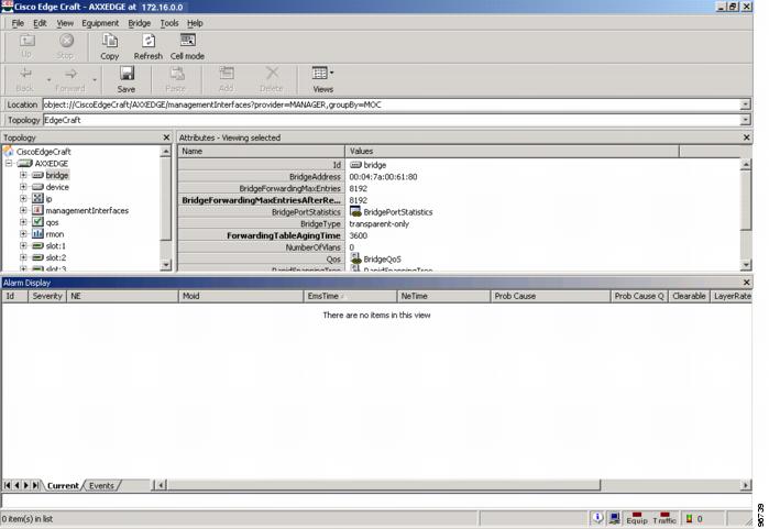
The NE Explorer is not available for the ONS 15305. You can get equivalent functionality by launching Cisco Edge Craft from Prime Optical; choose Configuration > ONS 15305 > Launch Cisco Edge Craft.
Note Cisco Edge Craft is not supported on Windows 7 client machine.
Figure B-1 Cisco Edge Craft for the ONS 15305
B.3 ONS 15305 CTC NE Explorer
When you choose Configuration > NE Explorer for the ONS 15305, the window that Prime Optical displays consists of a tree on the left side and a Properties pane on the right. The tree provides a hierarchical view and alarm status of the NE's physical shelves and slots. The Properties pane shows information about the selected entity. See Node Properties Pane—ONS 15305 CTC for more information.
Note If CTC is launched from the web browser for an ONS 15305 node, the CTC GUI might look different from when it is launched from Prime Optical. This discrepancy occurs because the latest version of CTC (for NE releases supported by Prime Optical) is packaged with Prime Optical. If launched from a browser, the CTC software is retrieved from the NE itself, which might be a version different from that packaged with Prime Optical.
When an NE Explorer is in autorefresh mode, all values of an entity that is being edited by the user are automatically refreshed. You will lose all of your changes unless you click the Apply button. To enable autorefresh, click the Refresh Data button in the NE Explorer.
B.3.1 Node Properties Pane—ONS 15305 CTC
The node properties pane displays information about the ONS 15305 CTC slot that is selected in the NE Explorer tree. The properties pane contains the following properties, some of which apply only to a specific NE version:
•Shelf View
•Identification
•Network
•Protection
•DCC
•Alarm
B.3.1.1 Shelf View
The Shelf View Properties pane displays a graphic of the ONS 15305 CTC that is selected in the NE Explorer tree. Moving the mouse pointer over the graphic of the NE, its shelves, slots, or cards displays the current alarms for the highlighted item. Double-clicking a slot or card displays the slot or card in the properties pane. The right-click menu allows you to reset or delete the card. For unprovisioned slots, the right-click menu allows you to add a card.
B.3.1.2 Identification
The Identification Properties pane displays information about the NE.
Table B-36 Field Descriptions for the Identification Properties Pane
Field
|
Description
|
NE ID
|
Displays the ID of the NE from the Domain Explorer.
|
Description
|
Displays the description of the NE from the Domain Explorer.
|
NE Model
|
Displays the NE model type.
|
Software Version
|
Displays the current running version of the system software.
|
Contact
|
Displays the name of the node contact person and the phone number.
|
System Description
|
Displays a description of the NE.
|
TP Settings
|
Use TP Server
|
If checked, CTC uses a Simple Network Time Protocol (SNTP) server to set the date and time of the node. Using an SNTP server ensures that all ONS 15305 network nodes use the same date and time reference. The server synchronizes the node's time after power outages or software upgrades. If you check the Use TP Server check box, enter the server's IP address in the next field. If you do not use an SNTP server, complete the Time and Time Zone fields. The ONS 15305 CTC will use these fields for alarm dates and times.
|
TP Server
|
Displays the SNTP server IP address.
|
Location
|
Latitude
|
Allows you to set the latitude of the NE. Select North or South from the drop-down list; then, enter the degrees and minutes (or click the up and down arrows to increase or decrease each by 1 unit).
|
Longitude
|
Allows you to set the longitude of the NE. Select East or West from the drop-down list; then, enter the degrees and minutes (or click the up and down arrows to increase or decrease each by 1 unit).
|
Date and Time
|
Time
|
Displays the NE date and time.
|
Time Zone
|
Displays the time zone where the NE is located.
|
B.3.1.3 Network
The Network Properties pane displays information about the NE network address. The Network Properties pane contains the following tabs:
•Address Tab
•Static Routes Tab
•OSPF Tab
•SNMP Tab
B.3.1.3.1 Address Tab
The Address tab allows you to view and change information about the NE network address.
Table B-37 Field Descriptions for the Address Tab
Field
|
Description
|
IP Address
|
Displays the IP address of the NE.
|
Default Router
|
Displays the IP address of the default router.
|
Subnet Mask
|
Displays the subnetwork mask ID of the NE.
|
MAC Address
|
Displays the ONS 15305 address as it is identified on the IEEE 802 MAC layer.
|
B.3.1.3.2 Static Routes Tab
The Static Routes tab allows you to view information about Prime Optical and ONS 15305 CTC connectivity and create or delete static routes.
Table B-38 Field Descriptions for the Static Routes Tab
Field
|
Description
|
Destination IP
|
Displays the IP address of the computer running Prime Optical.
|
Subnet Mask
|
Displays the subnetwork mask.
|
Next Hop
|
Displays the IP address of the router port or the node IP address if the Prime Optical computer is connected to the node directly.
|
Cost
|
Displays the number of hops between the ONS 15305 CTC and the computer.
|
Route Type
|
Displays the type of route (Other, Reject, Local, or Remote).
|
Protocol
|
Displays the protocol (OSPF or RIP).
|
B.3.1.3.3 OSPF Tab
The OSPF tab displays Open Shortest Path First (OSPF) information. OSPF is a link-state Internet routing protocol.
Table B-39 Field Descriptions for the OSPF Tab
Field
|
Description
|
Slot
|
Displays the slot number.
|
Port
|
Displays the port number.
|
DCC OSPF Area ID
|
Displays the number that identifies the ONS 15305 CTCs as a unique OSPF area. The OSPF area number can be from 0.0.0.0 to 255.255.255.255. The number must be unique to the LAN OSPF area.
|
LAN Port Area ID
|
Displays the OSPF area ID for the router port where the ONS 15305 CTC is connected. (This number is different from the DCC OSPF area ID.)
|
Router Priority
|
Displays the designated router for a subnet.
|
Hello Interval
|
Displays the number of seconds between OSPF hello packet advertisements sent by OSPF routers. Ten seconds is the Cisco default.
|
Dead Interval
|
Displays the number of seconds that will pass while an OSPF router's packets are not visible before its neighbors declare the router down. Forty seconds is the Cisco default.
|
Transit Delay
|
Displays the service speed. One second is the Cisco default.
|
Retransmit Interval
|
Displays the time that will elapse before a packet is resent. Five seconds is the Cisco default.
|
LAN Metric
|
Displays a cost for sending packets across the LAN. This value should always be lower than the DCC metric. Ten is the Cisco default.
|
B.3.1.3.4 SNMP Tab
The SNMP tab allows you to view SNMP information and create or delete SNMP trap destinations.
Table B-40 Field Descriptions for the SNMP Tab
Field
|
Description
|
Allow SNMP Set
|
If checked, allows you to use SNMP management software with the ONS 15305 CTC.
|
IP Address
|
The IP address of the NMS.
|
Community Name
|
The SNMP community name.
Note The SNMP community string cannot be blank in Prime Optical.
|
UDP Port
|
The UDP port for SNMP. The Cisco default UDP port is 162.
|
Trap Version
|
The trap version, either SNMP version 1 or version 2. See your NMS documentation to determine whether to use SNMP version 1 or version 2.
|
Relay A IP Address
|
The first ONS 15305 CTC to relay traps through. The IP address is appended to the base community string to tell the first NE the IP address and the port to forward the trap to. The second NE recognizes the IP address and strips it from the community string before forwarding the trap.
|
Relay A Community Name
|
The community name for the relay A node to use in the trap when forwarding it.
|
Relay B IP Address
|
The second ONS 15305 CTC to relay traps through.
|
Relay B Community Name
|
The community name for the relay B node to use in the trap when forwarding it.
|
Relay C IP Address
|
The third ONS 15305 CTC to relay traps through.
|
Relay C Community Name
|
The community name for the relay C node to use in the trap when forwarding it.
|
B.3.1.4 Protection
The Protection Properties pane contains the following tabs:
•Protection Groups Tab
•Operations Tab
B.3.1.4.1 Protection Groups Tab
The Protection Groups tab displays a list of available protection groups and allows you to create, delete, and view protection groups.
Table B-41 Field Descriptions for the Protection Groups Tab
Field
|
Description
|
Protection Groups
|
Displays a list of available protection groups. Click the Create or Delete button to create a new protection group or delete an existing one.
|
Selected Protection Group
|
Name
|
Modify the name of the selected protection group. The name can have up to 32 alphanumeric characters.
|
Type
|
View the protection type (1:1 [card], 1:N [card], Y Cable [port], or 1+1 [port]) of the selected protection group.
|
Protect Module
|
View the protect module if using 1+1 protection.
|
Available Entities
|
Displays a list of available entities. You can toggle between available and working entities.
|
Working Entities
|
Displays a list of working entities. You can toggle between working and available entities.
|
Bidirectional Switching
|
Click if you want both the transmit and the receive channels to switch if a failure occurs on one. This option is available only if you select the 1+1 (port) type.
|
Revertive
|
If checked, the node reverts traffic to the working card or port after failure conditions for the amount of time entered in Reversion Time. This option is not available if you select the 1:N (card) type.
|
Reversion Time
|
If Revertive is checked, choose the amount of time following failure condition correction after which the node should switch back to the working card or port. Use half-minute increments. This option is available only if you select the 1:1 (card) type.
|
B.3.1.4.2 Operations Tab
The Operations tab displays the protection group operation information.
Table B-42 Field Descriptions for the Operations Tab
Field
|
Description
|
Protection Groups
|
Displays a list of available protection groups.
|
Protection Group Details
|
Displays details about the selected protection groups and allows you to execute switch commands.
|
Switch Commands
|
Allows you to perform a manual switch, perform a forced switch, or clear the existing command switching.
|
Inhibit Switching
|
Allows you to inhibit unlock switching, lock out switching, or lock on switching.
|
B.3.1.5 DCC
The DCC Properties pane allows you to configure the Data Communication Channel on the regeneration and multiplex sections.
Table B-43 Field Descriptions for the DCC Properties Pane
Field
|
Description
|
DccR
|
DCC-R Terminations
|
Displays the DCC termination on the regeneration section configured. The slot and port on which this type of termination is configured are displayed.
|
Admin State
|
Allows you to check and set the administrative state of the DCC termination. Values are In Service (IS) or Out of Service (OOS).
|
DccM
|
DCC-M Terminations
|
Displays the DCC termination on the multiplex section configured. The slot and port on which this type of termination is configured are displayed.
|
Admin State
|
Allows you to check and set the administrative state of the DCC termination. Values are IS or OOS.
|
B.3.1.6 Alarm
The Alarm Properties pane allows you to change default alarm severities by creating unique alarm profiles for individual nodes. The Alarm Properties pane contains the Alarm Behavior tab.
Note The Alarm Properties pane might contain default alarm profile entries for cards that are not supported by the ONS 15305 CTC. Therefore, you might see some alarms that do not apply to the NE type that you are provisioning.
B.3.1.6.1 Alarm Behavior Tab
The Alarm Behavior tab allows you to change default alarm severities by creating unique alarm profiles.
Table B-44 Field Descriptions for the Alarm Behavior Tab
Field
|
Description
|
Alarm Profile
|
Choose a global alarm profile for the NE from the drop-down list.
|
Suppress Alarms
|
If checked, all alarms are suppressed.
|
Slot Number
|
Displays the location of the module.
|
Equipment Type
|
Displays the type of module in the slot.
|
Profile
|
Choose an alarm profile for the slot from the drop-down list.
|
Suppress Alarms
|
Indicates whether or not the alarms for a particular card are suppressed. If checked, all alarms are suppressed for the port.
|
B.4 ONS 15310 CL NE Explorer
When you choose Configuration > NE Explorer for the ONS 15310 CL, the window that Prime Optical displays consists of a tree on the left side and a properties pane on the right. The tree provides a hierarchical view and alarm status of the NE's physical shelves and slots. The properties pane shows information about the selected entity. See Node Properties Pane—ONS 15310 CL for more information.
Note If CTC is launched from the web browser for an ONS 15310 CL node, the CTC GUI might look different from when it is launched from Prime Optical. This discrepancy occurs because the latest version of CTC (for NE releases supported by Prime Optical) is packaged with Prime Optical. If launched from a browser, the CTC software is retrieved from the NE itself, which might be a version different from that packaged with Prime Optical.
When an NE Explorer is in autorefresh mode, all values of an entity that is being edited by the user are automatically refreshed. You will lose all of your changes unless you click the Apply button. To enable autorefresh, click the Refresh Data button in the NE Explorer.
B.4.1 Node Properties Pane—ONS 15310 CL
The node properties pane displays information about the ONS 15310 CL slot that is selected in the NE Explorer tree. The properties pane contains the following tabs, some of which apply only to a specific NE version:
•Shelf View
•General
•Identification
•Network
•DCC
•Timing
•Protection
•NE Defaults
•Security
•Alarm
•XC Utilization
•OSI
B.4.1.1 Shelf View
The Shelf View Properties pane displays a graphic of the ONS 15310 CL that is selected in the NE Explorer tree. Moving the mouse pointer over the graphic of the NE, its shelves, slots, or cards displays the current alarms for the highlighted item. Double-clicking a slot or card displays the slot or card in the properties pane. The right-click menu allows you to reset or delete the card. For unprovisioned slots, the right-click menu allows you to add a card.
B.4.1.2 General
The General Properties pane displays identification information, voltage thresholds, and multishelf configurations for the ONS 15310 CL NE.
Table B-45 Field Descriptions for the General Properties Pane
Field
|
Description
|
Identification Tab
|
NE ID
|
Displays the ID of the NE from the Domain Explorer.
|
NE Model
|
Displays the NE model type.
|
Software Version
|
Displays the current running version of the system software.
|
Contact
|
Displays the name and phone number of the node contact person.
|
Description
|
Enter a description of the NE.
|
System Description
|
Displays the NE type and the version of the system software.
|
Voltage/Temperature Tab
|
Voltage
|
Displays the voltage (in millivolts) of the shelf that corresponds to the power supply.
|
Temperature
|
Displays the temperature (in degrees Celsius) of the shelf.
|
B.4.1.3 Identification
The Identification Properties pane displays information about the ONS 15310 CL NE.
Table B-46 Field Descriptions for the Identification Properties Pane
Field
|
Description
|
NE ID
|
Displays the ID of the NE from the Domain Explorer.
|
Description
|
Displays the description of the NE from the Domain Explorer.
|
NE Model
|
Displays the NE model type.
|
Software Version
|
Displays the current running version of the system software.
|
Contact
|
Displays the name of the node contact person and the phone number.
|
System Description
|
Displays a description of the NE.
|
SNTP Settings
|
Use NTP/SNTP Server
|
If checked, CTC uses a Simple Network Time Protocol (SNTP) server to set the date and time of the node. Using an SNTP server ensures that all ONS 15310 CL network nodes use the same date and time reference. The server synchronizes the node's time after power outages or software upgrades. If you check the Use NTP/SNTP Server check box, enter the server's IP address in the next field. If you do not use an SNTP server, complete the Time and Time Zone fields. The ONS 15310 CL will use these fields for alarm dates and times.
|
SNTP Server
|
Displays the SNTP server IP address.
|
Location
|
Latitude
|
Allows you to set the latitude of the NE. Select North or South from the drop-down list; then, enter the degrees and minutes (or click the up and down arrows to increase or decrease each by 1 unit).
|
Longitude
|
Allows you to set the longitude of the NE. Select East or West from the drop-down list; then, enter the degrees and minutes (or click the up and down arrows to increase or decrease each by 1 unit).
|
Date and Time
|
Time
|
Displays the NE date and time.
|
Time Zone
|
Displays the time zone where the NE is located.
|
Use Daylight Savings Time
|
If checked, Daylight Savings Time is observed.
|
AIS-V Insertion on STS-1 Signal Degrade - Path
|
Insert AIS-V on STS-1 SD-P
|
If checked, the NE inserts an AIS-V signal when it detects an STS-1 signal degrade.
|
SD-P BER
|
Select the signal degrade path bit error rate for AIS-V insertion.
|
B.4.1.4 Network
The Network Properties pane displays information about the NE network address. The Network Properties pane contains the following tabs:
•Address Tab
•Static Routes Tab
•OSPF Tab
•OSPF Area Range Tab
•OSPF Virtual Links Tab
•SNMP Tab
•Firewall/Proxy Tab
•RIP Routing Table Tab
•RIP Tab
•Routing Table Tab
•Proxy Tunnels Tab
•Firewall Tunnels Tab
•FTP Hosts Tab
B.4.1.4.1 Address Tab
The Address tab allows you to view and change information about the NE network address.
Table B-47 Field Descriptions for the Address Tab
Field
|
Description
|
IP Address
|
Displays the IP address of the NE.
|
Default Router
|
Displays the IP address of the default router.
|
Subnet Mask
|
Displays the subnetwork mask ID of the NE.
|
MAC Address
|
Displays the ONS 15310 CL address as it is identified on the IEEE 802 MAC layer.
|
Forward DHCP Requests
|
If checked, forwards Dynamic Host Configuration Protocol (DHCP) requests to the IP address entered in the DHCP Server field. When the Forward DHCP Requests check box is unchecked, the DHCP Server field is display-only.
|
DHCP Server
|
Displays the IP address of the DHCP server.
|
IPv6 Config
|
Enable IPv6
|
If checked, allows you to configure the node to use the IPv6 protocol and to assign an IPv6 address to the node.
|
IPv6 Address
|
Enter the IPv6 address of the node.
|
Default IPv6 Router
|
Enter the IPv6 default router of the node.
|
IPv6 Subnet Mask
|
Enter the IPv6 subnetwork mask length.
|
B.4.1.4.2 Static Routes Tab
The Static Routes tab allows you to view information about Prime Optical and ONS 15310 CL connectivity and create or delete static routes.
Table B-48 Field Descriptions for the Static Routes Tab
Field
|
Description
|
Destination IP
|
Displays the IP address of the computer running Prime Optical.
|
Subnet Mask
|
Displays the subnetwork mask.
|
Next Hop
|
Displays the IP address of the router port or the node IP address if the Prime Optical computer is connected to the node directly.
|
Cost
|
Displays the number of hops between the ONS 15310 CL and the computer.
|
B.4.1.4.3 OSPF Tab
The OSPF tab displays Open Shortest Path First (OSPF) information. OSPF is a link-state Internet routing protocol.
Table B-49 Field Descriptions for the OSPF Tab
Field
|
Description
|
Slot
|
Displays the slot number.
|
Port
|
Displays the port number.
|
DCC OSPF Area ID
|
Displays the number that identifies the ONS 15310 CL NE as a unique OSPF area. The OSPF area number can be from 0.0.0.0 to 255.255.255.255. The number must be unique to the LAN OSPF area.
|
SDCC Metric
|
Sets a cost for sending packets across the Section Data Communications Channel (SDCC), which is used by OSPF routers to calculate the shortest path. This value should always be higher than the LAN metric. The Cisco default metric is 100. This value is normally unchanged.
|
LDCC Metric
|
Sets a cost for sending packets across the Line Data Communications Channel (LDCC), which is used by OSPF routers to calculate the shortest path. This value should always be higher than the LAN metric. This value is normally unchanged.
|
OSPF on LAN
|
OSPF Active on LAN
|
If checked, enables ONS 15310 CL OSPF topology to be advertised to OSPF routers on the LAN. Enable this field on ONS 15310 CL NEs that directly connect to OSPF routers.
|
LAN Port Area ID
|
Displays the OSPF area ID for the router port where the ONS 15310 CL is connected. (This number is different from the DCC OSPF area ID.)
|
Router Priority
|
Displays the designated router for a subnet.
|
Dead Interval
|
Displays the number of seconds that will pass while an OSPF router's packets are not visible before its neighbors declare the router down. Forty seconds is the Cisco default.
|
Retransmit Interval
|
Displays the time that will elapse before a packet is resent. Five seconds is the Cisco default.
|
Hello Interval
|
Displays the number of seconds between OSPF hello packet advertisements sent by OSPF routers. Ten seconds is the Cisco default.
|
Transit Delay
|
Displays the service speed. One second is the Cisco default.
|
LAN Metric
|
Displays a cost for sending packets across the LAN. This value should always be lower than the DCC metric. Ten is the Cisco default.
|
OSPF Authentication
|
Authentication Type
|
Displays Simple Password if the router where the ONS 15310 CL is connected uses authentication. Otherwise, it displays No Authentication.
|
Authentication Key
|
Displays the OSPF key (password) if authentication is enabled.
|
Confirm Authentication Key
|
Retype the authentication key to confirm it.
|
B.4.1.4.4 OSPF Area Range Tab
The OSPF Area Range tab allows you to view information about OSPF area ranges and create or delete area ranges.
Table B-50 Field Descriptions for the OSPF Area Range Tab
Field
|
Description
|
Range Address
|
Displays the area IP address for the ONS 15310 CL NE that resides within the OSPF area.
For example, if the ONS 15310 CL OSPF area includes nodes with IP addresses 10.10.20.100, 10.10.30.150, 10.10.40.200, and 10.10.50.250, the range address would be 10.10.0.0.
|
Range Area ID
|
Displays the OSPF area ID for the ONS 15310 CL NEs. This is either the ID in the DCC OSPF Area ID field or the ID in the LAN Port Area ID field.
|
Mask Length
|
Displays the subnet mask length.
|
Mask
|
Displays the subnet mask IP address.
|
Advertise
|
Indicates whether the OSPF range table is advertised.
|
B.4.1.4.5 OSPF Virtual Links Tab
The OSPF Virtual Links tab allows you to view information about OSPF virtual links and create or delete virtual links.
Note You cannot create a new virtual link unless OSPF is active on the LAN.
Table B-51 Field Descriptions for the OSPF Virtual Links Tab
Field
|
Description
|
Neighbor
|
Displays the router ID of the Area 0 router.
|
Transit Delay (sec)
|
Displays the service speed. One second is the Cisco default.
|
Retransmit Interval (sec)
|
Displays the time that will elapse before a packet is resent. Five seconds is the Cisco default.
|
Hello Interval (sec)
|
Displays the number of seconds between OSPF hello packet advertisements sent by OSPF routers. Ten seconds is the Cisco default.
|
Dead Interval (sec)
|
Displays the number of seconds that will pass while the packets of an OSPF router are not visible before its neighbors declare the router down. Forty seconds is the Cisco default.
|
Authentication Type
|
Displays the authentication type.
|
Authentication Key
|
Displays the authentication key.
|
B.4.1.4.6 SNMP Tab
The SNMP tab allows you to view SNMP information and create or delete SNMP trap destinations.
Table B-52 Field Descriptions for the SNMP Tab
Field
|
Description
|
Allow SNMP Set
|
If checked, allows you to use SNMP management software with the ONS 15310 CL.
|
Allow SNMP Proxy
|
If checked, allows you to configure the ONS 15310 CL to proxy SNMP calls.
|
IP Address
|
The IP address of the NMS.
|
Community Name
|
The SNMP community name.
Note The SNMP community string cannot be blank in Prime Optical.
|
UDP Port
|
The UDP port for SNMP. The Cisco default UDP port is 162.
|
Trap Version
|
The trap version, either SNMP version 1 or version 2. See your NMS documentation to determine whether to use SNMP version 1 or version 2.
|
Relay A IP Address
|
The first ONS 15310 CL to relay traps through. The IP address is appended to the base community string to tell the first NE the IP address and the port to forward the trap to. The second NE recognizes the IP address and strips it from the community string before forwarding the trap.
|
Relay A Community Name
|
The community name for the relay A node to use in the trap when forwarding it.
|
Relay B IP Address
|
The second ONS 15310 CL to relay traps through.
|
Relay B Community Name
|
The community name for the relay B node to use in the trap when forwarding it.
|
Relay C IP Address
|
The third ONS 15310 CL to relay traps through.
|
Relay C Community Name
|
The community name for the relay C node to use in the trap when forwarding it.
|
B.4.1.4.7 Firewall/Proxy Tab
The Firewall/Proxy tab allows you to use an NE as a proxy server or as a firewall.
Table B-53 Field Descriptions for the Firewall/Proxy Tab
Field
|
Description
|
Gateway Settings
|
Enable Proxy Server on Port
|
If checked, the ONS 15310 CL serves as a proxy for connections between the Prime Optical server and ONS 15310s that are DCC-connected to the proxy ONS 15310 CL. The Prime Optical server establishes connections to DCC-connected nodes through the proxy node. The Prime Optical server can connect to nodes that it cannot directly reach from the host on which it runs. The proxy server port number (display-only) is shown following the Enable Proxy Server on Port field. The proxy server uses port 1080.
If checked, the following radio buttons are enabled:
•End Network Element (ENE)—Enables the ONS 15310 CL to proxy as an ENE. Note that an alternate expansion for ENE is external network element.
•Gateway Network Element (GNE)—Enables the ONS 15310 CL to proxy as a GNE.
•Proxy-only—Enables proxy only.
If unchecked, the node does not proxy.
|
B.4.1.4.8 RIP Routing Table Tab
The RIP Routing Table tab allows you to view the Routing Information Protocol (RIP) routing table.
Table B-54 Field Descriptions for the RIP Routing Table Tab
Field
|
Description
|
Destination
|
Displays the IP address of the destination network or host.
|
Mask
|
Displays the subnet mask used to reach the destination network or host.
|
Gateway
|
Displays the IP address of the gateway used to reach the destination network or host.
|
Cost
|
Displays the hop count metric. The valid range is from 1 to 15.
|
B.4.1.4.9 RIP Tab
The RIP tab allows you to view and configure RIP parameters.
Note•When you enable RIP, you must wait for approximately one minute for the default RIP address summary to become visible.
•When you disable RIP on the NE, all summary address entries in the Summary Address table are deleted.
Table B-55 Field Descriptions for the RIP Tab
Field
|
Description
|
RIP Active
|
Check this check box to enable RIP. Uncheck it to disable RIP.
Note Checking the RIP Active check box and clicking the Apply button does not enable RIP. Instead, you must check the RIP Active check box, click the Create button, and use the Create RIP Address Summary dialog box to create a new RIP address. For details, see Using RIP.
|
RIP Type
|
Select RIP version 1.0 or RIP version 2.0.
|
Metric
|
Enter the hop count metric. The valid range is from 1 to 15.
|
Authentication Type
|
Select the authentication type.
|
Authentication Key
|
Enter the authentication key (password) if the authentication type is Simple Password.
|
Confirm Authentication Key
|
Retype the authentication key to confirm it.
|
RIP Address Summary
|
•Summary Address—Displays the summary address.
•Mask Length—Displays the subnet mask length.
•Cost—Displays the hop count metric. The valid range is from 1 to 15.
|
Create button
|
Click Create to create a new RIP address. See Using RIP.
|
Delete button
|
Click Delete to delete an existing RIP address.
|
B.4.1.4.10 Routing Table Tab
The Routing Table tab allows you to view the OSPF routing table.
Table B-56 Field Descriptions for the Routing Table Tab
Field
|
Description
|
Destination
|
Displays the IP address of the destination network or host.
|
Mask
|
Displays the subnet mask used to reach the destination network or host.
|
Gateway
|
Displays the IP address of the gateway used to reach the destination network or host.
|
Usage
|
Shows the number of times the listed route has been used.
|
Interface
|
Shows the ONS 15310 CL interface used to access the destination. Values are:
•cpm0—The ONS 15310 CL Ethernet interface (that is, the RJ-45 jack on the TCC+/TCC2 and the LAN 1 pins on the backplane).
•pdcc0—An SDCC interface (that is, an OC-N trunk card identified as the SDCC termination).
•lo0—A loopback interface.
|
B.4.1.4.11 Proxy Tunnels Tab
The Proxy Tunnels tab allows you to configure source and destination information and create or delete proxy tunnels.
Table B-57 Field Descriptions for the Proxy Tunnels Tab
Field
|
Description
|
Source Address
|
Specify the source IP address in the source-destination pair for the tunnel that will be routed through the proxy server.
|
Source Mask
|
Specify the source subnetwork mask in the source-destination pair for the tunnel that will be routed through the proxy server.
|
Destination Address
|
Specify the destination IP address in the source-destination pair for the tunnel that will be routed through the proxy server.
|
Destination Mask
|
Specify the destination subnetwork mask in the source-destination pair for the tunnel that will be routed through the proxy server.
|
B.4.1.4.12 Firewall Tunnels Tab
The Firewall Tunnels tab allows you to configure source and destination information and create and delete firewall tunnels.
Table B-58 Field Descriptions for the Firewall Tunnels Tab
Field
|
Description
|
Source Address
|
Specify the source IP address in the source-destination pair for the tunnel that will be routed through the firewall.
|
Source Mask
|
Specify the source subnetwork mask in the source-destination pair for the tunnel that will be routed through the firewall.
|
Destination Address
|
Specify the destination IP address in the source-destination pair for the tunnel that will be routed through the firewall.
|
Destination Mask
|
Specify the destination subnetwork mask in the source-destination pair for the tunnel that will be routed through the firewall.
|
B.4.1.4.13 FTP Hosts Tab
The FTP Hosts tab allows you to configure database backup or restore and software download to an ENE when the firewall is enabled. You can provision a list of legal FTP hosts for which the firewall opens for all FTP commands. You can configure the FTP hosts to expire after a certain amount of time, after which the FTP relay resumes blocking all FTP access for the ENEs.
Table B-59 Field Descriptions for the FTP Hosts Tab
Field
|
Description
|
Create button
|
Opens the Create New FTP Host dialog box, which allows you to create up to 12 new FTP hosts in a GNE/ENE firewall environment. See Creating an FTP Host.
Note You cannot create more than 12 FTP hosts.
|
Delete button
|
Deletes the selected FTP host.
|
FTP Host Address
|
Displays the FTP host IP address.
|
Prefix Length
|
Displays the FTP host subnet mask length.
|
Enable FTP Relay
|
Indicates whether FTP relay is enabled or disabled. If FTP relay is disabled, the FTP Relay Timer field is dimmed.
|
FTP Relay Timer
|
Displays the number of minutes that the FTP relay is configured to run, after which the FTP relay resumes blocking all FTP access for the ENEs.
|
B.4.1.5 DCC
The DCC Properties pane allows you to create, delete, and view SONET or SDH DCCs.
Table B-60 Field Descriptions for the DCC Properties Pane
Field
|
Description
|
SDCC
|
SDCC Terminations
|
Displays the slot, port, and card type of an SDCC termination.
|
OSPF Disabled on Link
|
Check to prevent the advertisement of the OSPF routing table.
|
Foreign
|
A check mark indicates that the far-end node is a non-ONS node.
|
Foreign IP
|
Displays the foreign node IP address.
|
LAPD Config
|
If the SDCC is provisioned as OSI only, the following SDCC LAP-D parameters are displayed:
•AITS/UITS—Indicates the LAP-D acknowledgement type, either Acknowledged Information Transfer Service (AITS) or Unacknowledged Transfer Service (UITS).
•Network/User—Indicates the LAP-D frame command/response role, either Network or User.
•MTU—Shows the size of the maximum transfer unit (MTU). The range is from 512 to 1500 octets.
•T2000—Shows the time between Set Asynchronous Balanced Mode (SABME) frame transmission. The range is from 0.2 to 20 seconds.
•T203—Shows the maximum time between LAP-D frame exchanges. The range is from 4 to 120 seconds.
|
OSI SNPA
|
If the SDCC is provisioned for OSI, the following subnetwork point-of-attachment (SNPA) information is displayed:
•Router—Indicates the ONS router and NSAP address.
•Router State—Indicates whether the router is enabled or disabled.
|
Service State
|
Select the state of the termination:
•IS-NR—In Service-Normal.
•OOS-AU—Out of Service-Autonomous.
•OOS-MA—Out of Service-Management.
•OOS-AUMA—Out of Service-Autonomous and Management.
In addition, a secondary state provides additional information about the status of the entity. Values for secondary state are:
•MEA—Mismatch of equipment due to invalid equipment insertion.
•UEQ—Unequipped; there is nothing in the slot.
•UAS—Unassigned; the entity does not exist, has not been created, or has been deleted.
•SWDL—Software download in progress.
•MT—Maintenance, as per the Admin State change.
•AINS—Automatic in service.
•DSBLD—Traffic is disabled on the entity.
•LPBK—Port or connection has a loopback on it.
•FLT—Fault secondary state. When an entity is faulted, an FLT state is raised. Equipment and ports in FLT state should be cleared as they transition. Transition states are listed in Table 11-11.
See Table 11-11 for the Service state-Secondary state possible values.
Note If the NE release does not support the Service state, this field shows N/A.
|
LDCC
|
LDCC Terminations
|
Displays the slot, port, and card type of an LDCC termination. Click Create to create a new LDCC termination; click Delete to delete the selected LDCC termination.
|
OSPF Disabled on Link
|
Check to prevent the advertisement of the OSPF routing table.
|
Foreign
|
A check mark indicates that the far-end node is a non-ONS node.
|
Foreign IP
|
Displays the foreign node IP address.
|
LAPD Config
|
If the SDCC is provisioned as OSI only, the following SDCC LAP-D parameters are displayed:
•AITS/UITS—Indicates the LAP-D acknowledgement type, either Acknowledged Information Transfer Service (AITS) or Unacknowledged Transfer Service (UITS).
•Network/User—Indicates the LAP-D frame command/response role, either Network or User.
•MTU—Shows the size of the maximum transfer unit (MTU). The range is from 512 to 1500 octets.
•T2000—Shows the time between Set Asynchronous Balanced Mode (SABME) frame transmission. The range is from 0.2 to 20 seconds.
•T203—Shows the maximum time between LAP-D frame exchanges. The range is from 4 to 120 seconds.
|
OSI SNPA
|
If the SDCC is provisioned for OSI, the following subnetwork point-of-attachment (SNPA) information is displayed:
•Router—Indicates the ONS router and NSAP address.
•Router State—Indicates whether the router is enabled or disabled.
|
Service State
|
Select the state of the LDCC termination:
•IS-NR—In Service-Normal
•OOS-AU—Out of Service-Autonomous
•OOS-MA—Out of Service-Management
•OOS-AUMA—Out of Service-Autonomous and Management
In addition, a secondary state provides additional information about the status of the entity. Values for secondary state are:
•MEA—Mismatch of equipment due to invalid equipment insertion
•UEQ—Unequipped; there is nothing in the slot
•UAS—Unassigned; the entity does not exist, has not been created, or has been deleted
•SWDL—Software download in progress
•MT—Maintenance, as per the Admin State change
•AINS—Automatic in service
•DSBLD—Traffic is disabled on the entity
•LPBK—Port or connection has a loopback on it
|
Create button
|
Allows you to create new terminations on SONET or SDH cards.
|
Edit button
|
Allows you to modify existing terminations on SONET or SDH cards.
|
Delete button
|
Allows you to delete the selected SDCC or LDCC.
|
B.4.1.6 Timing
The Timing Properties pane contains the following tabs:
•General Tab
•Reference List Tab
•Status Tab
•Timing Report Tab
B.4.1.6.1 General Tab
The General tab displays general timing information.
Note BITS IN Facilities and BITS OUT Facilities values apply to both BITS-1 and BITS-2.
Table B-61 Field Descriptions for the General Tab
Field
|
Description
|
General Timing
|
Timing Mode
|
Set the node timing mode:
•External—The ONS 15310 CL derives its timing from a BITS source wired to the backplane pins.
•Line—Timing is derived from an OC-N card (non-DWDM nodes) or OSC card (DWDM nodes) that is optically connected to the timing node.
•Mixed—Timing is set to external and line timing references.
Caution Mixed timing might cause timing loops. Use this mode with care.
|
SSM Message Set
|
Choose the synchronization status message (SSM) set level supported by your network. SSM is an SONET protocol that communicates information about the quality of the timing source. SSM messages are carried on the S1 byte of the SONET Line layer. They enable SONET devices to automatically select the highest quality timing reference and to avoid timing loops.
If a Generation 1 node receives a Generation 2 message, the message is mapped down to the next available Generation 1 node. For example, an ST3E message becomes an ST3.
|
Revertive
|
If checked, the ONS 15310 CL reverts to a primary reference source after the conditions that caused it to switch to a secondary timing reference are corrected.
|
Reversion Time
|
Use the Reversion Time field to specify the time in half-minute increments.
|
Quality of RES
|
If your timing source supports the reserved S1 byte, you set the timing quality here. (Most timing sources do not use RES.) Qualities are displayed in descending quality order as ranges. For example, ST3 < RES < ST2 means the timing reference is higher than a Stratum 3 and lower than a Stratum 2.
|
BITS-IN-OUT Facility Type
|
In Facility Type
|
Provisions the BITS In facility type.
|
Out Facility Type
|
Provisions the BITS Out facility type.
|
BITS IN Facilities
|
In State
|
Set the BITS In state to In Service (IS) or Out of Service (OOS). If Timing Mode is set to External or Mixed, set the BITS In State for BITS-1 or BITS-2 to IS (In Service) depending on whether one or both BITS input pin pairs on the backplane are connected to the external timing source. If Timing Mode is set to Line, set the BITS In State to OOS.
|
Coding
|
Set to the coding used by your BITS reference, either B8ZS or AMI.
|
Framing
|
Set to the framing used by your BITS reference, either Extended Super Frame (ESF), or Super Frame (SF). SSM is not available with Super Frame.
|
Sync Messaging
|
If checked, enables the Synchronization Status Message (SSM) for BITS In. (SSM is not available if Framing is set to Super Frame.)
|
Admin SSM
|
If the Sync Messaging check box is not checked, you can choose the SSM Generation 2 type from the drop-down list.
|
BITS OUT Facilities
|
Out State
|
Set the BITS reference to IS (In Service) or OOS (Out of Service). For nodes set to Line timing with no equipment timed through BITS Out, set the state to OOS. For nodes using External timing or Line timing with equipment timed through BITS Out, set the state to IS.
|
Coding
|
Set to the coding used by your BITS reference, either B8ZS or AMI.
|
Framing
|
Set to the framing used by your BITS reference, either ESF or SF (D4). SSM is not available with Super Frame.
|
AIS Threshold
|
If SSM is disabled or Super Frame is used, set the quality level where a node sends an alarm indication signal (AIS) from the BITS-1 Out and BITS-2 Out backplane pins. An AIS is raised when the optical source for the BITS reference falls to or below the SSM quality level defined in this field.
|
LBO
|
If you are timing an external device connected to the BITS Out pins, set the distance between it and the ONS 15310 CL. Options are 0-133 ft (Cisco default), 134-266 ft, 267-399 ft, 400-533 ft, and 534-655 ft.
|
B.4.1.6.2 Reference List Tab
The Reference List tab provides timing reference information.
Table B-62 Field Descriptions for the Reference List Tab
Field
|
Description
|
NE References
|
Allows you to define three timing references (Ref-1, Ref-2, and Ref-3). The node uses Reference 1 unless a failure occurs on that reference, in which case, the node uses Reference 2. If that fails, the node uses Reference 3, which is typically set to the internal clock. This is the Stratum 3 clock provided on the TCC+. The options displayed depend on the Timing Mode setting:
•Timing Mode set to External—Options are BITS-1, BITS-2, and Internal.
•Timing Mode set to Line—Options are the node's working optical cards and Internal.
Note For Timing Mode set to External and Timing Mode set to Line, select the cards/ports that are directly or indirectly connected to the node wired to the BITS source; that is, the node's trunk cards. Set Reference 1 to the trunk card that is closest to the BITS source. For example, if Slot 5 is connected to the node wired to the BITS source, select Slot 5 as Reference 1.
•Timing Mode set to Mixed—Both BITS and optical cards are available, allowing you to set a mixture of external BITS and optical trunk cards as timing references.
|
BITS-1 Out References
|
Allows you to define three timing references (Ref-1, Ref-2, and Ref-3) for equipment wired to the BITS Out backplane pins. Normally, BITS Out is used with line nodes, so the options displayed are the working optical cards. BITS-1 Out is enabled as soon as BITS-1 facilities are placed in service.
|
B.4.1.6.3 Status Tab
The Status tab provides timing status information.
Note If you change any values in the Status tab and click Apply at the bottom of the screen, the values are not set. Instead, use the following buttons to apply changes:
•Clear—Releases any existing switch request. For example, if you issue a Force Switch and then issue a Clear, the Force Switch request is released.
•Manual Switch—Switches the timing reference from one source to another.
•Force Switch—Switches the timing reference from one source to another. This request has a higher priority than the Manual Switch request.
Table B-63 Field Descriptions for the Status Tab
Field
|
Description
|
NE Clock
|
NE Reference
|
Set the NE timing reference to internal, BITS-1, or BITS-2.
|
Status
|
Displays the status of the NE clock.
|
Operations
|
Execute a switch on the NE timing reference. Allows you to perform a manual switch, perform a forced switch, or clear the existing command switching.
|
BITS-1 Out
|
BITS-1 Out
|
Set the BITS-1 out timing reference.
|
Status
|
Displays the status of the BITS-1 out timing reference.
|
Operations
|
Execute a switch on the BITS-1 out timing reference. Allows you to perform a manual switch, perform a forced switch, or clear the existing command switching.
|
B.4.1.6.4 Timing Report Tab
The Timing Report tab summarizes the NE's current timing settings.
B.4.1.7 Protection
The Protection Properties pane contains the following tabs:
•Protection Groups Tab
•Operations Tab
B.4.1.7.1 Protection Groups Tab
The Protection Groups tab displays a list of available protection groups and allows you to create, delete, and view protection groups.
Table B-64 Field Descriptions for the Protection Groups Tab
Field
|
Description
|
Protection Groups
|
Displays a list of available protection groups. Click the Create or Delete button to create a new protection group or delete an existing one.
|
Selected Protection Group
|
Name
|
Modify the name of the selected protection group. The name can have up to 32 alphanumeric characters.
|
Type
|
View the protection type (1:1 [card], 1:N [card], Y Cable [port], or 1+1 [port]) of the selected protection group.
|
Protect Module
|
View the protect module if using 1+1 protection.
|
Available Entities
|
Displays a list of available entities. You can toggle between available and working entities.
|
Working Entities
|
Displays a list of working entities. You can toggle between working and available entities.
|
Bidirectional Switching
|
Click if you want both the transmit and the receive channels to switch if a failure occurs on one. This option is available only if you select the 1+1 (port) type.
|
Revertive
|
If checked, the node reverts traffic to the working card or port after failure conditions for the amount of time entered in Reversion Time. This option is not available if you select the 1:N (card) type.
|
Reversion Time
|
If Revertive is checked, choose the amount of time following failure condition correction after which the node should switch back to the working card or port. Use half-minute increments. This option is available only if you select the 1:1 (card) type.
|
B.4.1.7.2 Operations Tab
The Operations tab displays the protection group operation information.
Table B-65 Field Descriptions for the Operations Tab
Field
|
Description
|
Protection Groups
|
Displays a list of available protection groups.
|
Protection Group Details
|
Displays details about the selected protection groups and allows you to execute switch commands.
|
B.4.1.8 NE Defaults
The NE Defaults Properties pane displays a list of default thresholds for the ONS 15310 CL NE. You can edit NE defaults for the ONS 15310 CL R5.0 and later.
Table B-66 Field Descriptions for the NE Defaults Properties Pane
Field
|
Description
|
Parameter
|
Lists the default NE parameter.
|
Value
|
Shows the default parameter value, and allows you to change the default.
|
Units
|
Lists the unit of measure that corresponds to the default NE parameter.
|
Range
|
Lists the possible range of values for the default NE parameter.
Note This field applies to the ONS 15310 CL R6.0 and later.
|
Side Effects
|
Lists any side effects that could occur as a result of changing the default NE parameter.
Note This field applies to the ONS 15310 CL R6.0 and later.
|
You can load different NE defaults using the NE Defaults Management window. See Restoring NE Defaults.
B.4.1.9 Security
The Security Properties pane allows you to view and edit security features for the ONS 15310 CL NE. The Security Properties pane contains the following tabs:
•Policy Tab
•Password Tab
•Access Tab
•RADIUS Server Tab
•Legal Disclaimer Tab
B.4.1.9.1 Policy Tab
The Policy tab allows you to specify user security parameters.
Note If the user is already logged in, any changes to the NE user type settings take effect only when the user next logs in.
Table B-67 Field Descriptions for the Policy Tab
Field
|
Description
|
Idle User Timeout
|
Each CTC or TL1 user can be idle during his or her login session for a specified amount of time before the CTC window is locked. The lockouts prevent unauthorized users from making changes. Higher-level users have shorter default idle periods and lower-level users have longer or unlimited default idle periods. The user idle period can be modified by a SuperUser.
Note A user already logged into the node is not affected by a change to the Idle User Timeout policy.
|
Retrieve
|
Set the idle user timeout for a CTC Retrieve user.
|
Maintenance
|
Set the idle user timeout for a CTC Maintenance user.
|
Provisioner
|
Set the idle user timeout for a CTC Provisioner user.
|
SuperUser
|
Set the idle user timeout for a CTC SuperUser user.
|
User Lockout
|
Manual Unlock by SuperUser
|
If checked, the CTC SuperUser user must manually unlock locked out CTC users. If unchecked, locked out CTC users are automatically unlocked after the lockout duration period elapses.
|
Lockout Duration
|
Set the lockout duration period for locked out CTC users. This field is enabled only if the Manual Unlock by SuperUser check box is unchecked.
|
Failed Logins Allowed
|
Set the number of failed logins before the CTC user is automatically locked out.
|
Other
|
Single Sessions per User
|
If checked, each CTC user can launch only one session at a time.
|
Prevent Disabling the SuperUser
|
If checked, inactive CTC SuperUsers are never disabled.
|
Disable Inactive User
|
If checked, inactive users are disabled automatically for the amount of time in the Inactive Duration field.
|
Inactive Duration
|
Specify the inactive duration in days. The range is from 1 to 90 days; the Cisco default is 45 days. A value of 0 implies the inactive duration is disabled and invalid.
|
B.4.1.9.2 Password Tab
The Password tab allows you to specify user password security parameters.
Table B-68 Field Descriptions for the Password Tab
Field
|
Description
|
Password Change
|
Prevent Reusing Last
|
Prevents setting a CTC user's current password to one of the most recent passwords. You can set the number of most recent passwords that cannot be reused. The range is from 1 to 10.
|
Disable Password Flipping
|
If checked, users are not allowed to change passwords for the number of days specified in the Can Change Password After field.
|
Can Change Password After
|
Enter the number of days that must elapse before the user can change the password.
|
Force Password Change After Assigned
|
If checked, during the first successful login, the user is forced to change the password.
|
Password Difference
|
Allows SuperUsers to specify the number of characters by which the new password of a user must differ from the old password, while performing a password change. The default value is 1; the range is from 1 to 5 characters.
|
Password Aging
|
Enable Password Aging
|
Check this check box to enable password aging.
|
Aging Period
|
Enter the aging period, in days, for Retrieve, Maintenance, Provisioner, and SuperUser CTC users. After the aging period expires, CTC users are forced to change their passwords.
|
Warning Period
|
Enter the warning period, in days, for Retrieve, Maintenance, Provisioner, and SuperUser CTC users. After the warning period expires, CTC users are warned that their passwords will soon expire.
|
B.4.1.9.3 Access Tab
The Access tab allows you to configure LAN and shell access to the NE.
Table B-69 Field Descriptions for the Access Tab
Field
|
Description
|
LAN Access
|
LAN Access
|
Specify the type of LAN access allowed. Values allowed for the ONS 15310 CL are Front Only or No LAN Access.
Note After the LAN access to the backplane is set, the Prime Optical client is unusable for 4 to 5 minutes.
|
Restore Timeout
|
This time period begins if No LAN Access is selected and all DCC connections are lost. If the time expires before a DCC is restored, LAN access is restored so that the node is not isolated. When the DCC comes back, LAN access returns to its specified settings. The range is from 0 (never) to 60 minutes; the Cisco default is 5 minutes.
|
Serial Craft Access (available for ONS 15310 CL NEs R6.0 and later)
|
Enable Craft Port
|
Check this check box to enable the craft port.
|
Shell Access
|
Shell Access on
|
Specify shell access on Telnet or SSH.
|
SSH Port
|
Indicates the SSH port number that will be used if the SSH radio button is selected.
|
Telnet Port
|
This is enabled if you selected the Telnet radio button. Enter the Telnet port number.
|
Use Standard Telnet Port
|
If checked, the standard Telnet port is used for Telnet access.
|
Shell Access (available for ONS 15310 CL NEs R6.0 and later)
|
Access State
|
Select the Shell access state from the drop-down list. You can select Disable, Non-secure, or Secure.
|
SSH Port
|
Indicates the SSH port number that will be used.
|
SFTP Port
|
Indicates the SFTP port number.
|
Telnet Port
|
This is enabled if you selected the Non-secure access state. Enter the Telnet port number that will be used.
|
Use Standard Telnet Port
|
Check this check box to indicate that the standard Telnet port will be used.
|
Enable Shell Password
|
Indicates whether or not the Shell password is enabled.
Note You cannot enable the Shell password in Prime Optical. Enabling and providing a Shell password is currently done in CTC.
|
EMS Access (available for ONS 15310 CL NEs R6.0 and later)
|
Access State
|
Select the EMS access state from the drop-down list. You can select either Non-secure or Secure.
|
CORBA Listener Port
|
Select the port numbers for the CTX CORBA (IIOP) listener port and the CTX CORBA (SSLIOP) listener port. Select one of the following radio buttons:
•Default-Fixed—Assigns a default port number.
•Standard Constant—The port number for the CTX CORBA (IIOP) listener port is 683. The port number for the CTX CORBA (SSLIOP) listener port is 684.
•Other Constant—When selected, enter the port number that will be used.
|
TL1 Access (available for ONS 15310 CL NEs R6.0 and later)
|
Access State
|
Select the TL1 access state from the drop-down list. You can select Disable, Non-secure, or Secure.
|
SNMP Access (available for ONS 15310 CL NEs R6.0 and later)
|
Access State
|
Select the SNMP access state from the drop-down list. You can select either Disable or Non-secure.
|
Other
|
PM Clearing Privilege
|
Select the users privilege that allows clearing PM statistics for the NE.
|
B.4.1.9.4 RADIUS Server Tab
The RADIUS Server tab allows you to configure, create, modify, and delete RADIUS servers for the ONS 15310 CL R6.0 and later.
Table B-70 Field Descriptions for the RADIUS Server Tab
Field
|
Description
|
Enable RADIUS Authentication
|
Check this check box to enable RADIUS authentication.
|
Enable RADIUS Accounting
|
Check this check box to enable RADIUS accounting. This is enabled if the Enable RADIUS Authentication check box is checked.
|
Enable the Node as the Final Authenticator When no RADIUS Server is Reachable
|
Select a row from the RADIUS Servers in Order of Authentication table; then, check this check box. This indicates that the RADIUS server that you selected will be the final authenticator when there are no more RADIUS servers that can be reached.
|
Create button
|
Click Create to create a RADIUS server. See Creating a RADIUS Server.
|
Edit button
|
Click Edit to modify an existing RADIUS server's information. See Modifying a RADIUS Server.
|
Delete button
|
Click Delete to delete an existing RADIUS server. See Deleting a RADIUS Server.
|
Move Up/Move Down buttons
|
Click Move Up or Move Down to reorder the list of RADIUS servers in the RADIUS Servers in Order of Authentication table.
|
RADIUS Servers in Order of Authentication
|
IP Address
|
Displays the IP address of the RADIUS server.
|
Shared Secret
|
Displays a text string that serves as a password between a RADIUS client and RADIUS server.
|
Authentication Port
|
Displays the authentication port number of the RADIUS server. Default access is through port number 1812.
|
Accounting Port
|
Displays the accounting port number of the RADIUS server. Default access is through port number 1813.
|
B.4.1.9.5 Legal Disclaimer Tab
The Legal Disclaimer tab allows you to edit the NE's advisory message and preview the disclaimer.
Table B-71 Field Descriptions for the Legal Disclaimer Tab
Tab
|
Description
|
Advisory Message
|
The existing message is a default, noncustomer-specific disclaimer. If you want to edit this statement with specifics for your company, you can change the text. You can also use the following HTML commands to format the text:
•<b>—Begins boldface font
•</b>—Ends boldface font
•<center>—Aligns type in the center of the window
•</center>—Ends the center alignment
•<font=n, where n = point size>—Changes the font to the new size
•</font>—Ends the font size command
•<p>—Creates a line break
•<sub>—Begins subscript
•</sub>—Ends subscript
•<sup>—Begins superscript
•</sup>—Ends superscript
•<u>—Starts underline
•</u>—Ends underline
|
Preview
|
Allows you to view the advisory message before saving it.
|
B.4.1.10 Alarm
The Alarm Properties pane allows you to change default alarm severities by creating unique alarm profiles for individual ONS 15310 CL nodes. The Alarm Properties pane contains the following tabs:
•Profile Tab
•Alarm Behavior Tab
Note The Alarm Properties pane might contain default alarm profile entries for cards that are not supported by the Cisco ONS 15310. Therefore, you might see some alarms that do not apply to the NE type that you are provisioning.
B.4.1.10.1 Profile Tab
The Profile tab allows you to select, create, or delete alarm profiles.
Table B-72 Field Descriptions for the Profile Tab
Field
|
Description
|
Alarm Profile Name
|
Choose an alarm profile for the NE from the drop-down list. Click Create to create a new alarm profile for the NE. Click Delete to delete an alarm profile from the NE.
|
Condition
|
Displays the alarm condition.
|
Severity
|
Displays the alarm severity.
|
B.4.1.10.2 Alarm Behavior Tab
The Alarm Behavior tab allows you to change default alarm severities by creating unique alarm profiles.
Table B-73 Field Descriptions for the Alarm Behavior Tab
Field
|
Description
|
Alarm Profile
|
Choose a global alarm profile for the NE from the drop-down list.
|
Suppress Alarms
|
If checked, all alarms are suppressed.
|
Slot Number
|
Displays the location of the module.
|
Equipment Type
|
Displays the type of module in the slot.
|
Profile
|
Choose an alarm profile for the slot from the drop-down list.
|
Suppress Alarms
|
Indicates whether or not the alarms for a particular card are suppressed. If checked, all alarms are suppressed for the port.
|
B.4.1.11 XC Utilization
The XC Utilization Properties pane allows you to view a summary of the percentage of XTC cross-connect resources used by circuits that traverse or terminate at an ONS 15310 CL.
Table B-74 Field Descriptions for the XC Utilization Properties Pane
Field
|
Description
|
STS-1 Matrix
|
Provides the percentage of the XC cross-connect STS-1 paths resources that are used.
|
VT1.5 Matrix Ports
|
Provides the percentage of the XTC cross-connect VT matrix ports that are used. Each port is one STS in size, and each can transport 28 VT1.5s. 24 VT matrix ports are available.
|
VT1.5 Matrix
|
Provides the percentage of the VT matrix resources that are used. 672 are available, which is the number of VT matrix ports (24) multiplied by the number of VT1.5s in an STS (28).
|
B.4.1.12 OSI
Note The OSI Properties pane is supported only for the ONS 15310 CL R6.0 and later.
The OSI Properties pane allows you to provision ONS 15310 CL Open System Interconnection (OSI) parameters. The Properties pane contains the following tabs:
•Main Setup Tab
•TARP-Config Tab
•TARP-TDC Tab
•TARP-MAT Tab
•Routers-Setup Tab
•Subnets Tab
•Tunnels Tab
•IS-IS RIB Tab
•ES-IS RIB Tab
B.4.1.12.1 Main Setup Tab
The Main Setup tab allows you to provision the OSI Network Entity Title (NET) address and the OSI routing mode.
Table B-75 Field Descriptions for the Main Setup Tab
Field
|
Description
|
Main Network Entity Title
|
Displays the node NET. The NET is used in OSI networks to identify the node to the end system (ES) or intermediate system (IS).
|
End System
|
Provisions the node as an OSI end system (ES). ESs send end system hello (ESH) messages regularly to announce their presence to neighboring ISs and ESs. For the ONS 15310 CL, End System is the Cisco default.
|
Intermediate System Level 1
|
Provisions the node as an OSI intermediate system (IS). ISs send intermediate system hello (ISH) messages regularly to announce their presence to neighboring ISs and ESs.
|
Intermediate System Level 1/Level 2
|
The ONS 15310 CL performs all IS functions. It communicates with other IS and ES nodes within an OSI area and broadcasts ISHs to IS nodes in other areas to which it is connected.
|
Node Routing Mode
|
L1 LSP Buffer Size
|
Sets the Level 1 Link State Protocol (LSP) data unit buffer size. The Cisco default is 512.
|
L2 LSP Buffer Size
|
Sets the Level 2 LSP data unit buffer size. The Cisco default is 512.
|
B.4.1.12.2 TARP-Config Tab
The TARP-Config tab allows you to provision the TID Address Resolution Protocol (TARP). TARP is used when TL1 TIDs must be translated to an NSAP address. During the TID-to-NSAP translation, the TID is mapped to a NET; then, the NSAP is derived from the NET based on the NSAP selector value.
Table B-76 Field Descriptions for the TARP-Config Tab
Field
|
Description
|
TARP PDUs L1 Propagation
|
If checked (default), TARP Type 1 PDUs received by the node that are not excluded by the loop detection buffer are propagated to other NEs within the OSI Level 1 area. Type 1 PDUs request a protocol address that matches a target TID within a Level 1 routing area. The propagation does not occur if the NE is the target of the Type 1 PDU and the PDUs are not propagated to the NE from which the PDU was received.
Note This parameter is not used when the node is set to End System.
|
TARP PDUs Origination
|
If checked (default), the node performs all TARP configuration functions, including:
•TID-to-NSAP resolution requests
•NSAP-to-TID requests
•TARP address changes
Note TARP Echo and NSAP to TID are not supported.
|
L2 TARP Data Cache
|
If checked (default), the TIDs and NSAPs are added to the TDC before the node propagates the requests to other NEs.
Note This parameter is designed for IS Level 1/Level 2 nodes that are connected to other IS Level 1/Level 2 nodes. Enabling the parameter for IS Level 1 nodes is not recommended.
|
LAN TARP Storm Suppression
|
If checked (default), enables the TARP storm suppression to prevent redundant TARP PDUs from being propagated across the network.
|
Type 4 PDU Delay
|
Sets the amount of time that will pass before the Type 4 PDU is generated. The Cisco default value is 60 seconds; the range is from 0 to 255 seconds.
|
TARP PDUs L2 Propagation
|
If checked (default), TARP Type 2 PDUs received by the node that are not excluded by the loop detection buffer are propagated to other NEs within the OSI Level 2 area. Type 2 PDUs request a protocol address that matches a target TID within a Level 2 routing area. The propagation occurs if the NE is the target of the Type 2 PDU and the PDUs are not propagated to the NE from which the PDU was received.
|
L1 TARP Data Cache
|
If checked, the node maintains a TARP data cache (TDC). The TDC is a database of TID-to-NSAP pairs created from TARP Type 3 PDUs received by the node. TARP Type 3 PDUs are responses to Type 1 and Type 2 PDUs and modified by TARP Type 4 PDUs (TID-to-NSAP updates or corrections).
|
LDB
|
If checked, enables the TARP loop detection buffer (LDB). The LDB prevents TARP PDUs from being sent more than once on the same subnet.
|
Send Type 4 PDU on Startup
|
If checked, a TARP Type 4 PDU is originated during the initial ONS 15310 CL startup. Type 4 PDUs indicate that a TID or NSAP change has occurred at the NE. This option is disabled by default.
|
Timers
|
LDB Entry
|
Sets the TARP LDB timer. The LDB buffer time is assigned to each LDB entry for which the TARP sequence number is zero. The Cisco default is 5 minutes; the range is from 1 to 10 minutes.
|
T1 Timer
|
Sets the amount of time to wait for response to a Type 1 Request PDU. Type 1 requests seek a specific NE TID within an OSI Level 1 area. The Cisco default is 15 seconds; the range is from 0 to 3600 seconds.
|
T3 Timer
|
Sets the amount of time to wait for an address resolution request. The Cisco default is 40 seconds; the range is from 0 to 3600 seconds.
|
LDB Flush
|
Sets the frequency period for flushing the LDB. The Cisco default is 5 minutes; the range is from 0 to 1440 minutes.
|
T2 Timer
|
Sets the amount of time to wait for a Type 2 Request PDU. TARP Type 2 requests seek a specific NE TID within an OSI Level 1 area. The Cisco default is 25 seconds; the range is from 0 to 3600 seconds.
|
T4 Timer
|
Sets the amount of time to wait for an error recovery. The timer begins after the T2 timer expires without successfully finding the NE TID. The Cisco default is 20 seconds; the range is from 0 to 3600 seconds.
|
B.4.1.12.3 TARP-TDC Tab
Table B-77 Field Descriptions for the TARP-TDC Tab
Field
|
Description
|
Add Static Entry button
|
Click Add Static Entry to statically link a TID to an NSAP or NET.
|
Delete Selected Entry button
|
Click Delete Selected Entry to delete the selected TID-to-NSAP/NET static entry.
|
TID to NSAP button
|
Click TID to NSAP to query the network for an NSAP that matches a TID.
|
Flush Dynamic Entries button
|
Click Flush Dynamic Entries to delete all dynamically generated TDC entries.
|
TID
|
Target ID that is statistically linked to an NSAP or NET. For ONS nodes, the TID is the node name.
|
NSAP/NET
|
The NSAP that is statistically linked to the TID.
|
Type
|
Indicates how the TARP data cache entry was created. It can be either:
•Dynamic—The entry was created through the TARP propagation process.
•Static—The entry was manually created and is a static entry.
|
B.4.1.12.4 TARP-MAT Tab
The TARP-MAT tab allows you to manually provision a TARP adjacency.
Table B-78 Field Descriptions for the TARP-MAT Tab
Field
|
Description
|
Level
|
Sets the TARP Type Code that will be sent.
•Level 1—Indicates that the manual area adjacency is within the same area as the node. The entry generates Type 1 PDUs.
•Level 2—Indicates that the manual area adjacency is in an area different from that of the node. The entry generates Type 2 PDUs.
|
NSAP
|
The NSAP address of the node at the other end of the TARP manual adjacency.
|
Add button
|
Click Add to create a TARP manual area adjacency.
|
Remove button
|
Click Remove to delete the selected TID-to-NSAP/NET static entry.
|
B.4.1.12.5 Routers-Setup Tab
The Routers-Setup tab allows you to view and manage OSI virtual routers.
Table B-79 Field Descriptions for the Routers-Setup Tab
Field
|
Description
|
Router Number
|
Displays the virtual router number. Only one router is available on the ONS 15310 CL.
|
System ID
|
Displays the NSAP system ID of the virtual router. For the primary router (Router 1), n = 0.
|
Status
|
Indicates the virtual router status. Select Enabled or Disabled from the drop-down list.
Note Router 1 must be enabled before additional routers can be enabled.
|
Primary Area Address
|
Indicates the primary manual area address. For Router 1, this is the main NET for the node; that is, the NSAP without the system ID and selector (set to 00) fields.
|
Manual Area Address 1
|
Indicates the address of any additional manual areas that are created.
Note An OSI area allows up to two additional manual areas in addition to the primary manual area.
|
Manual Area Address 2
|
Indicates the address of any additional manual areas that are created.
Note An OSI area allows up to two additional manual areas in addition to the primary manual area.
|
Edit button
|
Click Edit to modify the address parameters.
|
B.4.1.12.6 Subnets Tab
The Subnets tab allows you to view and manage OSI subnetwork point-of-attachment parameters. The parameters are initially provisioned when you enable a subnet on an SDCC, LDCC, GCC, OSC, or LAN interface.
Table B-80 Field Descriptions for the Subnets Tab
Field
|
Description
|
Enable LAN Subnet button
|
Router 1 only. Enables OSI over the LAN; that is, it activates the IS-IS protocol on the LAN so OSI traffic is enabled on the LAN.
|
Edit button
|
Click Edit to modify the subnet parameters.
|
Disable LAN Subnet button
|
Router 1 only. Disables OSI over the LAN if it has been enabled.
|
Slot/Port
|
The subnet slot and port.
|
Router Number
|
The OSI virtual router where the subnet (SDCC, LDCC, GCC, or OSC) is provisioned.
|
Type
|
The interface where the subnet is provisioned: SDCC, LDCC, GCC, OSC, or LAN.
|
Protocol
|
The data link protocol that is provisioned for the subnet. It can be:
•Point to Point Protocol (PPP)
•Link Access Protocol on the D channel (LAP-D)
•802.3 for LAN subnets
|
ISH
|
The intermediate system hello (ISH) PDU propagation frequency. Intermediate system NEs send ISHs to other ESs and ISs to inform them about the NETs they serve. The Cisco default is 10 seconds; the range is from 10 to 1000 seconds.
|
ESH
|
The end system hello (ESH) PDU propagation frequency. End system NEs transmit ESHs to inform other ESs and ISs about the NSAPs they serve. The Cisco default is 10 seconds; the range is from 10 to 1000 seconds.
|
IIH
|
The intermediate system-to-intermediate system hello (IIH) PDU propagation frequency. The IS-IS hello PDUs establish and maintain adjacencies between ISs. The Cisco default is 3 seconds; the range is from 1 to 600 seconds.
|
DIS Priority
|
The designated intermediate system (DIS) priority. In IS-IS networks, one router is elected as the DIS. For Cisco routers, the DIS priority is 64.
|
IS-IS Cost
|
The cost for sending packets on the subnet. This is used by OSPF routers to calculate the shortest path. The Cisco default value is 20.
|
B.4.1.12.7 Tunnels Tab
The Tunnels tab allows you to view, create, edit, and delete Generic Routing Encapsulation (GRE) and Cisco tunnels. GRE tunnels encapsulate one network protocol for transfer across another network layer. Within a mixed TCP/IP and OSI network, GRE tunnels tunnel IP traffic over an OSI NE and OSI traffic over an IP NE.
Table B-81 Field Descriptions for the Tunnels Tab
Field
|
Description
|
IP Address
|
Displays the IP address of the GRE destination Prime Optical or CTC computer.
|
Netmask Address
|
Displays the IP address subnet mask of the destination Prime Optical or CTC computer.
|
NSAP Address
|
The destination NE NSAP address. The NSAP selector (last two NSAP characters) must be 2f (GRE tunnel) or cc (proprietary Cisco tunnel), depending on which tunnel type you want to create. The Cisco proprietary tunnel is slightly more efficient than the GRE tunnel because it does not add an encapsulation header for each IP packet, while the GRE tunnel adds a small header to the packets. The two tunnel types are incompatible.
Note Most Cisco routers support the Cisco tunnel, while only a few support both GRE and Cisco IP tunnels.
|
OSPF Metric
|
Displays the cost for sending packets across the GRE tunnel. Cost is used by OSPF routers to calculate the shortest path.
|
Create button
|
Click Create to create a new GRE tunnel route.
|
Edit button
|
Click Edit to edit an existing GRE tunnel.
|
Delete button
|
Click Delete to delete an existing GRE tunnel.
|
B.4.1.12.8 IS-IS RIB Tab
The IS-IS RIB tab allows you to view the intermediate system-to-intermediate system (IS-IS) protocol routing information base (RIB). IS-IS is an OSI link-state hierarchical routing protocol that floods the network with link-state information that enables the NEs to build a complete and consistent picture of a network topology.
Table B-82 Field Descriptions for the IS-IS RIB Tab
Field
|
Description
|
Router Number
|
Displays the virtual router number. Only one router is available on the ONS 15310 CL.
|
Subnet Type
|
Indicates the OSI subnetwork point-of-attachment type used to access the destination address. It includes SDCC, LDCC, GCC, OSC, and LAN.
|
Destination Address
|
Displays the Network Service Access Point (NSAP).
|
MAC Address
|
Displays the NE's MAC address for destinations that are accessed by the LAN subnets.
|
B.4.1.12.9 ES-IS RIB Tab
The ES-IS RIB tab allows you to view the end system-to-intermediate system (ES-IS) protocol RIB. ES-IS is an OSI protocol that defines how end systems (hosts) and intermediate systems (routers) learn about each other.
Table B-83 Field Descriptions for the ES-IS RIB Tab
Field
|
Description
|
Router Number
|
Displays the virtual router number. Only one router is available on the ONS 15310 CL.
|
Subnet Type
|
Indicates the OSI subnetwork point-of-attachment type used to access the destination address. It includes SDCC, LDCC, GCC, OSC, and LAN.
|
Destination Address
|
Displays the NSAP of the destination ES.
|
MAC Address
|
Displays the NE's MAC address for destinations that are accessed by the LAN subnets.
|
Note See Table 1-22 for descriptions of actions that you can perform using the buttons at the bottom of the window.
B.5 ONS 15310 MA SONET NE Explorer
When you choose Configuration > NE Explorer for the ONS 15310 MA SONET, the window that Prime Optical displays consists of a tree on the left side and a properties pane on the right. The tree provides a hierarchical view and alarm status of the NE's physical shelves and slots. The properties pane shows information about the selected entity. See Node Properties Pane—ONS 15310 MA SONET for more information.
Note If CTC is launched from the web browser for an ONS 15310 MA SONET node, the CTC GUI might look different from when it is launched from Prime Optical. This discrepancy occurs because the latest version of CTC (for NE releases supported by Prime Optical) is packaged with Prime Optical. If launched from a browser, the CTC software is retrieved from the NE itself, which might be a version different from that packaged with Prime Optical.
When an NE Explorer is in autorefresh mode, all values of an entity that is being edited by the user are automatically refreshed. You will lose all of your changes unless you click the Apply button. To enable autorefresh, click the Refresh Data button in the NE Explorer.
B.5.1 Node Properties Pane—ONS 15310 MA SONET
The node properties pane displays information about the ONS 15310 MA SONET slot that is selected in the NE Explorer tree. The properties pane contains the following tabs, some of which apply only to a specific NE version:
•Shelf View
•General
•Identification
•Network
•DCC
•Timing
•Protection
•NE Defaults
•Security
•Alarm
•XC Utilization
•OSI
•Alarm Extenders
•Orderwire
B.5.1.1 Shelf View
The Shelf View Properties pane displays a graphic of the ONS 15310 MA SONET that is selected in the NE Explorer tree. Moving the mouse pointer over the graphic of the NE, its shelves, slots, or cards displays the current alarms for the highlighted item. Double-clicking a slot or card displays the slot or card in the properties pane. The right-click menu allows you to reset, delete, or change the card. For unprovisioned slots, the right-click menu allows you to add a card.
B.5.1.2 General
The General Properties pane displays identification information, voltage thresholds, and multishelf configurations for the ONS 15310 MA SONET NE.
Table B-84 Field Descriptions for the General Properties Pane
Field
|
Description
|
Identification Tab
|
NE ID
|
Displays the ID of the NE from the Domain Explorer.
|
NE Model
|
Displays the NE model type.
|
Software Version
|
Displays the current running version of the system software.
|
Contact
|
Displays the name and phone number of the node contact person.
|
Description
|
Enter a description of the NE.
|
System Description
|
Displays the NE type and the version of the system software.
|
Voltage/Temperature Tab
|
Voltage
|
Displays the voltage (in millivolts) of the shelf that corresponds to the power supply.
|
Temperature
|
Displays the temperature (in degrees Celsius) of the shelf.
|
B.5.1.3 Identification
The Identification Properties pane displays information about the NE.
Table B-85 Field Descriptions for the Identification Properties Pane
Field
|
Description
|
NE ID
|
Displays the ID of the NE from the Domain Explorer.
|
Description
|
Displays the description of the NE from the Domain Explorer.
|
NE Model
|
Displays the NE model type.
|
Software Version
|
Displays the current running version of the system software.
|
Contact
|
Displays the name of the node contact person and the phone number.
|
System Description
|
Displays a description of the NE.
|
SNTP Settings
|
Use NTP/SNTP Server
|
If checked, CTC uses a Simple Network Time Protocol (SNTP) server to set the date and time of the node. Using an SNTP server ensures that all ONS 15310 MA SONET network nodes use the same date and time reference. The server synchronizes the node's time after power outages or software upgrades. If you check the Use NTP/SNTP Server check box, enter the server's IP address in the next field. If you do not use an SNTP server, complete the Time and Time Zone fields. The ONS 15310 MA SONET will use these fields for alarm dates and times.
|
SNTP Server
|
Displays the SNTP server IP address.
|
Location
|
Latitude
|
Allows you to set the latitude of the NE. Select North or South from the drop-down list; then, enter the degrees and minutes (or click the up and down arrows to increase or decrease each by 1 unit).
|
Longitude
|
Allows you to set the longitude of the NE. Select East or West from the drop-down list; then, enter the degrees and minutes (or click the up and down arrows to increase or decrease each by 1 unit).
|
Date and Time
|
Time
|
Displays the NE date and time.
|
Time Zone
|
Displays the time zone where the NE is located.
|
Use Daylight Savings Time
|
If checked, Daylight Savings Time is observed.
|
AIS-V Insertion on STS-1 Signal Degrade - Path
|
Insert AIS-V on STS-1 SD-P
|
If checked, the NE inserts an AIS-V signal when it detects an STS-1 signal degrade.
|
SD-P BER
|
Select the signal degrade path bit error rate for AIS-V insertion.
|
B.5.1.4 Network
The Network Properties pane displays information about the NE network address. The Network Properties pane contains the following tabs:
•Address Tab
•Static Routes Tab
•OSPF Tab
•OSPF Area Range Tab
•OSPF Virtual Links Tab
•SNMP Tab
•Firewall/Proxy Tab
•RIP Routing Table Tab
•RIP Tab
•Routing Table Tab
•Proxy Tunnels Tab
•Firewall Tunnels Tab
•FTP Hosts Tab
B.5.1.4.1 Address Tab
The Address tab allows you to view and change information about the NE network address.
Table B-86 Field Descriptions for the Address Tab
Field
|
Description
|
IP Address
|
Displays the IP address of the NE.
|
Default Router
|
Displays the IP address of the default router.
|
Subnet Mask
|
Displays the subnetwork mask ID of the NE.
|
MAC Address
|
Displays the ONS 15310 MA SONET address as it is identified on the IEEE 802 MAC layer.
|
Forward DHCP Requests
|
If checked, forwards Dynamic Host Configuration Protocol (DHCP) requests to the IP address entered in the DHCP Server field. When the Forward DHCP Requests check box is unchecked, the DHCP Server field is display-only.
|
DHCP Server
|
Displays the IP address of the DHCP server.
|
IPv6 Config
|
Enable IPv6
|
If checked, allows you to configure the node to use the IPv6 protocol and to assign an IPv6 address to the node.
|
IPv6 Address
|
Enter the IPv6 address of the node.
|
Default IPv6 Router
|
Enter the IPv6 default router of the node.
|
IPv6 Subnet Mask
|
Enter the IPv6 subnetwork mask length.
|
B.5.1.4.2 Static Routes Tab
The Static Routes tab allows you to view information about Prime Optical and ONS 15310 MA SONET connectivity and create or delete static routes.
Table B-87 Field Descriptions for the Static Routes Tab
Field
|
Description
|
Destination IP
|
Displays the IP address of the computer running Prime Optical.
|
Subnet Mask
|
Displays the subnetwork mask.
|
Next Hop
|
Displays the IP address of the router port or the node IP address if the Prime Optical computer is connected to the node directly.
|
Cost
|
Displays the number of hops between the ONS 15310 MA SONET and the computer.
|
B.5.1.4.3 OSPF Tab
The OSPF tab displays Open Shortest Path First (OSPF) information. OSPF is a link-state Internet routing protocol.
Table B-88 Field Descriptions for the OSPF Tab
Field
|
Description
|
Slot
|
Displays the slot number.
|
Port
|
Displays the port number.
|
DCC OSPF Area ID
|
Displays the number that identifies the ONS 15310 MA SONET as a unique OSPF area. The OSPF area number can be from 0.0.0.0 to 255.255.255.255. The number must be unique to the LAN OSPF area.
|
SDCC Metric
|
Sets a cost for sending packets across the Section Data Communications Channel (SDCC), which is used by OSPF routers to calculate the shortest path. This value should always be higher than the LAN metric. The Cisco default metric is 100. This value is normally unchanged.
|
LDCC Metric
|
Sets a cost for sending packets across the Line Data Communications Channel (LDCC), which is used by OSPF routers to calculate the shortest path. This value should always be higher than the LAN metric. This value is normally unchanged.
|
OSPF on LAN
|
OSPF Active on LAN
|
If checked, enables ONS 15310 MA SONET OSPF topology to be advertised to OSPF routers on the LAN. Enable this field on ONS 15310 MA SONET NEs that directly connect to OSPF routers.
|
LAN Port Area ID
|
Displays the OSPF area ID for the router port where the ONS 15310 MA SONET is connected. (This number is different from the DCC OSPF area ID.)
|
Router Priority
|
Displays the designated router for a subnet.
|
Dead Interval
|
Displays the number of seconds that will pass while an OSPF router's packets are not visible before its neighbors declare the router down. Forty seconds is the Cisco default.
|
Retransmit Interval
|
Displays the time that will elapse before a packet is resent. Five seconds is the Cisco default.
|
Hello Interval
|
Displays the number of seconds between OSPF hello packet advertisements sent by OSPF routers. Ten seconds is the Cisco default.
|
Transit Delay
|
Displays the service speed. One second is the Cisco default.
|
LAN Metric
|
Displays a cost for sending packets across the LAN. This value should always be lower than the DCC metric. Ten is the Cisco default.
|
OSPF Authentication
|
Authentication Type
|
Displays Simple Password if the router where the ONS 15310 MA SONET is connected uses authentication. Otherwise, it displays No Authentication.
|
Authentication Key
|
Displays the OSPF key (password) if authentication is enabled.
|
Confirm Authentication Key
|
Retype the authentication key to confirm it.
|
B.5.1.4.4 OSPF Area Range Tab
The OSPF Area Range tab allows you to view information about OSPF area ranges and create or delete area ranges.
Table B-89 Field Descriptions for the OSPF Area Range Tab
Field
|
Description
|
Range Address
|
Displays the area IP address for the ONS 15310 MA SONET NEs that reside within the OSPF area.
For example, if the ONS 15310 MA SONET OSPF area includes nodes with IP addresses 10.10.20.100, 10.10.30.150, 10.10.40.200, and 10.10.50.250, the range address would be 10.10.0.0.
|
Range Area ID
|
Displays the OSPF area ID for the ONS 15310 MA SONET NEs. This is either the ID in the DCC OSPF Area ID field or the ID in the LAN Port Area ID field.
|
Mask Length
|
Displays the subnet mask length.
|
Mask
|
Displays the subnet mask IP address.
|
Advertise
|
Indicates whether the OSPF range table is advertised.
|
B.5.1.4.5 OSPF Virtual Links Tab
The OSPF Virtual Links tab allows you to view information about OSPF virtual links and create or delete virtual links.
Note You cannot create a new virtual link unless OSPF is active on the LAN.
Table B-90 Field Descriptions for the OSPF Virtual Links Tab
Field
|
Description
|
Neighbor
|
Displays the router ID of the Area 0 router.
|
Transit Delay
|
Displays the service speed, in seconds. One second is the Cisco default.
|
Retransmit Interval
|
Displays the time that will elapse before a packet is resent. Five seconds is the Cisco default.
|
Hello Interval
|
Displays the number of seconds between OSPF hello packet advertisements sent by OSPF routers. Ten seconds is the Cisco default.
|
Dead Interval
|
Displays the number of seconds that will pass while the packets of an OSPF router are not visible before its neighbors declare the router down. Forty seconds is the Cisco default.
|
Authentication Type
|
Displays the authentication type.
|
Authentication Key
|
Displays the authentication key.
|
B.5.1.4.6 SNMP Tab
The SNMP tab allows you to view SNMP information and create or delete SNMP trap destinations.
Table B-91 Field Descriptions for the SNMP Tab
Field
|
Description
|
Allow SNMP Set
|
If checked, allows you to use SNMP management software with the ONS 15310 MA SONET.
|
Allow SNMP Proxy
|
If checked, allows you to configure the ONS 15310 MA SONET to proxy SNMP calls.
|
IP Address
|
The IP address of the NMS.
|
Community Name
|
The SNMP community name.
|
UDP Port
|
The UDP port for SNMP. The Cisco default UDP port is 162.
|
Trap Version
|
The trap version, either SNMP version 1 or version 2. See your NMS documentation to determine whether to use SNMP version 1 or version 2.
|
Relay A IP Address
|
The first ONS 15310 MA SONET to relay traps through. The IP address is appended to the base community string to tell the first NE the IP address and the port to forward the trap to. The second NE recognizes the IP address and strips it from the community string before forwarding the trap.
|
Relay A Community Name
|
The community name for the relay A node to use in the trap when forwarding it.
|
Relay B IP Address
|
The second ONS 15310 MA SONET to relay traps through.
|
Relay B Community Name
|
The community name for the relay B node to use in the trap when forwarding it.
|
Relay C IP Address
|
The third ONS 15310 MA SONET to relay traps through.
|
Relay C Community Name
|
The community name for the relay C node to use in the trap when forwarding it.
|
B.5.1.4.7 Firewall/Proxy Tab
The Firewall/Proxy tab allows you to use an NE as a proxy server or as a firewall.
Table B-92 Field Descriptions for the Firewall/Proxy Tab
Field
|
Description
|
Gateway Settings
|
Enable Proxy Server on Port
|
If checked, the ONS 15310 MA SONET serves as a proxy for connections between the Prime Optical server and ONS 15310s that are DCC-connected to the proxy ONS 15310 MA SONET. The Prime Optical server establishes connections to DCC-connected nodes through the proxy node. The Prime Optical server can connect to nodes that it cannot directly reach from the host on which it runs. The proxy server port number (display-only) is shown following the Enable Proxy Server on Port field. The proxy server uses port 1080.
If checked, the following radio buttons are enabled:
•End Network Element (ENE)—Enables the ONS 15310 MA SONET to proxy as an ENE. Note that an alternate expansion for ENE is external network element.
•Gateway Network Element (GNE)—Enables the ONS 15310 MA SONET to proxy as a GNE.
•Proxy-only—Enables proxy only.
If unchecked, the node does not proxy.
|
B.5.1.4.8 RIP Routing Table Tab
The RIP Routing Table tab allows you to view the Routing Information Protocol (RIP) routing table.
Table B-93 Field Descriptions for the RIP Routing Table Tab
Field
|
Description
|
Destination
|
Displays the IP address of the destination network or host.
|
Mask
|
Displays the subnet mask used to reach the destination network or host.
|
Gateway
|
Displays the IP address of the gateway used to reach the destination network or host.
|
Cost
|
Displays the hop count metric. The valid range is from 1 to 15.
|
B.5.1.4.9 RIP Tab
The RIP tab allows you to view and configure RIP parameters.
Note•When you enable RIP, you must wait for approximately one minute for the default RIP address summary to become visible.
•When you disable RIP on the NE, all summary address entries in the Summary Address table are deleted.
Table B-94 Field Descriptions for the RIP Tab
Field
|
Description
|
RIP Active
|
Check this check box to enable RIP. Uncheck it to disable RIP.
Note Checking the RIP Active check box and clicking the Apply button does not enable RIP. Instead, you must check the RIP Active check box, click the Create button, and use the Create RIP Address Summary dialog box to create a new RIP address. For details, see Using RIP.
|
RIP Type
|
Select RIP version 1.0 or RIP version 2.0.
|
Metric
|
Enter the hop count metric. The valid range is from 1 to 15.
|
Authentication Type
|
Select the authentication type.
|
Authentication Key
|
Enter the authentication key (password) if the authentication type is Simple Password.
|
Confirm Authentication Key
|
Retype the authentication key to confirm it.
|
RIP Address Summary
|
•Summary Address—Displays the summary address.
•Mask Length—Displays the subnet mask length.
•Cost—Displays the hop count metric. The valid range is from 1 to 15.
|
Create button
|
Click Create to create a new RIP address. See Using RIP.
|
Delete button
|
Click Delete to delete an existing RIP address.
|
B.5.1.4.10 Routing Table Tab
The Routing Table tab allows you to view the OSPF routing table.
Table B-95 Field Descriptions for the Routing Table Tab
Field
|
Description
|
Destination
|
Displays the IP address of the destination network or host.
|
Mask
|
Displays the subnet mask used to reach the destination network or host.
|
Gateway
|
Displays the IP address of the gateway used to reach the destination network or host.
|
Usage
|
Shows the number of times the listed route has been used.
|
Interface
|
Shows the ONS 15310 MA SONET interface used to access the destination. Values are:
•cpm0—The ONS 15310 MA SONET Ethernet interface (that is, the RJ-45 jack on the TCC+/TCC2 and the LAN 1 pins on the backplane).
•pdcc0—An SDCC interface (that is, an OC-N trunk card identified as the SDCC termination).
•lo0—A loopback interface.
|
B.5.1.4.11 Proxy Tunnels Tab
The Proxy Tunnels tab allows you to configure source and destination information and create or delete proxy tunnels.
Table B-96 Field Descriptions for the Proxy Tunnels Tab
Field
|
Description
|
Source Address
|
Specify the source IP address in the source-destination pair for the tunnel that will be routed through the proxy server.
|
Source Mask
|
Specify the source subnetwork mask in the source-destination pair for the tunnel that will be routed through the proxy server.
|
Destination Address
|
Specify the destination IP address in the source-destination pair for the tunnel that will be routed through the proxy server.
|
Destination Mask
|
Specify the destination subnetwork mask in the source-destination pair for the tunnel that will be routed through the proxy server.
|
B.5.1.4.12 Firewall Tunnels Tab
The Firewall Tunnels tab allows you to configure source and destination information and create and delete firewall tunnels.
Table B-97 Field Descriptions for the Firewall Tunnels Tab
Field
|
Description
|
Source Address
|
Specify the source IP address in the source-destination pair for the tunnel that will be routed through the firewall.
|
Source Mask
|
Specify the source subnetwork mask in the source-destination pair for the tunnel that will be routed through the firewall.
|
Destination Address
|
Specify the destination IP address in the source-destination pair for the tunnel that will be routed through the firewall.
|
Destination Mask
|
Specify the destination subnetwork mask in the source-destination pair for the tunnel that will be routed through the firewall.
|
B.5.1.4.13 FTP Hosts Tab
The FTP Hosts tab allows you to configure database backup or restore and software download to an ENE when the firewall is enabled. You can provision a list of legal FTP hosts for which the firewall opens for all FTP commands. You can configure the FTP hosts to expire after a certain amount of time, after which the FTP relay resumes blocking all FTP access for the ENEs.
Table B-98 Field Descriptions for the FTP Hosts Tab
Field
|
Description
|
Create button
|
Opens the Create New FTP Host dialog box, which allows you to create up to 12 new FTP hosts in a GNE/ENE firewall environment. See Creating an FTP Host.
Note You cannot create more than 12 FTP hosts.
|
Delete button
|
Deletes the selected FTP host.
|
FTP Host Address
|
Displays the FTP host IP address.
|
Prefix Length
|
Displays the FTP host subnet mask length.
|
Enable FTP Relay
|
Indicates whether FTP relay is enabled or disabled. If FTP relay is disabled, the FTP Relay Timer field is dimmed.
|
FTP Relay Timer
|
Displays the number of minutes that the FTP relay is configured to run, after which the FTP relay resumes blocking all FTP access for the ENEs.
|
B.5.1.5 DCC
The DCC Properties pane allows you to create, delete, and view SONET or SDH DCCs.
Table B-99 Field Descriptions for the DCC Properties Pane
Field
|
Description
|
SDCC
|
SDCC Terminations
|
Displays the slot, port, and card type of an SDCC termination.
|
OSPF Disabled on Link
|
Check to prevent the advertisement of the OSPF routing table.
|
Foreign
|
A check mark indicates that the far-end node is a non-ONS node.
|
Foreign IP
|
Displays the foreign node IP address.
|
LAPD Config
|
If the SDCC is provisioned as OSI only, the following SDCC LAP-D parameters are displayed:
•AITS/UITS—Indicates the LAP-D acknowledgement type, either Acknowledged Information Transfer Service (AITS) or Unacknowledged Transfer Service (UITS).
•Network/User—Indicates the LAP-D frame command/response role, either Network or User.
•MTU—Shows the size of the maximum transfer unit (MTU). The range is from 512 to 1500 octets.
•T2000—Shows the time between Set Asynchronous Balanced Mode (SABME) frame transmission. The range is from 0.2 to 20 seconds.
•T203—Shows the maximum time between LAP-D frame exchanges. The range is from 4 to 120 seconds.
|
OSI SNPA
|
If the SDCC is provisioned for OSI, the following subnetwork point-of-attachment (SNPA) information is displayed:
•Router—Indicates the ONS router and NSAP address.
•Router State—Indicates whether the router is enabled or disabled.
|
Service State
|
Select the state of the termination:
•IS-NR—In Service-Normal.
•OOS-AU—Out of Service-Autonomous.
•OOS-MA—Out of Service-Management.
•OOS-AUMA—Out of Service-Autonomous and Management.
In addition, a secondary state provides additional information about the status of the entity. Values for secondary state are:
•MEA—Mismatch of equipment due to invalid equipment insertion.
•UEQ—Unequipped; there is nothing in the slot.
•UAS—Unassigned; the entity does not exist, has not been created, or has been deleted.
•SWDL—Software download in progress.
•MT—Maintenance, as per the Admin State change.
•AINS—Automatic in service.
•DSBLD—Traffic is disabled on the entity.
•LPBK—Port or connection has a loopback on it.
•FLT—Fault secondary state. When an entity is faulted, an FLT state is raised. Equipment and ports in FLT state should be cleared as they transition. Transition states are listed in Table 11-11.
See Table 11-11 for the Service state-Secondary state possible values.
Note If the NE release does not support the Service state, this field shows N/A.
|
LDCC
|
LDCC Terminations
|
Displays the slot, port, and card type of an LDCC termination. Click Create to create a new LDCC termination; click Delete to delete the selected LDCC termination.
|
OSPF Disabled on Link
|
Check to prevent the advertisement of the OSPF routing table.
|
Foreign
|
A check mark indicates that the far-end node is a non-ONS node.
|
Foreign IP
|
Displays the foreign node IP address.
|
LAPD Config
|
If the SDCC is provisioned as OSI only, the following SDCC LAP-D parameters are displayed:
•AITS/UITS—Indicates the LAP-D acknowledgement type, either Acknowledged Information Transfer Service (AITS) or Unacknowledged Transfer Service (UITS).
•Network/User—Indicates the LAP-D frame command/response role, either Network or User.
•MTU—Shows the size of the maximum transfer unit (MTU). The range is from 512 to 1500 octets.
•T2000—Shows the time between Set Asynchronous Balanced Mode (SABME) frame transmission. The range is from 0.2 to 20 seconds.
•T203—Shows the maximum time between LAP-D frame exchanges. The range is from 4 to 120 seconds.
|
OSI SNPA
|
If the SDCC is provisioned for OSI, the following subnetwork point-of-attachment (SNPA) information is displayed:
•Router—Indicates the ONS router and NSAP address.
•Router State—Indicates whether the router is enabled or disabled.
|
Service State
|
Select the state of the termination:
•IS-NR—In Service-Normal.
•OOS-AU—Out of Service-Autonomous.
•OOS-MA—Out of Service-Management.
•OOS-AUMA—Out of Service-Autonomous and Management.
In addition, a secondary state provides additional information about the status of the entity. Values for secondary state are:
•MEA—Mismatch of equipment due to invalid equipment insertion.
•UEQ—Unequipped; there is nothing in the slot.
•UAS—Unassigned; the entity does not exist, has not been created, or has been deleted.
•SWDL—Software download in progress.
•MT—Maintenance, as per the Admin State change.
•AINS—Automatic in service.
•DSBLD—Traffic is disabled on the entity.
•LPBK—Port or connection has a loopback on it.
•FLT—Fault secondary state. When an entity is faulted, an FLT state is raised. Equipment and ports in FLT state should be cleared as they transition. Transition states are listed in Table 11-11.
See Table 11-11 for the Service state-Secondary state possible values.
Note If the NE release does not support the Service state, this field shows N/A.
|
Create button
|
Allows you to create new terminations on SONET or SDH cards.
|
Edit button
|
Allows you to modify existing terminations on SONET or SDH cards.
|
Delete button
|
Allows you to delete the selected SDCC or LDCC.
|
B.5.1.6 Timing
The Timing Properties pane contains the following tabs:
•General Tab
•Reference List Tab
•Status Tab
•Timing Report Tab
B.5.1.6.1 General Tab
The General tab displays general timing information.
Note BITS IN Facilities and BITS OUT Facilities values apply to both BITS-1 and BITS-2.
Table B-100 Field Descriptions for the General Tab
Field
|
Description
|
General Timing
|
Timing Mode
|
Set the node timing mode:
•External—The ONS 15310 MA SONET derives its timing from a BITS source wired to the backplane pins.
•Line—Timing is derived from an OC-N card (non-DWDM nodes) or OSC card (DWDM nodes) that is optically connected to the timing node.
•Mixed—Timing is set to external and line timing references.
Caution Mixed timing might cause timing loops. Use this mode with care.
|
SSM Message Set
|
Choose the synchronization status message (SSM) set level supported by your network. SSM is an SONET protocol that communicates information about the quality of the timing source. SSM messages are carried on the S1 byte of the SONET Line layer. They enable SONET devices to automatically select the highest quality timing reference and to avoid timing loops.
If a Generation 1 node receives a Generation 2 message, the message is mapped down to the next available Generation 1 node. For example, an ST3E message becomes an ST3.
|
Revertive
|
If checked, the ONS 15310 MA SONET reverts to a primary reference source after the conditions that caused it to switch to a secondary timing reference are corrected.
|
Reversion Time
|
Use the Reversion Time field to specify the time in half-minute increments.
|
Quality of RES
|
If your timing source supports the reserved S1 byte, you set the timing quality here. (Most timing sources do not use RES.) Qualities are displayed in descending quality order as ranges. For example, ST3 < RES < ST2 means the timing reference is higher than a Stratum 3 and lower than a Stratum 2.
|
BITS-IN-OUT Facility Type
|
In Facility Type
|
Provisions the BITS In facility type.
|
Out Facility Type
|
Provisions the BITS Out facility type.
|
BITS IN Facilities
|
In State
|
Set the BITS In state to In Service (IS) or Out of Service (OOS). If Timing Mode is set to External or Mixed, set the BITS In State for BITS-1 or BITS-2 to IS (In Service) depending on whether one or both BITS input pin pairs on the backplane are connected to the external timing source. If Timing Mode is set to Line, set the BITS In State to OOS.
|
Coding
|
Set to the coding used by your BITS reference, either B8ZS or AMI.
|
Framing
|
Set to the framing used by your BITS reference, either Extended Super Frame (ESF), or Super Frame (SF). SSM is not available with Super Frame.
|
Sync Messaging
|
If checked, enables the SSM for BITS In. (SSM is not available if Framing is set to Super Frame.)
|
Admin SSM
|
If the Sync Messaging check box is not checked, you can choose the SSM Generation 2 type from the drop-down list.
|
BITS OUT Facilities
|
Out State
|
Set the BITS reference to IS (In Service) or OOS (Out of Service). For nodes set to Line timing with no equipment timed through BITS Out, set the state to OOS. For nodes using External timing or Line timing with equipment timed through BITS Out, set the state to IS.
|
Coding
|
Set to the coding used by your BITS reference, either B8ZS or AMI.
|
Framing
|
Set to the framing used by your BITS reference, either ESF or SF (D4). SSM is not available with Super Frame.
|
AIS Thresh
|
If SSM is disabled or Super Frame is used, sets the quality level where a node sends an AIS from the BITS-1 Out and BITS-2 Out backplane pins. An AIS is raised when the optical source for the BITS reference falls to or below the SSM quality level defined in this field.
|
LBO
|
If you are timing an external device connected to the BITS Out pins, set the distance between it and the ONS 15327. Options are 0-133 ft (Cisco default), 134-266 ft, 267-399 ft, 400-533 ft, and 534-655 ft.
|
B.5.1.6.2 Reference List Tab
The Reference List tab provides timing reference information.
Table B-101 Field Descriptions for the Reference List Tab
Field
|
Description
|
NE References
|
Allows you to define three timing references (Ref-1, Ref-2, and Ref-3). The node uses Reference 1 unless a failure occurs on that reference, in which case, the node uses Reference 2. If that fails, the node uses Reference 3, which is typically set to the internal clock. This is the Stratum 3 clock provided on the TCC+. The options displayed depend on the Timing Mode setting:
•Timing Mode set to External—Options are BITS-1, BITS-2, and Internal.
•Timing Mode set to Line—Options are the node's working optical cards and Internal.
Note For Timing Mode set to External and Timing Mode set to Line, select the cards/ports that are directly or indirectly connected to the node wired to the BITS source; that is, the node's trunk cards. Set Reference 1 to the trunk card that is closest to the BITS source. For example, if Slot 5 is connected to the node wired to the BITS source, select Slot 5 as Reference 1.
•Timing Mode set to Mixed—Both BITS and optical cards are available, allowing you to set a mixture of external BITS and optical trunk cards as timing references.
|
BITS-1 Out References
|
Allows you to define three timing references (Ref-1, Ref-2, and Ref-3) for equipment wired to the BITS Out backplane pins. Normally, BITS Out is used with line nodes, so the options displayed are the working optical cards. BITS-1 Out is enabled as soon as BITS-1 facilities are placed in service.
|
BITS-2 Out References
|
Allows you to define three timing references (Ref-1, Ref-2, and Ref-3) for equipment wired to the BITS Out backplane pins. Normally, BITS Out is used with line nodes, so the options displayed are the working optical cards. BITS-1 and BITS-2 Out are enabled as soon as BITS-1 and BITS-2 facilities are placed in service.
|
B.5.1.6.3 Status Tab
The Status tab provides timing status information.
Note If you change any values in the Status tab and click Apply at the bottom of the screen, the values are not set. Instead, use the following buttons to apply changes:
•Clear—Releases any existing switch request. For example, if you issue a Force Switch and then issue a Clear, the Force Switch request is released.
•Manual Switch—Switches the timing reference from one source to another.
•Force Switch—Switches the timing reference from one source to another. This request has a higher priority than the Manual Switch request.
Table B-102 Field Descriptions for the Status Tab
Field
|
Description
|
NE Clock
|
NE Reference
|
Set the NE timing reference to internal, BITS-1, or BITS-2.
|
Status
|
Displays the status of the NE clock.
|
Operations
|
Execute a switch on the NE timing reference. Allows you to perform a manual switch, perform a forced switch, or clear the existing command switching.
|
BITS-1 Out
|
BITS-1 Out
|
Set the BITS-1 out timing reference.
|
Status
|
Displays the status of the BITS-1 Out timing reference.
|
Operations
|
Execute a switch on the BITS-1 Out timing reference. Allows you to perform a manual switch, perform a forced switch, or clear the existing command switching.
|
BITS-2 Out
|
BITS-2 Out
|
Set the BITS-2 out timing reference.
|
Status
|
Displays the status of the BITS-2 Out timing reference.
|
Operations
|
Executes a switch on the BITS-2 Out timing reference. Allows you to perform a manual switch, perform a forced switch, or clear the existing command switching.
|
B.5.1.6.4 Timing Report Tab
The Timing Report tab summarizes the NE's current timing settings.
B.5.1.7 Protection
The Protection Properties pane contains the following tabs:
•Protection Groups Tab
•Operations Tab
B.5.1.7.1 Protection Groups Tab
The Protection Groups tab displays a list of available protection groups and allows you to create, delete, and view protection groups.
Table B-103 Field Descriptions for the Protection Groups Tab
Field
|
Description
|
Protection Groups
|
Displays a list of available protection groups. Click the Create or Delete button to create a new protection group or delete an existing one.
|
Selected Protection Group
|
Name
|
Modify the name of the selected protection group. The name can have up to 32 alphanumeric characters.
|
Type
|
View the protection type (1:1 [card], 1:N [card], Y Cable [port], or 1+1 [port]) of the selected protection group.
|
Protect Card
|
View the protect card if using 1+1 protection.
|
Available Entities
|
Displays a list of available entities. You can toggle between available and working entities.
|
Working Entities
|
Displays a list of working entities. You can toggle between working and available entities.
|
Bidirectional Switching
|
Click if you want both the transmit and the receive channels to switch if a failure occurs on one. This option is available only if you select the 1+1 (port) type.
|
Revertive
|
If checked, the node reverts traffic to the working card or port after failure conditions for the amount of time entered in Reversion Time. This option is not available if you select the 1:N (card) type.
|
B.5.1.7.2 Operations Tab
The Operations tab displays the protection group operation information.
Table B-104 Field Descriptions for the Operations Tab
Field
|
Description
|
Protection Groups
|
Displays a list of available protection groups.
|
Protection Group Details
|
Displays details about the selected protection groups and allows you to execute switch commands.
|
Switch Commands
|
Allows you to perform a manual switch, perform a forced switch, or clear the existing command switching.
|
Inhibit Switching
|
Allows you to inhibit unlock switching, lock out switching, or lock on switching.
|
B.5.1.8 NE Defaults
The NE Defaults Properties pane displays a list of default thresholds for the ONS 15310 MA SONET NE.
Table B-105 Field Descriptions for the NE Defaults Properties Pane
Field
|
Description
|
Parameter
|
Lists the default NE parameter.
|
Value
|
Shows the default parameter value, and allows you to change the default.
|
Units
|
Lists the unit of measure that corresponds to the default NE parameter.
|
Range
|
Lists the possible range of values for the default NE parameter.
|
Side Effects
|
Lists any side effects that could occur as a result of changing the default NE parameter.
|
You can load different NE defaults using the NE Defaults Management window. See Restoring NE Defaults.
B.5.1.9 Security
The Security Properties pane allows you to view and edit security features for the ONS 15310 MA SONET NE. The Security Properties pane contains the following tabs:
•Policy Tab
•Password Tab
•Access Tab
•RADIUS Server Tab
•Legal Disclaimer Tab
B.5.1.9.1 Policy Tab
The Policy tab allows you to specify user security parameters.
Note If the user is already logged in, any changes to the NE user type settings take effect only when the user next logs in.
Table B-106 Field Descriptions for the Policy Tab
Field
|
Description
|
Idle User Timeout
|
Each CTC or TL1 user can be idle during his or her login session for a specified amount of time before the CTC window is locked. The lockouts prevent unauthorized users from making changes. Higher-level users have shorter default idle periods and lower-level users have longer or unlimited default idle periods. The user idle period can be modified by a SuperUser.
Note A user already logged into the node is not affected by a change to the Idle User Timeout policy.
|
Retrieve
|
Set the idle user timeout for a CTC Retrieve user.
|
Maintenance
|
Set the idle user timeout for a CTC Maintenance user.
|
Provisioner
|
Set the idle user timeout for a CTC Provisioner user.
|
SuperUser
|
Set the idle user timeout for a CTC SuperUser user.
|
User Lockout
|
Manual Unlock by SuperUser
|
If checked, the CTC SuperUser user must manually unlock locked out CTC users. If unchecked, locked out CTC users are automatically unlocked after the lockout duration period elapses.
|
Lockout Duration
|
Set the lockout duration period for locked out CTC users. This field is enabled only if the Manual Unlock by SuperUser check box is unchecked.
|
Failed Logins Allowed
|
Set the number of failed logins before the CTC user is automatically locked out.
|
Other
|
Single Sessions per User
|
If checked, each CTC user can launch only one session at a time.
|
Prevent Disabling the SuperUser
|
If checked, inactive CTC SuperUsers are never disabled.
|
Disable Inactive User
|
If checked, inactive users are disabled automatically for the amount of time in the Inactive Duration field.
|
Inactive Duration
|
Specify the inactive duration in days. The range is from 1 to 90 days; the Cisco default is 45 days. A value of 0 implies the inactive duration is disabled and invalid.
|
B.5.1.9.2 Password Tab
The Password tab allows you to specify user password security parameters.
Table B-107 Field Descriptions for the Password Tab
Field
|
Description
|
Password Change
|
Prevent Reusing Last
|
Prevents setting a CTC user's current password to one of the most recent passwords. You can set the number of most recent passwords that cannot be reused. The range is from 1 to 10.
|
Disable Password Flipping
|
If checked, users are not allowed to change passwords for the number of days specified in the Can Change Password After field.
|
Can Change Password After
|
Enter the number of days that must elapse before the user can change the password.
|
Force Password Change After Assigned
|
If checked, during the first successful login, the user is forced to change the password.
|
Password Difference
|
Allows SuperUsers to specify the number of characters by which the new password of a user must differ from the old password, while performing a password change. The default value is 1; the range is from 1 to 5 characters.
|
Password Aging
|
Enable Password Aging
|
Check this check box to enable password aging.
|
Aging Period
|
Enter the aging period, in days, for Retrieve, Maintenance, Provisioner, and SuperUser CTC users. After the aging period expires, CTC users are forced to change their passwords.
|
Warning Period
|
Enter the warning period, in days, for Retrieve, Maintenance, Provisioner, and SuperUser CTC users. After the warning period expires, CTC users are warned that their passwords will soon expire.
|
B.5.1.9.3 Access Tab
The Access tab allows you to configure LAN and shell access to the NE.
Table B-108 Field Descriptions for the Access Tab
Field
|
Description
|
Access
|
LAN Access
|
Specify the type of LAN access allowed. Values allowed for the ONS 15310 MA SONET are Front Only, Backplane Only, Front and Backplane, or No LAN Access.
Note After the LAN access to the backplane is set, the Prime Optical client is unusable for 4 to 5 minutes.
|
Restore Timeout
|
This time period begins if No LAN Access is selected and all DCC connections are lost. If the time expires before a DCC is restored, LAN access is restored so that the node is not isolated. When the DCC comes back, LAN access returns to its specified settings. The range is from 0 (never) to 60 minutes; the Cisco default is 5 minutes.
|
Serial Craft Access
|
Enable Craft Port A
|
Check this check box to enable craft port A.
|
Enable Craft Port B
|
Check this check box to enable craft port B.
|
Shell Access
|
Access State
|
Select the Shell access state from the drop-down list. You can select Disable, Non-secure, or Secure.
|
SSH Port
|
Indicates the SSH port number that will be used.
|
SFTP Port
|
Indicates the SFTP port number.
|
Telnet Port
|
This is enabled if you selected the Non-secure access state. Enter the Telnet port number that will be used.
|
Use Standard Telnet Port
|
Check this check box to indicate that the standard Telnet port will be used.
|
Enable Shell Password
|
Indicates whether or not the Shell password is enabled.
Note You cannot enable the Shell password in Prime Optical. Enabling and providing a Shell password is currently done in CTC.
|
EMS Access
|
Access State
|
Select the EMS access state from the drop-down list. You can select either Non-secure or Secure.
|
CORBA Listener Port
|
Select the port numbers for the TSC CORBA (IIOP) listener port and the TSC CORBA (SSLIOP) listener port. Select one of the following radio buttons:
•Default-Fixed—Assigns a default port number.
•Standard Constant—The port number for the TSC CORBA (IIOP) listener port is 683. The port number for the TSC CORBA (SSLIOP) listener port is 684.
•Other Constant—When selected, enter the port number that will be used.
|
TL1 Access
|
Access State
|
Select the TL1 access state from the drop-down list. You can select Disable, Non-secure, or Secure.
|
SNMP Access
|
Access State
|
Select the SNMP access state from the drop-down list. You can select either Disable or Non-secure.
|
Other
|
PM Clearing Privilege
|
Select the users privilege that allows clearing PM statistics for the NE.
|
B.5.1.9.4 RADIUS Server Tab
The RADIUS Server tab allows you to configure, create, modify, and delete RADIUS servers for the ONS 15310 MA SONET.
Table B-109 Field Descriptions for the RADIUS Server Tab
Field
|
Description
|
Enable RADIUS Authentication
|
Check this check box to enable RADIUS authentication.
|
Enable RADIUS Accounting
|
Check this check box to enable RADIUS accounting. This is enabled if the Enable RADIUS Authentication check box is checked.
|
Enable the Node as the Final Authenticator When no RADIUS Server is Reachable
|
Select a row from the RADIUS Servers in Order of Authentication table; then, check this check box. This indicates that the RADIUS server that you selected will be the final authenticator when there are no more RADIUS servers that can be reached.
|
Create button
|
Click Create to create a RADIUS server. See Creating a RADIUS Server.
|
Edit button
|
Click Edit to modify an existing RADIUS server's information. See Modifying a RADIUS Server.
|
Delete button
|
Click Delete to delete an existing RADIUS server. See Deleting a RADIUS Server.
|
Move Up/Move Down buttons
|
Click Move Up or Move Down to reorder the list of RADIUS servers in the RADIUS Servers in Order of Authentication table.
|
RADIUS Servers in Order of Authentication
|
IP Address
|
Displays the IP address of the RADIUS server.
|
Shared Secret
|
Displays a text string that serves as a password between a RADIUS client and RADIUS server.
|
Authentication Port
|
Displays the authentication port number of the RADIUS server. Default access is through port number 1812.
|
Accounting Port
|
Displays the accounting port number of the RADIUS server. Default access is through port number 1813.
|
B.5.1.9.5 Legal Disclaimer Tab
The Legal Disclaimer tab allows you to edit the NE's advisory message and preview the disclaimer.
Table B-110 Field Descriptions for the Legal Disclaimer Tab
Tab
|
Description
|
Advisory Message
|
The existing message is a default, noncustomer-specific disclaimer. If you want to edit this statement with specifics for your company, you can change the text. You can also use the following HTML commands to format the text:
•<b>—Begins boldface font
•</b>—Ends boldface font
•<center>—Aligns type in the center of the window
•</center>—Ends the center alignment
•<font=n, where n = point size>—Changes the font to the new size
•</font>—Ends the font size command
•<p>—Creates a line break
•<sub>—Begins subscript
•</sub>—Ends subscript
•<sup>—Begins superscript
•</sup>—Ends superscript
•<u>—Starts underline
•</u>—Ends underline
|
Preview
|
Allows you to view the advisory message before saving it.
|
B.5.1.10 Alarm
The Alarm Properties pane allows you to change default alarm severities by creating unique alarm profiles for individual ONS 15310 MA SONET nodes. The Alarm Properties pane contains the following tabs:
•Profile Tab
•Alarm Behavior Tab
Note The Alarm Properties pane might contain default alarm profile entries for cards that are not supported by the ONS 15310 MA SONET. Therefore, you might see some alarms that do not apply to the NE type that you are provisioning.
B.5.1.10.1 Profile Tab
The Profile tab allows you to select, create, or delete alarm profiles.
Table B-111 Field Descriptions for the Profile Tab
Field
|
Description
|
Alarm Profile Name
|
Choose an alarm profile for the NE from the drop-down list. Click Create to create a new alarm profile for the NE. Click Delete to delete an alarm profile from the NE.
|
Condition
|
Displays the alarm condition.
|
Severity
|
Displays the alarm severity.
|
B.5.1.10.2 Alarm Behavior Tab
The Alarm Behavior tab allows you to change default alarm severities by creating unique alarm profiles.
Table B-112 Field Descriptions for the Alarm Behavior Tab
Field
|
Description
|
Alarm Profile
|
Choose a global alarm profile for the NE from the drop-down list.
|
Suppress Alarms
|
If checked, all alarms are suppressed.
|
Slot Number
|
Displays the location of the module.
|
Equipment Type
|
Displays the type of module in the slot.
|
Profile
|
Choose an alarm profile for the slot from the drop-down list.
|
Suppress Alarms
|
Indicates whether or not the alarms for a particular card are suppressed. If checked, all alarms are suppressed for the port.
|
B.5.1.11 XC Utilization
The XC Utilization Properties pane allows you to view a summary of the percentage of XTC cross-connect resources used by circuits that traverse or terminate at an ONS 15310 MA SONET.
Table B-113 Field Descriptions for the XC Utilization Properties Pane
Field
|
Description
|
STS-1 Matrix
|
Provides the percentage of the XC cross-connect STS-1 paths resources that are used.
|
VT1.5 Matrix Ports
|
Provides the percentage of the XTC cross-connect VT matrix ports that are used. Each port is one STS in size, and each can transport 28 VT1.5s. 24 VT matrix ports are available.
|
VT1.5 Matrix
|
Provides the percentage of the VT matrix resources that are used. 672 are available, which is the number of VT matrix ports (24) multiplied by the number of VT1.5s in an STS (28).
|
B.5.1.12 OSI
The OSI Properties pane allows you to provision ONS 15310 MA SONET Open System Interconnection (OSI) parameters. The Properties pane contains the following tabs:
•Main Setup Tab
•TARP-Config Tab
•TARP-TDC Tab
•TARP-MAT Tab
•Routers-Setup Tab
•Subnets Tab
•Tunnels Tab
•IS-IS RIB Tab
•ES-IS RIB Tab
B.5.1.12.1 Main Setup Tab
The Main Setup tab allows you to provision the OSI Network Entity Title (NET) address and the OSI routing mode.
Table B-114 Field Descriptions for the Main Setup Tab
Field
|
Description
|
Main Network Entity Title
|
Displays the node NET. The NET is used in OSI networks to identify the node to the end system (ES) or intermediate system (IS).
|
End System
|
Provisions the node as an OSI end system (ES). ESs send end system hello (ESH) messages regularly to announce their presence to neighboring ISs and ESs. For the ONS 15310 MA SONET, End System is the Cisco default.
|
Intermediate System Level 1
|
Provisions the node as an OSI intermediate system (IS). ISs send intermediate system hello (ISH) messages regularly to announce their presence to neighboring ISs and ESs.
|
Intermediate System Level 1/Level 2
|
The ONS 15310 MA SONET performs all IS functions. It communicates with other IS and ES nodes within an OSI area and broadcasts ISHs to IS nodes in other areas to which it is connected.
|
Node Routing Mode
|
L1 LSP Buffer Size
|
Sets the Level 1 Link State Protocol (LSP) data unit buffer size. The Cisco default is 512.
|
L2 LSP Buffer Size
|
Sets the Level 2 LSP data unit buffer size. The Cisco default is 512.
|
B.5.1.12.2 TARP-Config Tab
The TARP-Config tab allows you to provision the TID Address Resolution Protocol (TARP). TARP is used when TL1 TIDs must be translated to an NSAP address. During the TID-to-NSAP translation, the TID is mapped to a NET; then, the NSAP is derived from the NET based on the NSAP selector value.
Table B-115 Field Descriptions for the TARP-Config Tab
Field
|
Description
|
TARP PDUs L1 Propagation
|
If checked (default), TARP Type 1 PDUs received by the node that are not excluded by the loop detection buffer are propagated to other NEs within the OSI Level 1 area. Type 1 PDUs request a protocol address that matches a target TID within a Level 1 routing area. The propagation does not occur if the NE is the target of the Type 1 PDU and the PDUs are not propagated to the NE from which the PDU was received.
Note This parameter is not used when the node is set to End System.
|
TARP PDUs Origination
|
If checked (default), the node performs all TARP configuration functions, including:
•TID-to-NSAP resolution requests
•NSAP-to-TID requests
•TARP address changes
Note TARP Echo and NSAP to TID are not supported.
|
L2 TARP Data Cache
|
If checked (default), the TIDs and NSAPs are added to the TDC before the node propagates the requests to other NEs.
Note This parameter is designed for IS Level 1/Level 2 nodes that are connected to other IS Level 1/Level 2 nodes. Enabling the parameter for IS Level 1 nodes is not recommended.
|
LAN TARP Storm Suppression
|
If checked (default), enables the TARP storm suppression to prevent redundant TARP PDUs from being propagated across the network.
|
Type 4 PDU Delay
|
Sets the amount of time that will pass before the Type 4 PDU is generated. The Cisco default value is 60 seconds; the range is from 0 to 255 seconds.
|
TARP PDUs L2 Propagation
|
If checked (default), TARP Type 2 PDUs received by the node that are not excluded by the loop detection buffer are propagated to other NEs within the OSI Level 2 area. Type 2 PDUs request a protocol address that matches a target TID within a Level 2 routing area. The propagation occurs if the NE is the target of the Type 2 PDU and the PDUs are not propagated to the NE from which the PDU was received.
|
L1 TARP Data Cache
|
If checked, the node maintains a TARP data cache (TDC). The TDC is a database of TID-to-NSAP pairs created from TARP Type 3 PDUs received by the node. TARP Type 3 PDUs are responses to Type 1 and Type 2 PDUs and modified by TARP Type 4 PDUs (TID-to-NSAP updates or corrections).
|
LDB
|
If checked, enables the TARP loop detection buffer (LDB). The LDB prevents TARP PDUs from being sent more than once on the same subnet.
|
Send Type 4 PDU on Startup
|
If checked, a TARP Type 4 PDU is originated during the initial ONS 15310 MA SONET startup. Type 4 PDUs indicate that a TID or NSAP change has occurred at the NE. This option is disabled by default.
|
Timers
|
LDB Entry
|
Sets the TARP LDB timer. The LDB buffer time is assigned to each LDB entry for which the TARP sequence number is zero. The Cisco default is 5 minutes; the range is from 1 to 10 minutes.
|
T1 Timer
|
Sets the amount of time to wait for response to a Type 1 Request PDU. Type 1 requests seek a specific NE TID within an OSI Level 1 area. The Cisco default is 15 seconds; the range is from 0 to 3600 seconds.
|
T3 Timer
|
Sets the amount of time to wait for an address resolution request. The Cisco default is 40 seconds; the range is from 0 to 3600 seconds.
|
LDB Flush
|
Sets the frequency period for flushing the LDB. The Cisco default is 5 minutes; the range is from 0 to 1440 minutes.
|
T2 Timer
|
Sets the amount of time to wait for a Type 2 Request PDU. TARP Type 2 requests seek a specific NE TID within an OSI Level 1 area. The Cisco default is 25 seconds; the range is from 0 to 3600 seconds.
|
T4 Timer
|
Sets the amount of time to wait for an error recovery. The timer begins after the T2 timer expires without successfully finding the NE TID. The Cisco default is 20 seconds; the range is from 0 to 3600 seconds.
|
B.5.1.12.3 TARP-TDC Tab
Table B-116 Field Descriptions for the TARP-TDC Tab
Field
|
Description
|
Add Static Entry button
|
Click Add Static Entry to statically link a TID to an NSAP or NET.
|
Delete Selected Entry button
|
Click Delete Selected Entry to delete the selected TID-to-NSAP/NET static entry.
|
TID to NSAP button
|
Click TID to NSAP to query the network for an NSAP that matches a TID.
|
Flush Dynamic Entries button
|
Click Flush Dynamic Entries to delete all dynamically generated TDC entries.
|
TID
|
Target ID that is statistically linked to an NSAP or NET. For ONS nodes, the TID is the node name.
|
NSAP/NET
|
The NSAP that is statistically linked to the TID.
|
Type
|
Indicates how the TARP data cache entry was created. It can be either:
•Dynamic—The entry was created through the TARP propagation process.
•Static—The entry was manually created and is a static entry.
|
B.5.1.12.4 TARP-MAT Tab
The TARP-MAT tab allows you to manually provision a TARP adjacency.
Table B-117 Field Descriptions for the TARP-MAT Tab
Field
|
Description
|
Level
|
Sets the TARP Type Code that will be sent.
•Level 1—Indicates that the manual area adjacency is within the same area as the node. The entry generates Type 1 PDUs.
•Level 2—Indicates that the manual area adjacency is in an area different from that of the node. The entry generates Type 2 PDUs.
|
NSAP
|
The NSAP address of the node at the other end of the TARP manual adjacency.
|
Add button
|
Click Add to create a TARP manual area adjacency.
|
Remove button
|
Click Remove to delete the selected TID-to-NSAP/NET static entry.
|
B.5.1.12.5 Routers-Setup Tab
The Routers-Setup tab allows you to view and manage OSI virtual routers.
Table B-118 Field Descriptions for the Routers-Setup Tab
Field
|
Description
|
Router Number
|
Displays the virtual router number. Only one router is available on the ONS 15310 MA SONET.
|
System ID
|
Displays the NSAP system ID of the virtual router. For the primary router (Router 1), n = 0.
|
Status
|
Indicates the virtual router status. Select Enabled or Disabled from the drop-down list.
Note Router 1 must be enabled before additional routers can be enabled.
|
Primary Area Address
|
Indicates the primary manual area address. For Router 1, this is the main NET for the node; that is, the NSAP without the system ID and selector (set to 00) fields.
|
Manual Area Address 1
|
Indicates the address of any additional manual areas that are created.
Note An OSI area allows up to two additional manual areas in addition to the primary manual area.
|
Manual Area Address 2
|
Indicates the address of any additional manual areas that are created.
Note An OSI area allows up to two additional manual areas in addition to the primary manual area.
|
Edit button
|
Click Edit to modify the address parameters.
|
B.5.1.12.6 Subnets Tab
The Subnets tab allows you to view and manage OSI subnetwork point-of-attachment parameters. The parameters are initially provisioned when you enable a subnet on an SDCC, LDCC, GCC, OSC, or LAN interface.
Table B-119 Field Descriptions for the Subnets Tab
Field
|
Description
|
Enable LAN Subnet button
|
Router 1 only. Enables OSI over the LAN; that is, it activates the IS-IS protocol on the LAN so OSI traffic is enabled on the LAN.
|
Edit button
|
Click Edit to modify the subnet parameters.
|
Disable LAN Subnet button
|
Router 1 only. Disables OSI over the LAN if it has been enabled.
|
Slot/Port
|
The subnet slot and port.
|
Router Number
|
The OSI virtual router where the subnet (SDCC, LDCC, GCC, or OSC) is provisioned.
|
Type
|
The interface where the subnet is provisioned: SDCC, LDCC, GCC, OSC, or LAN.
|
Protocol
|
The data link protocol that is provisioned for the subnet. It can be:
•Point to Point Protocol (PPP)
•Link Access Protocol on the D channel (LAP-D)
•802.3 for LAN subnets
|
ISH
|
The intermediate system hello (ISH) PDU propagation frequency. Intermediate system NEs send ISHs to other ESs and ISs to inform them about the NETs they serve. The Cisco default is 10 seconds; the range is from 10 to 1000 seconds.
|
ESH
|
The end system hello (ESH) PDU propagation frequency. End system NEs transmit ESHs to inform other ESs and ISs about the NSAPs they serve. The Cisco default is 10 seconds; the range is from 10 to 1000 seconds.
|
IIH
|
The intermediate system-to-intermediate system hello (IIH) PDU propagation frequency. The IS-IS hello PDUs establish and maintain adjacencies between ISs. The Cisco default is 3 seconds; the range is from 1 to 600 seconds.
|
DIS Priority
|
The designated intermediate system (DIS) priority. In IS-IS networks, one router is elected as the DIS. For Cisco routers, the DIS priority is 64.
|
IS-IS Cost
|
The cost for sending packets on the subnet. This is used by OSPF routers to calculate the shortest path. The Cisco default value is 20.
|
B.5.1.12.7 Tunnels Tab
The Tunnels tab allows you to view, create, edit, and delete Generic Routing Encapsulation (GRE) and Cisco tunnels. GRE tunnels encapsulate one network protocol for transfer across another network layer. Within a mixed TCP/IP and OSI network, GRE tunnels tunnel IP traffic over an OSI NE and OSI traffic over an IP NE.
Table B-120 Field Descriptions for the Tunnels Tab
Field
|
Description
|
IP Address
|
Displays the IP address of the GRE destination Prime Optical or CTC computer.
|
Netmask Address
|
Displays the IP address subnet mask of the destination Prime Optical or CTC computer.
|
NSAP Address
|
The destination NE NSAP address. The NSAP selector (last two NSAP characters) must be 2f (GRE tunnel) or cc (proprietary Cisco tunnel), depending on which tunnel type you want to create. The Cisco proprietary tunnel is slightly more efficient than the GRE tunnel because it does not add an encapsulation header for each IP packet, while the GRE tunnel adds a small header to the packets. The two tunnel types are incompatible.
Note Most Cisco routers support the Cisco tunnel, while only a few support both GRE and Cisco IP tunnels.
|
OSPF Metric
|
Displays the cost for sending packets across the GRE tunnel. Cost is used by OSPF routers to calculate the shortest path.
|
Create button
|
Click Create to create a new GRE tunnel route.
|
Edit button
|
Click Edit to edit an existing GRE tunnel.
|
Delete button
|
Click Delete to delete an existing GRE tunnel.
|
B.5.1.12.8 IS-IS RIB Tab
The IS-IS RIB tab allows you to view the intermediate system-to-intermediate system (IS-IS) protocol routing information base (RIB). IS-IS is an OSI link-state hierarchical routing protocol that floods the network with link-state information that enables the NEs to build a complete and consistent picture of a network topology.
Table B-121 Field Descriptions for the IS-IS RIB Tab
Field
|
Description
|
Router Number
|
Displays the virtual router number. Only one router is available on the ONS 15310 MA SONET.
|
Subnet Type
|
Indicates the OSI subnetwork point-of-attachment type used to access the destination address. It includes SDCC, LDCC, GCC, OSC, and LAN.
|
Destination Address
|
Displays the Network Service Access Point (NSAP).
|
MAC Address
|
Displays the NE's MAC address for destinations that are accessed by the LAN subnets.
|
B.5.1.12.9 ES-IS RIB Tab
The ES-IS RIB tab allows you to view the end system-to-intermediate system (ES-IS) protocol RIB. ES-IS is an OSI protocol that defines how end systems (hosts) and intermediate systems (routers) learn about each other.
Table B-122 Field Descriptions for the ES-IS RIB Tab
Field
|
Description
|
Router Number
|
Displays the virtual router number. Only one router is available on the ONS 15310 MA SONET.
|
Subnet Type
|
Indicates the OSI subnetwork point-of-attachment type used to access the destination address. It includes SDCC, LDCC, GCC, OSC, and LAN.
|
Destination Address
|
Displays the NSAP of the destination ES.
|
MAC Address
|
Displays the NE's MAC address for destinations that are accessed by the LAN subnets.
|
B.5.1.13 Alarm Extenders
The Alarm Extenders Properties pane allows you to view external alarm information and create custom alarm types. The Alarm Extenders Properties pane contains the following tabs:
•External Alarms Tab
•External Controls Tab
•User-Defined Alarms Tab
B.5.1.13.1 External Alarms Tab
The External Alarms tab allows you to view and update external alarm information.
Table B-123 Field Descriptions for the External Alarms Tab
Field
|
Description
|
Input Number
|
The alarm input number.
|
Enabled
|
Check to activate the fields for the alarm input number.
|
Alarm Type
|
Choose an alarm type from the provided list.
|
Severity
|
Choose a severity from the list.
|
Raised When
|
Choose the contact condition that will trigger the alarm in CTC.
|
Virtual Wire
|
To assign the external device to a virtual wire, choose a virtual wire from the list, or choose None if no assignment is required.
|
Description
|
Displays a default description for every external alarm that is enabled.
|
Raised
|
Indicates whether an alarm has been raised.
|
Contact Status
|
Indicates the current status of the contact.
|
B.5.1.13.2 External Controls Tab
The External Controls tab allows you to view and update external controls.
Table B-124 Field Descriptions for the External Controls Tab
Field
|
Description
|
Control Number
|
The control number.
|
Enabled
|
Check to activate the fields for the control number.
|
Control Type
|
Choose a control type from the provided list.
|
Trigger Type
|
Choose a trigger type: a local minor, major, or critical alarm; a remote minor, major, or critical alarm; or a virtual wire activation.
|
Description
|
Enter a description.
|
Current State
|
The current state of the control.
|
Auto State
|
The auto state of the control.
|
Contact Setting
|
The current contact setting.
|
B.5.1.13.3 User-Defined Alarms Tab
The User-Defined Alarms tab allows you to view, add, and delete custom alarm types on the ONS 15310 MA SONET.
Table B-125 Field Descriptions for the User-Defined Alarms Tab
Field
|
Descriptions
|
Alarm Types
|
Lists the user-defined alarm types that have been created on the ONS 15310 MA SONET. You can create up to 50 custom environmental alarms, which are reported in the Condition column in the Alarm Log and Alarm Browser windows.
|
Add
|
Click the Add button to add a new custom alarm type. Enter a unique alarm type name that contains 20 characters or fewer. Only the following characters are valid: 0-9, A-Z, a-z, and hyphen (-).
|
Delete
|
Click the Delete button to delete an existing alarm type.
|
B.5.1.14 Orderwire
Orderwire allows you to plug a phoneset into a node and communicate with others working at other nodes or other facility equipment. The orderwire is a pulse code modulation (PCM) encoded voice channel that uses E1 or E2 bytes in section/line overhead. The AIC allows simultaneous use of both local (section overhead signal) and express (line overhead channel) orderwire channels on a SONET ring or particular optics facility. Local orderwire also allows communication at regeneration sites when the regenerator is not a Cisco device.
Table B-126 Field Descriptions for the Orderwire Properties Pane
Field
|
Description
|
Buzzer
|
Buzzer
|
The Alarm Interface Controller (AIC) supports a call button on the module front panel which, when pressed, causes all AICs on the orderwire subnetwork to ring. The ringer/buzzer resides on the AIC. The AIC also has a ring LED that mimics the AIC ringer. It flashes when any call button is pressed on the orderwire subnetwork. The call button and ringer LED allow a remote craftsperson to get the attention of craftspeople across the network. To enable the audible alert (buzzer) for the orderwire, check the Buzzer check box.
|
2-Wire Level
|
RX (dBm)
|
If needed, adjust the RX dBm by moving the slider to the right or left for the two-wire headset that you will use. In general, you should not need to adjust the dBm.
|
TX (dBm)
|
If needed, adjust the TX dBm by moving the slider to the right or left for the two-wire headset that you will use. In general, you should not need to adjust the dBm.
|
Note See Table 1-22 for descriptions of actions that you can perform using the buttons at the bottom of the window.
B.6 ONS 15310 MA SDH NE Explorer
When you choose Configuration > NE Explorer for the ONS 15310 MA SDH, the window that Prime Optical displays consists of a tree on the left side and a properties pane on the right. The tree provides a hierarchical view and alarm status of the NE's physical shelves and slots. The properties pane shows information about the selected entity. See Node Properties Pane—ONS 15310 MA SDH for more information.
Note If CTC is launched from the web browser for an ONS 15310 MA SDH node, the CTC GUI might look different from when it is launched from Prime Optical. This discrepancy occurs because the latest version of CTC (for NE releases supported by Prime Optical) is packaged with Prime Optical. If launched from a browser, the CTC software is retrieved from the NE itself, which might be a version different from that packaged with Prime Optical.
When an NE Explorer is in autorefresh mode, all entity values that you are editing are automatically refreshed. To enable autorefresh, click the Refresh Data button in the NE Explorer.
Caution You will lose all of your changes unless you click the Apply button.
B.6.1 Node Properties Pane—ONS 15310 MA SDH
The node properties pane displays information about the ONS 15310 MA SDH slot that is selected in the NE Explorer tree. The properties pane contains the following tabs, some of which apply only to a specific NE version:
•Shelf View
•General
•Identification
•Network
•DCC
•Timing
•Protection
•NE Defaults
•Security
•Alarm
•XC Utilization
•OSI
•Alarm Extenders
•Orderwire
B.6.1.1 Shelf View
The Shelf View Properties pane displays a graphic of the ONS 15310 MA SDH that is selected in the NE Explorer tree. Moving the mouse pointer over the graphic of the NE, its shelves, slots, or cards displays the current alarms for the highlighted item. Double-clicking a slot or card displays the slot or card in the properties pane. The right-click menu allows you to reset, delete, or change the card. For unprovisioned slots, the right-click menu allows you to add a card.
B.6.1.2 General
The General Properties pane displays identification information, voltage thresholds, and multishelf configurations for the ONS 15310 MA SDH NE.
Table B-127 Field Descriptions for the General Properties Pane
Field
|
Description
|
Identification Tab
|
NE ID
|
Displays the ID of the NE from the Domain Explorer.
|
NE Model
|
Displays the NE model type.
|
Software Version
|
Displays the current running version of the system software.
|
Contact
|
Displays the name and phone number of the node contact person.
|
Description
|
Enter a description of the NE.
|
System Description
|
Displays the NE type and the version of the system software.
|
Voltage/Temperature Tab
|
Voltage
|
Displays the voltage (in millivolts) of the shelf that corresponds to the power supply.
|
Temperature
|
Displays the temperature (in degrees Celsius) of the shelf.
|
B.6.1.3 Identification
The Identification Properties pane displays information about the NE.
Table B-128 Field Descriptions for the Identification Properties Pane
Field
|
Description
|
NE ID
|
Displays the ID of the NE from the Domain Explorer.
|
Description
|
Displays the description of the NE from the Domain Explorer.
|
NE Model
|
Displays the NE model type.
|
Software Version
|
Displays the current running version of the system software.
|
Contact
|
Displays the name of the node contact person and the phone number.
|
System Description
|
Displays a description of the NE.
|
SNTP Settings
|
Use NTP/SNTP Server
|
If checked, CTC uses a Simple Network Time Protocol (SNTP) server to set the date and time of the node. Using an SNTP server ensures that all ONS 15310 MA SDH network nodes use the same date and time reference. The server synchronizes the node's time after power outages or software upgrades. If you check the Use NTP/SNTP Server check box, enter the server's IP address in the next field. If you do not use an SNTP server, complete the Time and Time Zone fields. The ONS 15310 MA SDH will use these fields for alarm dates and times.
|
SNTP Server
|
Displays the SNTP server IP address.
|
Location
|
Latitude
|
Allows you to set the latitude of the NE. Select North or South from the drop-down list; then, enter the degrees and minutes (or click the up and down arrows to increase or decrease each by 1 unit).
|
Longitude
|
Allows you to set the longitude of the NE. Select East or West from the drop-down list; then, enter the degrees and minutes (or click the up and down arrows to increase or decrease each by 1 unit).
|
Date and Time
|
Time
|
Displays the NE date and time.
|
Time Zone
|
Displays the time zone where the NE is located.
|
Use Daylight Savings Time
|
If checked, Daylight Savings Time is observed.
|
AIS-V Insertion on STS-1 Signal Degrade - Path
|
Insert AIS-V on STS-1 SD-P
|
If checked, the NE inserts an AIS-V signal when it detects an STS-1 signal degrade.
|
SD-P BER
|
Select the signal degrade path bit error rate for AIS-V insertion.
|
B.6.1.4 Network
The Network Properties pane displays information about the NE network address. The Network Properties pane contains the following tabs:
•Address Tab
•Static Routes Tab
•OSPF Tab
•OSPF Area Range Tab
•OSPF Virtual Links Tab
•SNMP Tab
•Firewall/Proxy Tab
•RIP Routing Table Tab
•RIP Tab
•Routing Table Tab
•Proxy Tunnels Tab
•Firewall Tunnels Tab
•FTP Hosts Tab
B.6.1.4.1 Address Tab
The Address tab allows you to view and change information about the NE network address.
Table B-129 Field Descriptions for the Address Tab
Field
|
Description
|
IP Address
|
Displays the IP address of the NE.
|
Default Router
|
Displays the IP address of the default router.
|
Subnet Mask
|
Displays the subnetwork mask ID of the NE.
|
MAC Address
|
Displays the ONS 15310 MA SDH address as it is identified on the IEEE 802 MAC layer.
|
Forward DHCP Requests
|
If checked, forwards Dynamic Host Configuration Protocol (DHCP) requests to the IP address entered in the DHCP Server field. When the Forward DHCP Requests check box is unchecked, the DHCP Server field is display-only.
|
DHCP Server
|
Displays the IP address of the DHCP server.
|
IPv6 Config
|
Enable IPv6
|
If checked, allows you to configure the node to use the IPv6 protocol and to assign an IPv6 address to the node.
|
IPv6 Address
|
Enter the IPv6 address of the node.
|
Default IPv6 Router
|
Enter the IPv6 default router of the node.
|
IPv6 Subnet Mask
|
Enter the IPv6 subnetwork mask length.
|
B.6.1.4.2 Static Routes Tab
The Static Routes tab allows you to view information about Prime Optical and ONS 15310 MA SDH connectivity and create or delete static routes.
Table B-130 Field Descriptions for the Static Routes Tab
Field
|
Description
|
Destination IP
|
Displays the IP address of the computer running Prime Optical.
|
Subnet Mask
|
Displays the subnetwork mask.
|
Next Hop
|
Displays the IP address of the router port or the node IP address if the Prime Optical computer is connected to the node directly.
|
Cost
|
Displays the number of hops between the ONS 15310 MA SDH and the computer.
|
B.6.1.4.3 OSPF Tab
The OSPF tab displays OSPF information. OSPF is a link-state Internet routing protocol.
Table B-131 Field Descriptions for the OSPF Tab
Field
|
Description
|
Slot
|
Displays the slot number.
|
Port
|
Displays the port number.
|
DCC OSPF Area ID
|
Displays the number that identifies the ONS 15310 MA SDH as a unique OSPF area. The OSPF area number can be from 0.0.0.0 to 255.255.255.255. The number must be unique to the LAN OSPF area.
|
RS-DCC Metric
|
Sets a cost for sending packets across the Regenerator Section Data Communications Channel (RS-DCC), which is used by OSPF routers to calculate the shortest path. This value should always be higher than the LAN metric. This value is normally unchanged.
|
MS-DCC Metric
|
Sets a cost for sending packets across the Multiplex Section Data Communications Channel (MS-DCC), which is used by OSPF routers to calculate the shortest path. This value should always be higher than the LAN metric. This value is normally unchanged.
|
OSPF on LAN
|
OSPF Active on LAN
|
If checked, enables ONS 15310 MA SDH OSPF topology to be advertised to OSPF routers on the LAN. Enable this field on ONS 15310 MA SDH NEs that directly connect to OSPF routers.
|
LAN Port Area ID
|
Displays the OSPF area ID for the router port where the ONS 15310 MA SDH is connected. (This number is different from the DCC OSPF area ID.)
|
Router Priority
|
Displays the designated router for a subnet.
|
Dead Interval
|
Displays the number of seconds that will pass while an OSPF router's packets are not visible before its neighbors declare the router down. Forty seconds is the Cisco default.
|
Retransmit Interval
|
Displays the time that will elapse before a packet is resent. Five seconds is the Cisco default.
|
Hello Interval
|
Displays the number of seconds between OSPF hello packet advertisements sent by OSPF routers. Ten seconds is the Cisco default.
|
Transit Delay
|
Displays the service speed. One second is the Cisco default.
|
LAN Metric
|
Displays a cost for sending packets across the LAN. This value should always be lower than the DCC metric. Ten is the Cisco default.
|
OSPF Authentication
|
Authentication Type
|
Displays Simple Password if the router where the ONS 15310 MA SDH is connected uses authentication. Otherwise, it displays No Authentication.
|
Authentication Key
|
Displays the OSPF key (password) if authentication is enabled.
|
Confirm Authentication Key
|
Retype the authentication key to confirm it.
|
B.6.1.4.4 OSPF Area Range Tab
The OSPF Area Range tab allows you to view information about OSPF area ranges and create or delete area ranges.
Table B-132 Field Descriptions for the OSPF Area Range Tab
Field
|
Description
|
Range Address
|
Displays the area IP address for the ONS 15310 MA SDH NEs that reside within the OSPF area.
For example, if the ONS 15310 MA SDH OSPF area includes nodes with IP addresses 10.10.20.100, 10.10.30.150, 10.10.40.200, and 10.10.50.250, the range address would be 10.10.0.0.
|
Range Area ID
|
Displays the OSPF area ID for the ONS 15310 MA SDH NEs. This is either the ID in the DCC OSPF Area ID field or the ID in the LAN Port Area ID field.
|
Mask Length
|
Displays the subnet mask length.
|
Mask
|
Displays the subnet mask IP address.
|
Advertise
|
Indicates whether the OSPF range table is advertised.
|
B.6.1.4.5 OSPF Virtual Links Tab
The OSPF Virtual Links tab allows you to view information about OSPF virtual links and create or delete virtual links.
Note You cannot create a new virtual link unless OSPF is active on the LAN.
Table B-133 Field Descriptions for the OSPF Virtual Links Tab
Field
|
Description
|
Neighbor
|
Displays the router ID of the Area 0 router.
|
Transit Delay
|
Displays the service speed, in seconds. One second is the Cisco default.
|
Retransmit Interval
|
Displays the time that will elapse before a packet is resent. Five seconds is the Cisco default.
|
Hello Interval
|
Displays the number of seconds between OSPF hello packet advertisements sent by OSPF routers. Ten seconds is the Cisco default.
|
Dead Interval
|
Displays the number of seconds that will pass while the packets of an OSPF router are not visible before its neighbors declare the router down. Forty seconds is the Cisco default.
|
Authentication Type
|
Displays the authentication type.
|
Authentication Key
|
Displays the authentication key.
|
B.6.1.4.6 SNMP Tab
The SNMP tab allows you to view SNMP information and create or delete SNMP trap destinations.
Table B-134 Field Descriptions for the SNMP Tab
Field
|
Description
|
Allow SNMP Set
|
If checked, allows you to use SNMP management software with the ONS 15310 MA SDH.
|
Allow SNMP Proxy
|
If checked, allows you to configure the ONS 15310 MA SDH to proxy SNMP calls.
|
IP Address
|
The IP address of the NMS.
|
Community Name
|
The SNMP community name.
|
UDP Port
|
The UDP port for SNMP. The Cisco default UDP port is 162.
|
Trap Version
|
The trap version, either SNMP version 1 or version 2. See your NMS documentation to determine whether to use SNMP version 1 or version 2.
|
Relay A IP Address
|
The first ONS 15310 MA SDH to relay traps through. The IP address is appended to the base community string to tell the first NE the IP address and the port to forward the trap to. The second NE recognizes the IP address and strips it from the community string before forwarding the trap.
|
Relay A Community Name
|
The community name for the relay A node to use in the trap when forwarding it.
|
Relay B IP Address
|
The second ONS 15310 MA SDH to relay traps through.
|
Relay B Community Name
|
The community name for the relay B node to use in the trap when forwarding it.
|
Relay C IP Address
|
The third ONS 15310 MA SDH to relay traps through.
|
Relay C Community Name
|
The community name for the relay C node to use in the trap when forwarding it.
|
B.6.1.4.7 Firewall/Proxy Tab
The Firewall/Proxy tab allows you to use an NE as a proxy server or as a firewall.
Table B-135 Field Descriptions for the Firewall/Proxy Tab
Field
|
Description
|
Gateway Settings
|
Enable Proxy Server on Port
|
If checked, the ONS 15310 MA SDH serves as a proxy for connections between the Prime Optical server and ONS 15310s that are DCC-connected to the proxy ONS 15310 MA SDH. The Prime Optical server establishes connections to DCC-connected nodes through the proxy node. The Prime Optical server can connect to nodes that it cannot directly reach from the host on which it runs. The proxy server port number (display-only) is shown following the Enable Proxy Server on Port field. The proxy server uses port 1080.
If checked, the following radio buttons are enabled:
•End Network Element (ENE)—Enables the ONS 15310 MA SDH to proxy as an ENE. Note that an alternate expansion for ENE is external network element.
•Gateway Network Element (GNE)—Enables the ONS 15310 MA SDH to proxy as a GNE.
•Proxy-only—Enables proxy only.
If unchecked, the node does not proxy.
|
B.6.1.4.8 RIP Routing Table Tab
The RIP Routing Table tab allows you to view the Routing Information Protocol (RIP) routing table.
Table B-136 Field Descriptions for the RIP Routing Table Tab
Field
|
Description
|
Destination
|
Displays the IP address of the destination network or host.
|
Mask
|
Displays the subnet mask used to reach the destination network or host.
|
Gateway
|
Displays the IP address of the gateway used to reach the destination network or host.
|
Cost
|
Displays the hop count metric. The valid range is from 1 to 15.
|
B.6.1.4.9 RIP Tab
The RIP tab allows you to view and configure RIP parameters.
Note•When you enable RIP, you must wait for approximately one minute for the default RIP address summary to become visible.
•When you disable RIP on the NE, all summary address entries in the Summary Address table are deleted.
Table B-137 Field Descriptions for the RIP Tab
Field
|
Description
|
RIP Active
|
Check this check box to enable RIP. Uncheck it to disable RIP.
Note Checking the RIP Active check box and clicking the Apply button does not enable RIP. Instead, you must check the RIP Active check box, click the Create button, and use the Create RIP Address Summary dialog box to create a new RIP address. For details, see Using RIP.
|
RIP Type
|
Select RIP version 1.0 or RIP version 2.0.
|
Metric
|
Enter the hop count metric. The valid range is from 1 to 15.
|
Authentication Type
|
Select the authentication type.
|
Authentication Key
|
Enter the authentication key (password) if the authentication type is Simple Password.
|
Confirm Authentication Key
|
Retype the authentication key to confirm it.
|
RIP Address Summary
|
•Summary Address—Displays the summary address.
•Mask Length—Displays the subnet mask length.
•Cost—Displays the hop count metric. The valid range is from 1 to 15.
|
Create button
|
Click Create to create a new RIP address. See Using RIP.
|
Delete button
|
Click Delete to delete an existing RIP address.
|
B.6.1.4.10 Routing Table Tab
The Routing Table tab allows you to view the OSPF routing table.
Table B-138 Field Descriptions for the Routing Table Tab
Field
|
Description
|
Destination
|
Displays the IP address of the destination network or host.
|
Mask
|
Displays the subnet mask used to reach the destination network or host.
|
Gateway
|
Displays the IP address of the gateway used to reach the destination network or host.
|
Usage
|
Shows the number of times the listed route has been used.
|
Interface
|
Shows the ONS 15310 MA SDH interface used to access the destination. Values are:
•cpm0—The ONS 15310 MA SDH Ethernet interface (that is, the RJ-45 jack on the TCC+/TCC2 and the LAN 1 pins on the backplane).
•pdcc0—An SDCC interface (that is, an OC-N trunk card identified as the SDCC termination).
•lo0—A loopback interface.
•motfcc0—An Ethernet interface (that is, the RJ-45 jack on the TCC2/TCC2P and the LAN 1 pins on the backplane).
|
B.6.1.4.11 Proxy Tunnels Tab
The Proxy Tunnels tab allows you to configure source and destination information and create or delete proxy tunnels.
Table B-139 Field Descriptions for the Proxy Tunnels Tab
Field
|
Description
|
Source Address
|
Specify the source IP address in the source-destination pair for the tunnel that will be routed through the proxy server.
|
Source Mask
|
Specify the source subnetwork mask in the source-destination pair for the tunnel that will be routed through the proxy server.
|
Destination Address
|
Specify the destination IP address in the source-destination pair for the tunnel that will be routed through the proxy server.
|
Destination Mask
|
Specify the destination subnetwork mask in the source-destination pair for the tunnel that will be routed through the proxy server.
|
B.6.1.4.12 Firewall Tunnels Tab
The Firewall Tunnels tab allows you to configure source and destination information and create and delete firewall tunnels.
Table B-140 Field Descriptions for the Firewall Tunnels Tab
Field
|
Description
|
Source Address
|
Specify the source IP address in the source-destination pair for the tunnel that will be routed through the firewall.
|
Source Mask
|
Specify the source subnetwork mask in the source-destination pair for the tunnel that will be routed through the firewall.
|
Destination Address
|
Specify the destination IP address in the source-destination pair for the tunnel that will be routed through the firewall.
|
Destination Mask
|
Specify the destination subnetwork mask in the source-destination pair for the tunnel that will be routed through the firewall.
|
B.6.1.4.13 FTP Hosts Tab
The FTP Hosts tab allows you to configure database backup or restore and software download to an ENE when the firewall is enabled. You can provision a list of legal FTP hosts for which the firewall opens for all FTP commands. You can configure the FTP hosts to expire after a certain amount of time, after which the FTP relay resumes blocking all FTP access for the ENEs.
Table B-141 Field Descriptions for the FTP Hosts Tab
Field
|
Description
|
Create button
|
Opens the Create New FTP Host dialog box, which allows you to create up to 12 new FTP hosts in a GNE/ENE firewall environment. See Creating an FTP Host.
Note You cannot create more than 12 FTP hosts.
|
Delete button
|
Deletes the selected FTP host.
|
FTP Host Address
|
Displays the FTP host IP address.
|
Prefix Length
|
Displays the FTP host subnet mask length.
|
Enable FTP Relay
|
Indicates whether FTP relay is enabled or disabled. If FTP relay is disabled, the FTP Relay Timer field is dimmed.
|
FTP Relay Timer
|
Displays the number of minutes that the FTP relay is configured to run, after which the FTP relay resumes blocking all FTP access for the ENEs.
|
B.6.1.5 DCC
The DCC Properties pane allows you to create, delete, and view SONET or SDH DCCs.
Table B-142 Field Descriptions for the DCC Properties Pane
Field
|
Description
|
SDCC
|
SDCC Terminations
|
Displays the slot, port, and card type of an SDCC termination.
|
OSPF Disabled on Link
|
Check to prevent the advertisement of the OSPF routing table.
|
Foreign
|
A check mark indicates that the far-end node is a non-ONS node.
|
Foreign IP
|
Displays the foreign node IP address.
|
LAPD Config
|
If the SDCC is provisioned as OSI only, the following SDCC LAP-D parameters are displayed:
•AITS/UITS—Indicates the LAP-D acknowledgement type, either Acknowledged Information Transfer Service (AITS) or Unacknowledged Transfer Service (UITS).
•Network/User—Indicates the LAP-D frame command/response role, either Network or User.
•MTU—Shows the size of the maximum transfer unit (MTU). The range is from 512 to 1500 octets.
•T2000—Shows the time between Set Asynchronous Balanced Mode (SABME) frame transmission. The range is from 0.2 to 20 seconds.
•T203—Shows the maximum time between LAP-D frame exchanges. The range is from 4 to 120 seconds.
|
OSI SNPA
|
If the SDCC is provisioned for OSI, the following subnetwork point-of-attachment (SNPA) information is displayed:
•Router—Indicates the ONS router and NSAP address.
•Router State—Indicates whether the router is enabled or disabled.
|
Service State
|
Includes an administrative-operational state and secondary state. Administrative-operational states are used to manage service states and use a status attribute to specify the change in service state. The following are valid administrative-operational states:
•Unlocked-enabled—The NE is fully operational and performs as provisioned.
•Unlocked-disabled—The NE is not operational because of an autonomous event.
•Locked-disabled—The NE is not operational because of an autonomous event; it has also been manually removed from service.
•Locked-enabled—The NE has been manually removed from service.
The following are valid secondary states:
•AutomaticInService—Transitioning to the Unlocked-enabled service state is delayed. The transition to Unlocked-enabled state depends on correction of conditions, or on a soak timer. Alarm reporting is suppressed, but traffic is carried. Raised fault conditions, whether or not their alarms are reported, can be retrieved by using the TL1 RTRV-COND command.
•Disabled—The NE has been manually removed from service and does not provide its provisioned functions. All services are disrupted; the entity is unable to carry traffic.
•Failed—The NE has a raised alarm or condition.
•Loopback—The NE is in loopback mode.
•MismatchOfEquipment—An improper card is installed, a cross-connect card does not support an installed card, or an incompatible backplane is installed. For example, an installed card is not compatible with the card preprovisioning or the slot. This secondary state applies only to cards.
•Maintenance—The NE has been manually removed from service for a maintenance activity but still performs its provisioned functions. Alarm reporting is suppressed, but traffic is carried. You can use the TL1 RTRV-COND command to retrieve raised fault conditions even if alarms have not been reported.
•OutOfGroup—The virtual concatenation (VCAT) member cross-connect is not used to carry VCAT group traffic. This state is used to put a member circuit out of the group and to stop sending traffic. Locked-enabled,outOfGroup applies only to the cross-connects on an end node where VCAT resides. The cross-connects on intermediate nodes are in the Locked-enabled,maintenance service state.
•SoftwareDownload—A card is involved in a software download. This secondary state applies only to cards.
•Unassigned—A card is not provisioned in the database. This secondary state applies only to cards.
•NotInstalled—A card is not physically present (that is, the slot is empty). This secondary state applies only to cards.
Note If the NE release does not support the Service state, this field shows N/A.
|
LDCC
|
LDCC Terminations
|
Displays the slot, port, and card type of an LDCC termination. Click Create to create a new LDCC termination; click Delete to delete the selected LDCC termination.
|
OSPF Disabled on Link
|
Check to prevent the advertisement of the OSPF routing table.
|
Foreign
|
A check mark indicates that the far-end node is a non-ONS node.
|
Foreign IP
|
Displays the foreign node IP address.
|
LAPD Config
|
If the SDCC is provisioned as OSI only, the following SDCC LAP-D parameters are displayed:
•AITS/UITS—Indicates the LAP-D acknowledgement type, either Acknowledged Information Transfer Service (AITS) or Unacknowledged Transfer Service (UITS).
•Network/User—Indicates the LAP-D frame command/response role, either Network or User.
•MTU—Shows the size of the maximum transfer unit (MTU). The range is from 512 to 1500 octets.
•T2000—Shows the time between Set Asynchronous Balanced Mode (SABME) frame transmission. The range is from 0.2 to 20 seconds.
•T203—Shows the maximum time between LAP-D frame exchanges. The range is from 4 to 120 seconds.
|
OSI SNPA
|
If the SDCC is provisioned for OSI, the following subnetwork point-of-attachment (SNPA) information is displayed:
•Router—Indicates the ONS router and NSAP address.
•Router State—Indicates whether the router is enabled or disabled.
|
Service State
|
Includes an administrative-operational state and secondary state. Administrative-operational states are used to manage service states and use a status attribute to specify the change in service state. The following are valid administrative-operational states:
•Unlocked-enabled—The NE is fully operational and performs as provisioned.
•Unlocked-disabled—The NE is not operational because of an autonomous event.
•Locked-disabled—The NE is not operational because of an autonomous event; it has also been manually removed from service.
•Locked-enabled—The NE has been manually removed from service.
The following are valid secondary states:
•AutomaticInService—Transitioning to the Unlocked-enabled service state is delayed. The transition to Unlocked-enabled state depends on correction of conditions, or on a soak timer. Alarm reporting is suppressed, but traffic is carried. Raised fault conditions, whether or not their alarms are reported, can be retrieved by using the TL1 RTRV-COND command.
•Disabled—The NE has been manually removed from service and does not provide its provisioned functions. All services are disrupted; the entity is unable to carry traffic.
•Failed—The NE has a raised alarm or condition.
•Loopback—The NE is in loopback mode.
•MismatchOfEquipment—An improper card is installed, a cross-connect card does not support an installed card, or an incompatible backplane is installed. For example, an installed card is not compatible with the card preprovisioning or the slot. This secondary state applies only to cards.
•Maintenance—The NE has been manually removed from service for a maintenance activity but still performs its provisioned functions. Alarm reporting is suppressed, but traffic is carried. You can use the TL1 RTRV-COND command to retrieve raised fault conditions even if alarms have not been reported.
•OutOfGroup—The virtual concatenation (VCAT) member cross-connect is not used to carry VCAT group traffic. This state is used to put a member circuit out of the group and to stop sending traffic. Locked-enabled,outOfGroup applies only to the cross-connects on an end node where VCAT resides. The cross-connects on intermediate nodes are in the Locked-enabled,maintenance service state.
•SoftwareDownload—A card is involved in a software download. This secondary state applies only to cards.
•Unassigned—A card is not provisioned in the database. This secondary state applies only to cards.
•NotInstalled—A card is not physically present (that is, the slot is empty). This secondary state applies only to cards.
Note If the NE release does not support the Service state, this field shows N/A.
|
Create button
|
Allows you to create new terminations on SONET or SDH cards.
|
Edit button
|
Allows you to modify existing terminations on SONET or SDH cards.
|
Delete button
|
Allows you to delete the selected SDCC or LDCC.
|
B.6.1.6 Timing
The Timing Properties pane contains the following tabs:
•General Tab
•Reference List Tab
•Status Tab
•Timing Report Tab
B.6.1.6.1 General Tab
The General tab displays general timing information.
Note BITS IN Facilities and BITS OUT Facilities values apply to both BITS-1 and BITS-2.
Table B-143 Field Descriptions for the General Tab
Field
|
Description
|
General Timing
|
Timing Mode
|
Set to External if the ONS 15310 MA SDH derives its timing from a BITS source wired to the backplane pins; set to Line if timing is derived from an OC-N card that is optically connected to the timing node. A third option, Mixed, allows you to set external and line timing references.
Caution Mixed timing might cause timing loops. Use this mode with care.
|
Revertive
|
If checked, the ONS 15310 MA SDH reverts to a primary reference source after the conditions that caused it to switch to a secondary timing reference are corrected.
|
Reversion Time
|
Specify the reversion time in half-minute increments.
|
BITS-IN-OUT Facility Type
|
In Facility Type
|
Provisions the BITS In facility type.
|
Out Facility Type
|
Provisions the BITS Out facility type.
|
BITS IN Facilities
|
In State
|
Set the BITS reference to Locked or Unlocked. For nodes set to Line timing with no equipment timed through BITS Out, set the state to Locked. For nodes using External timing or Line timing with equipment timed through BITS Out, set the state to Unlocked.
|
Coding
|
Set to the coding used by your BITS reference, either AMI or HDB3.
|
Framing
|
Set to the framing used by your BITS reference.
|
Sync Messaging
|
If checked, enables the SSM for BITS In. (SSM is not available if Framing is set to Super Frame.)
|
Admin SSM
|
If the Sync Messaging check box is not checked, you can choose the SSM Generation 2 type from the drop-down list.
|
Sa Bit
|
The Sa Bit field is used to transmit the SSM message. The five available Sa bits are Sa4, Sa5, Sa6, Sa7, and Sa8.
|
Cable Type
|
Type of cable. Values are 75 ohm or 120 ohm.
|
BITS OUT Facilities
|
Out State
|
Set the BITS reference to Locked or Unlocked. For nodes set to Line timing with no equipment timed through BITS Out, set the state to Locked. For nodes using External timing or Line timing with equipment timed through BITS Out, set the state to Unlocked.
|
Coding
|
Set to the coding used by your BITS reference, either AMI or HDB3.
|
Framing
|
Set to the framing used by your BITS reference. Valid values are:
•Unframed
•FAS
•FAS+CRC
•FAS+CAS
•FAS+CAS+CRC
|
AIS Threshold
|
If SSM is disabled or Super Frame is used, sets the quality level where a node sends an AIS from the BITS-1 Out and BITS-2 Out backplane pins. An AIS is raised when the optical source for the BITS reference falls to or below the SSM quality level defined in this field.
|
Sa Bit
|
The Sa Bit field is used to transmit the SSM message. The five available Sa bits are Sa4, Sa5, Sa6, Sa7, and Sa8.
|
Cable Type
|
Type of cable. Values are 75 ohm or 120 ohm.
|
B.6.1.6.2 Reference List Tab
The Reference List tab provides timing reference information.
Table B-144 Field Descriptions for the Reference List Tab
Field
|
Description
|
NE References
|
Allows you to define three timing references (Ref-1, Ref-2, and Ref-3). The node uses Reference 1 unless a failure occurs on that reference, in which case, the node uses Reference 2. If that fails, the node uses Reference 3, which is typically set to Internal Clock. This is the Stratum 3 clock provided on the TCC+. The options displayed depend on the Timing Mode setting:
•Timing Mode set to External—Options are BITS-1, BITS-2, and Internal Clock.
•Timing Mode set to Line—Options are the node's working optical cards and Internal Clock.
Note For Timing Mode set to External and Timing Mode set to Line, select the cards/ports that are directly or indirectly connected to the node wired to the BITS source; that is, the node's trunk cards. Set Reference 1 to the trunk card that is closest to the BITS source. For example, if Slot 5 is connected to the node wired to the BITS source, select Slot 5 as Reference 1.
•Timing Mode set to Mixed—Both BITS and optical cards are available, allowing you to set a mixture of external BITS and optical trunk cards as timing references.
|
BITS-1 Out References
|
Allows you to define three timing references (Ref-1, Ref-2, and Ref-3) for the equipment wired to the BITS Out backplane pins. Normally, BITS Out is used with line nodes, so the options displayed are the working optical cards. BITS-1 and BITS-2 Out are enabled as soon as BITS-1 and BITS-2 facilities are placed in service.
|
BITS-2 Out References
|
Allows you to define three timing references (Ref-1, Ref-2, and Ref-3) for the equipment wired to the BITS Out backplane pins. Normally, BITS Out is used with line nodes, so the options displayed are the working optical cards. BITS-1 and BITS-2 Out are enabled as soon as BITS-1 and BITS-2 facilities are placed in service.
|
B.6.1.6.3 Status Tab
The Status tab displays timing status information.
Note If you change any values in the Status tab and click Apply at the bottom of the screen, the values are not set. Instead, use the following buttons to apply changes:
•Clear—Releases any existing switch request. For example, if you issue a Force Switch and then issue a Clear, the Force Switch request is released.
•Manual Switch—Switches the timing reference from one source to another.
•Force Switch—Switches the timing reference from one source to another. This request has a higher priority than the Manual Switch request.
Table B-145 Field Descriptions for the Status Tab
Field
|
Description
|
NE Clock
|
NE Reference
|
Set the NE timing reference to internal, BITS-1, or BITS-2.
|
Status
|
Displays the status of the NE clock.
|
Operations
|
Execute a switch on the NE timing reference.
|
BITS-1 Out
|
BITS-1 Out
|
Set the BITS-1 out timing reference.
|
Status
|
Displays the status of the BITS-1 out timing reference.
|
Operations
|
Execute a switch on the BITS-1 out timing reference.
|
BITS-2 Out
|
BITS-2 Out
|
Set the BITS-2 out timing reference.
|
Status
|
Displays the status of the BITS-2 out timing reference.
|
Operations
|
Execute a switch on the BITS-2 out timing reference.
|
B.6.1.6.4 Timing Report Tab
The Timing Report tab summarizes the NE's current timing settings.
B.6.1.7 Protection
The Protection Properties pane contains the following tabs:
•Protection Groups Tab
•Operations Tab
B.6.1.7.1 Protection Groups Tab
The Protection Groups tab displays a list of available protection groups and allows you to create, delete, and view protection groups.
Table B-146 Field Descriptions for the Protection Groups Tab
Field
|
Description
|
Protection Groups
|
Displays a list of available protection groups. Click the Create or Delete button to create a new protection group or delete an existing one.
|
Selected Protection Group
|
Name
|
Modify the name of the selected protection group. The name can have up to 32 alphanumeric characters.
|
Type
|
View the protection type (1:1 [card], 1:N [card], Y Cable [port], or 1+1 [port]) of the selected protection group.
|
Protect Card
|
View the protect card if using 1+1 protection.
|
Available Entities
|
Displays a list of available entities. You can toggle between available and working entities.
|
Working Entities
|
Displays a list of working entities. You can toggle between working and available entities.
|
Bidirectional Switching
|
Click if you want both the transmit and the receive channels to switch if a failure occurs on one. This option is available only if you select the 1+1 (port) type.
|
Revertive
|
If checked, the node reverts traffic to the working card or port after failure conditions for the amount of time entered in Reversion Time. This option is not available if you select the 1:N (card) type.
|
B.6.1.7.2 Operations Tab
The Operations tab displays the protection group operation information.
Table B-147 Field Descriptions for the Operations Tab
Field
|
Description
|
Protection Groups
|
Displays a list of available protection groups.
|
Protection Group Details
|
Displays details about the selected protection groups and allows you to execute switch commands.
|
Switch Commands
|
Allows you to perform a manual switch, perform a forced switch, or clear the existing command switching.
|
Inhibit Switching
|
Allows you to inhibit unlock switching, lock out switching, or lock on switching.
|
B.6.1.8 NE Defaults
The NE Defaults Properties pane displays a list of default thresholds for the ONS 15310 MA SDH NE.
Table B-148 Field Descriptions for the NE Defaults Properties Pane
Field
|
Description
|
Parameter
|
Lists the default NE parameter.
|
Value
|
Shows the default parameter value, and allows you to change the default.
|
Units
|
Lists the unit of measure that corresponds to the default NE parameter.
|
Range
|
Lists the possible range of values for the default NE parameter.
|
Side Effects
|
Lists any side effects that could occur as a result of changing the default NE parameter.
|
You can load different NE defaults using the NE Defaults Management window. See Restoring NE Defaults.
B.6.1.9 Security
The Security Properties pane allows you to view and edit security features for the ONS 15310 MA SDH NE. The Security Properties pane contains the following tabs:
•Policy Tab
•Password Tab
•Access Tab
•RADIUS Server Tab
•Legal Disclaimer Tab
B.6.1.9.1 Policy Tab
The Policy tab allows you to specify user security parameters.
Note If the user is already logged in, any changes to the NE user type settings take effect only when the user next logs in.
Table B-149 Field Descriptions for the Policy Tab
Field
|
Description
|
Idle User Timeout
|
Each CTC or TL1 user can be idle during his or her login session for a specified amount of time before the CTC window is locked. The lockouts prevent unauthorized users from making changes. Higher-level users have shorter default idle periods and lower-level users have longer or unlimited default idle periods. The user idle period can be modified by a SuperUser.
Note A user already logged into the node is not affected by a change to the Idle User Timeout policy.
|
Retrieve
|
Set the idle user timeout for a CTC Retrieve user.
|
Maintenance
|
Set the idle user timeout for a CTC Maintenance user.
|
Provisioner
|
Set the idle user timeout for a CTC Provisioner user.
|
SuperUser
|
Set the idle user timeout for a CTC SuperUser user.
|
User Lockout
|
Manual Unlock by SuperUser
|
If checked, the CTC SuperUser user must manually unlock locked out CTC users. If unchecked, locked out CTC users are automatically unlocked after the lockout duration period elapses.
|
Lockout Duration
|
Set the lockout duration period for locked out CTC users. This field is enabled only if the Manual Unlock by SuperUser check box is unchecked.
|
Failed Logins Allowed
|
Set the number of failed logins before the CTC user is automatically locked out.
|
Other
|
Single Session per User
|
If checked, each CTC user can launch only one session at a time.
|
Prevent Disabling the SuperUser
|
If checked, inactive CTC SuperUsers are never disabled.
|
Disable Inactive User
|
If checked, inactive users are disabled automatically for the amount of time in the Inactive Duration field.
|
Inactive Duration
|
Specify the inactive duration in days. The range is from 1 to 90 days; the Cisco default is 45 days. A value of 0 implies the inactive duration is disabled and invalid.
|
B.6.1.9.2 Password Tab
The Password tab allows you to specify user password security parameters.
Table B-150 Field Descriptions for the Password Tab
Field
|
Description
|
Password Change
|
Prevent Reusing Last
|
Prevents setting a CTC user's current password to one of the most recent passwords. You can set the number of most recent passwords that cannot be reused. The range is from 1 to 10.
|
Disable Password Flipping
|
If checked, users are not allowed to change passwords for the number of days specified in the Can Change Password After field.
|
Can Change Password After
|
Enter the number of days that must elapse before the user can change the password.
|
Force Password Change After Assigned
|
If checked, during the first successful login, the user is forced to change the password.
|
Password Difference
|
Allows SuperUsers to specify the number of characters by which the new password of a user must differ from the old password, while performing a password change. The default value is 1; the range is from 1 to 5 characters.
|
Password Aging
|
Enable Password Aging
|
Check this check box to enable password aging.
|
Aging Period
|
Enter the aging period, in days, for Retrieve, Maintenance, Provisioner, and SuperUser CTC users. After the aging period expires, CTC users are forced to change their passwords.
|
Warning Period
|
Enter the warning period, in days, for Retrieve, Maintenance, Provisioner, and SuperUser CTC users. After the warning period expires, CTC users are warned that their passwords will soon expire.
|
B.6.1.9.3 Access Tab
The Access tab allows you to configure LAN and shell access to the NE.
Table B-151 Field Descriptions for the Access Tab
Field
|
Description
|
Access
|
LAN Access
|
Specify the type of LAN access allowed. Values allowed for the ONS 15310 MA SDH are Front Only, Backplane Only, Front and Backplane, or No LAN Access.
Note After the LAN access to the backplane is set, the Prime Optical client is unusable for 4 to 5 minutes.
|
Restore Timeout
|
This time period begins if No LAN Access is selected and all DCC connections are lost. If the time expires before a DCC is restored, LAN access is restored so that the node is not isolated. When the DCC comes back, LAN access returns to its specified settings. The range is from 0 (never) to 60 minutes; the Cisco default is 5 minutes.
|
Serial Craft Access
|
Enable Craft Port A
|
Check this check box to enable craft port A.
|
Enable Craft Port B
|
Check this check box to enable craft port B.
|
Shell Access
|
Access State
|
Select the Shell access state from the drop-down list. You can select Disable, Non-secure, or Secure.
|
SSH Port
|
Indicates the SSH port number that will be used.
|
SFTP Port
|
Indicates the SFTP port number.
|
Telnet Port
|
This is enabled if you selected the Non-secure access state. Enter the Telnet port number that will be used.
|
Use Standard Telnet Port
|
Check this check box to indicate that the standard Telnet port will be used.
|
Enable Shell Password
|
Indicates whether or not the Shell password is enabled.
Note You cannot enable the Shell password in Prime Optical. Enabling and providing a Shell password is currently done in CTC.
|
EMS Access
|
Access State
|
Select the EMS access state from the drop-down list. You can select either Non-secure or Secure.
|
CORBA Listener Port
|
Select the port numbers for the TSC CORBA (IIOP) listener port and the TSC CORBA (SSLIOP) listener port. Select one of the following radio buttons:
•Default-Fixed—Assigns a default port number.
•Standard Constant—The port number for the TSC CORBA (IIOP) listener port is 683. The port number for the TSC CORBA (SSLIOP) listener port is 684.
•Other Constant—When selected, enter the port number that will be used.
|
TL1 Access
|
Access State
|
Select the TL1 access state from the drop-down list. You can select Disable, Non-secure, or Secure.
|
SNMP Access
|
Access State
|
Select the SNMP access state from the drop-down list. You can select either Disable or Non-secure.
|
Other
|
PM Clearing Privilege
|
Select the users privilege that allows clearing PM statistics for the NE.
|
B.6.1.9.4 RADIUS Server Tab
The RADIUS Server tab allows you to configure, create, modify, and delete RADIUS servers for the ONS 15310 MA SDH.
Table B-152 Field Descriptions for the RADIUS Server Tab
Field
|
Description
|
Enable RADIUS Authentication
|
Check this check box to enable RADIUS authentication.
|
Enable RADIUS Accounting
|
Check this check box to enable RADIUS accounting. This is enabled if the Enable RADIUS Authentication check box is checked.
|
Enable the Node as the Final Authenticator When no RADIUS Server is Reachable
|
Select a row from the RADIUS Servers in Order of Authentication table; then, check this check box. This indicates that the RADIUS server that you selected will be the final authenticator when there are no more RADIUS servers that can be reached.
|
Create button
|
Click Create to create a RADIUS server. See Creating a RADIUS Server.
|
Edit button
|
Click Edit to modify an existing RADIUS server's information. See Modifying a RADIUS Server.
|
Delete button
|
Click Delete to delete an existing RADIUS server. See Deleting a RADIUS Server.
|
Move Up/Move Down buttons
|
Click Move Up or Move Down to reorder the list of RADIUS servers in the RADIUS Servers in Order of Authentication table.
|
RADIUS Servers in Order of Authentication
|
IP Address
|
Displays the IP address of the RADIUS server.
|
Shared Secret
|
Displays a text string that serves as a password between a RADIUS client and RADIUS server.
|
Authentication Port
|
Displays the authentication port number of the RADIUS server. Default access is through port number 1812.
|
Accounting Port
|
Displays the accounting port number of the RADIUS server. Default access is through port number 1813.
|
B.6.1.9.5 Legal Disclaimer Tab
The Legal Disclaimer tab allows you to edit the NE's advisory message and preview the disclaimer.
Table B-153 Field Descriptions for the Legal Disclaimer Tab
Tab
|
Description
|
Advisory Message
|
The existing message is a default, noncustomer-specific disclaimer. If you want to edit this statement with specifics for your company, you can change the text. You can also use the following HTML commands to format the text:
•<b>—Begins boldface font
•</b>—Ends boldface font
•<center>—Aligns type in the center of the window
•</center>—Ends the center alignment
•<font=n, where n = point size>—Changes the font to the new size
•</font>—Ends the font size command
•<p>—Creates a line break
•<sub>—Begins subscript
•</sub>—Ends subscript
•<sup>—Begins superscript
•</sup>—Ends superscript
•<u>—Starts underline
•</u>—Ends underline
|
Preview
|
Allows you to view the advisory message before saving it.
|
B.6.1.10 Alarm
The Alarm Properties pane allows you to change default alarm severities by creating unique alarm profiles for individual ONS 15310 MA SDH nodes. The Alarm Properties pane contains the following tabs:
•Profile Tab
•Alarm Behavior Tab
Note The Alarm Properties pane might contain default alarm profile entries for cards that are not supported by the ONS 15310 MA SDH. Therefore, you might see some alarms that do not apply to the NE type that you are provisioning.
B.6.1.10.1 Profile Tab
The Profile tab allows you to select, create, or delete alarm profiles.
Table B-154 Field Descriptions for the Profile Tab
Field
|
Description
|
Alarm Profile Name
|
Choose an alarm profile for the NE from the drop-down list. Click Create to create a new alarm profile for the NE. Click Delete to delete an alarm profile from the NE.
|
Condition
|
Displays the alarm condition.
|
Severity
|
Displays the alarm severity.
|
B.6.1.10.2 Alarm Behavior Tab
The Alarm Behavior tab allows you to change default alarm severities by creating unique alarm profiles.
Table B-155 Field Descriptions for the Alarm Behavior Tab
Field
|
Description
|
Alarm Profile
|
Choose a global alarm profile for the NE from the drop-down list.
|
Suppress Alarms
|
If checked, all alarms are suppressed.
|
Slot Number
|
Displays the location of the module.
|
Equipment Type
|
Displays the type of module in the slot.
|
Profile
|
Choose an alarm profile for the slot from the drop-down list.
|
Suppress Alarms
|
Indicates whether or not the alarms for a particular card are suppressed. If checked, all alarms are suppressed for the port.
|
B.6.1.11 XC Utilization
The XC Utilization Properties pane allows you to view a summary of the percentage of XTC cross-connect resources used by circuits that traverse or terminate at an ONS 15310 MA SDH.
Table B-156 Field Descriptions for the XC Utilization Properties Pane
Field
|
Description
|
VC4 Matrix
|
Provides the percentage of the XTC cross-connect VC-4 path resources that are used.
|
TUG3 Matrix Ports
|
Provides the percentage of the XTC cross-connect TUG3 matrix ports that are used.
|
TUG3 Matrix
|
Provides the percentage of the TUG3 matrix resources that are used.
|
VC12 Matrix Ports
|
Provides the percentage of the XTC cross-connect VC12 matrix ports that are used.
|
VC12 Matrix
|
Provides the percentage of the VC12 matrix resources that are used.
|
B.6.1.12 OSI
The OSI Properties pane allows you to provision ONS 15310 MA SDH OSI parameters. The Properties pane contains the following tabs:
•Main Setup Tab
•TARP-Config Tab
•TARP-TDC Tab
•TARP-MAT Tab
•Routers-Setup Tab
•Subnets Tab
•Tunnels Tab
•IS-IS RIB Tab
•ES-IS RIB Tab
B.6.1.12.1 Main Setup Tab
The Main Setup tab allows you to provision the OSI Network Entity Title (NET) address and the OSI routing mode.
Table B-157 Field Descriptions for the Main Setup Tab
Field
|
Description
|
Main Network Entity Title
|
Displays the node NET. The NET is used in OSI networks to identify the node to the end system (ES) or intermediate system (IS).
|
End System
|
Provisions the node as an OSI end system (ES). ESs send end system hello (ESH) messages regularly to announce their presence to neighboring ISs and ESs. For the ONS 15310 MA SDH, End System is the Cisco default.
|
Intermediate System Level 1
|
Provisions the node as an OSI intermediate system (IS). ISs send intermediate system hello (ISH) messages regularly to announce their presence to neighboring ISs and ESs.
|
Node Routing Mode
|
L1 LSP Buffer Size
|
Sets the Level 1 Link State Protocol (LSP) data unit buffer size. The Cisco default is 512.
|
L2 LSP Buffer Size
|
Sets the Level 2 LSP data unit buffer size. The Cisco default is 512.
|
B.6.1.12.2 TARP-Config Tab
The TARP-Config tab allows you to provision the TID Address Resolution Protocol (TARP). TARP is used when TL1 TIDs must be translated to an NSAP address. During the TID-to-NSAP translation, the TID is mapped to a NET; then, the NSAP is derived from the NET based on the NSAP selector value.
Table B-158 Field Descriptions for the TARP-Config Tab
Field
|
Description
|
TARP PDUs L1 Propagation
|
If checked (default), TARP Type 1 PDUs received by the node that are not excluded by the loop detection buffer are propagated to other NEs within the OSI Level 1 area. Type 1 PDUs request a protocol address that matches a target TID within a Level 1 routing area. The propagation does not occur if the NE is the target of the Type 1 PDU and the PDUs are not propagated to the NE from which the PDU was received.
Note This parameter is not used when the node is set to End System.
|
TARP PDUs Origination
|
If checked (default), the node performs all TARP configuration functions, including:
•TID-to-NSAP resolution requests
•NSAP-to-TID requests
•TARP address changes
Note TARP Echo and NSAP to TID are not supported.
|
L2 TARP Data Cache
|
If checked (default), the TIDs and NSAPs are added to the TDC before the node propagates the requests to other NEs.
Note This parameter is designed for IS Level 1/Level 2 nodes that are connected to other IS Level 1/Level 2 nodes. Enabling the parameter for IS Level 1 nodes is not recommended.
|
LAN TARP Storm Suppression
|
If checked (default), enables the TARP storm suppression to prevent redundant TARP PDUs from being propagated across the network.
|
Type 4 PDU Delay
|
Sets the amount of time that will pass before the Type 4 PDU is generated. The Cisco default value is 60 seconds; the range is from 0 to 255 seconds.
|
TARP PDUs L2 Propagation
|
If checked (default), TARP Type 2 PDUs received by the node that are not excluded by the loop detection buffer are propagated to other NEs within the OSI Level 2 area. Type 2 PDUs request a protocol address that matches a target TID within a Level 2 routing area. The propagation occurs if the NE is the target of the Type 2 PDU and the PDUs are not propagated to the NE from which the PDU was received.
|
L1 TARP Data Cache
|
If checked, the node maintains a TARP data cache (TDC). The TDC is a database of TID-to-NSAP pairs created from TARP Type 3 PDUs received by the node. TARP Type 3 PDUs are responses to Type 1 and Type 2 PDUs and modified by TARP Type 4 PDUs (TID-to-NSAP updates or corrections).
|
LDB
|
If checked, enables the TARP loop detection buffer (LDB). The LDB prevents TARP PDUs from being sent more than once on the same subnet.
|
Send Type 4 PDU on Startup
|
If checked, a TARP Type 4 PDU is originated during the initial ONS 15310 MA SDH startup. Type 4 PDUs indicate that a TID or NSAP change has occurred at the NE. This option is disabled by default.
|
Timers
|
LDB Entry
|
Sets the TARP LDB timer. The LDB buffer time is assigned to each LDB entry for which the TARP sequence number is zero. The Cisco default is 5 minutes; the range is from 1 to 10 minutes.
|
T1 Timer
|
Sets the amount of time to wait for response to a Type 1 Request PDU. Type 1 requests seek a specific NE TID within an OSI Level 1 area. The Cisco default is 15 seconds; the range is from 0 to 3600 seconds.
|
T3 Timer
|
Sets the amount of time to wait for an address resolution request. The Cisco default is 40 seconds; the range is from 0 to 3600 seconds.
|
LDB Flush
|
Sets the frequency period for flushing the LDB. The Cisco default is 5 minutes; the range is from 0 to 1440 minutes.
|
T2 Timer
|
Sets the amount of time to wait for a Type 2 Request PDU. TARP Type 2 requests seek a specific NE TID within an OSI Level 1 area. The Cisco default is 25 seconds; the range is from 0 to 3600 seconds.
|
T4 Timer
|
Sets the amount of time to wait for an error recovery. The timer begins after the T2 timer expires without successfully finding the NE TID. The Cisco default is 20 seconds; the range is from 0 to 3600 seconds.
|
B.6.1.12.3 TARP-TDC Tab
Table B-159 Field Descriptions for the TARP-TDC Tab
Field
|
Description
|
Add Static Entry button
|
Click Add Static Entry to statically link a TID to an NSAP or NET.
|
Delete Selected Entry button
|
Click Delete Selected Entry to delete the selected TID-to-NSAP/NET static entry.
|
TID to NSAP button
|
Click TID to NSAP to query the network for an NSAP that matches a TID.
|
Flush Dynamic Entries button
|
Click Flush Dynamic Entries to delete all dynamically generated TDC entries.
|
TID
|
Target ID that is statistically linked to an NSAP or NET. For ONS nodes, the TID is the node name.
|
NSAP/NET
|
The NSAP that is statistically linked to the TID.
|
Type
|
Indicates how the TARP data cache entry was created. It can be either:
•Dynamic—The entry was created through the TARP propagation process.
•Static—The entry was manually created and is a static entry.
|
B.6.1.12.4 TARP-MAT Tab
The TARP-MAT tab allows you to manually provision a TARP adjacency.
Table B-160 Field Descriptions for the TARP-MAT Tab
Field
|
Description
|
Level
|
Sets the TARP Type Code that will be sent.
•Level 1—Indicates that the manual area adjacency is within the same area as the node. The entry generates Type 1 PDUs.
•Level 2—Indicates that the manual area adjacency is in an area different from that of the node. The entry generates Type 2 PDUs.
|
NSAP
|
The NSAP address of the node at the other end of the TARP manual adjacency.
|
Add button
|
Click Add to create a TARP manual area adjacency.
|
Remove button
|
Click Remove to delete the selected TID-to-NSAP/NET static entry.
|
B.6.1.12.5 Routers-Setup Tab
The Routers-Setup tab allows you to view and manage OSI virtual routers.
Table B-161 Field Descriptions for the Routers-Setup Tab
Field
|
Description
|
Router Number
|
Displays the virtual router number. Only one router is available on the ONS 15310 MA SDH.
|
System ID
|
Displays the NSAP system ID of the virtual router. For the primary router (Router 1), n = 0.
|
Status
|
Indicates the virtual router status. Select Enabled or Disabled from the drop-down list.
Note Router 1 must be enabled before additional routers can be enabled.
|
Primary Area Address
|
Indicates the primary manual area address. For Router 1, this is the main NET for the node; that is, the NSAP without the system ID and selector (set to 00) fields.
|
Manual Area Address 1
|
Indicates the address of any additional manual areas that are created.
Note An OSI area allows up to two additional manual areas in addition to the primary manual area.
|
Manual Area Address 2
|
Indicates the address of any additional manual areas that are created.
Note An OSI area allows up to two additional manual areas in addition to the primary manual area.
|
Edit button
|
Click Edit to modify the address parameters.
|
B.6.1.12.6 Subnets Tab
The Subnets tab allows you to view and manage OSI subnetwork point-of-attachment parameters. The parameters are initially provisioned when you enable a subnet on an SDCC, LDCC, GCC, OSC, or LAN interface.
Table B-162 Field Descriptions for the Subnets Tab
Field
|
Description
|
Enable LAN Subnet button
|
Router 1 only. Enables OSI over the LAN; that is, it activates the IS-IS protocol on the LAN so OSI traffic is enabled on the LAN.
|
Edit button
|
Click Edit to modify the subnet parameters.
|
Disable LAN Subnet button
|
Router 1 only. Disables OSI over the LAN if it has been enabled.
|
Slot/Port
|
The subnet slot and port.
|
Router Number
|
The OSI virtual router where the subnet (SDCC, LDCC, GCC, or OSC) is provisioned.
|
Type
|
The interface where the subnet is provisioned: SDCC, LDCC, GCC, OSC, or LAN.
|
Protocol
|
The data link protocol that is provisioned for the subnet. It can be:
•Point to Point Protocol (PPP)
•Link Access Protocol on the D channel (LAP-D)
•802.3 for LAN subnets
|
ISH
|
The intermediate system hello (ISH) PDU propagation frequency. Intermediate system NEs send ISHs to other ESs and ISs to inform them about the NETs they serve. The Cisco default is 10 seconds; the range is from 10 to 1000 seconds.
|
ESH
|
The end system hello (ESH) PDU propagation frequency. End system NEs transmit ESHs to inform other ESs and ISs about the NSAPs they serve. The Cisco default is 10 seconds; the range is from 10 to 1000 seconds.
|
IIH
|
The intermediate system-to-intermediate system hello (IIH) PDU propagation frequency. The IS-IS hello PDUs establish and maintain adjacencies between ISs. The Cisco default is 3 seconds; the range is from 1 to 600 seconds.
|
DIS Priority
|
The designated intermediate system (DIS) priority. In IS-IS networks, one router is elected as the DIS. For Cisco routers, the DIS priority is 64.
|
IS-IS Cost
|
The cost for sending packets on the subnet. This is used by OSPF routers to calculate the shortest path. The Cisco default value is 20.
|
B.6.1.12.7 Tunnels Tab
The Tunnels tab allows you to view, create, edit, and delete Generic Routing Encapsulation (GRE) and Cisco tunnels. GRE tunnels encapsulate one network protocol for transfer across another network layer. Within a mixed TCP/IP and OSI network, GRE tunnels tunnel IP traffic over an OSI NE and OSI traffic over an IP NE.
Table B-163 Field Descriptions for the Tunnels Tab
Field
|
Description
|
IP Address
|
Displays the IP address of the GRE destination Prime Optical or CTC computer.
|
Netmask Address
|
Displays the IP address subnet mask of the destination Prime Optical or CTC computer.
|
NSAP Address
|
The destination NE NSAP address. The NSAP selector (last two NSAP characters) must be 2f (GRE tunnel) or cc (proprietary Cisco tunnel), depending on which tunnel type you want to create. The Cisco proprietary tunnel is slightly more efficient than the GRE tunnel because it does not add an encapsulation header for each IP packet, while the GRE tunnel adds a small header to the packets. The two tunnel types are incompatible.
Note Most Cisco routers support the Cisco tunnel, while only a few support both GRE and Cisco IP tunnels.
|
OSPF Metric
|
Displays the cost for sending packets across the GRE tunnel. Cost is used by OSPF routers to calculate the shortest path.
|
Create button
|
Click Create to create a new GRE tunnel route.
|
Edit button
|
Click Edit to edit an existing GRE tunnel.
|
Delete button
|
Click Delete to delete an existing GRE tunnel.
|
B.6.1.12.8 IS-IS RIB Tab
The IS-IS RIB tab allows you to view the intermediate system-to-intermediate system (IS-IS) protocol routing information base (RIB). IS-IS is an OSI link-state hierarchical routing protocol that floods the network with link-state information that enables the NEs to build a complete and consistent picture of a network topology.
Table B-164 Field Descriptions for the IS-IS RIB Tab
Field
|
Description
|
Router Number
|
Displays the virtual router number. Only one router is available on the ONS 15310 MA SDH.
|
Subnet Type
|
Indicates the OSI subnetwork point-of-attachment type used to access the destination address. It includes SDCC, LDCC, GCC, OSC, and LAN.
|
Destination Address
|
Displays the Network Service Access Point (NSAP).
|
MAC Address
|
Displays the NE's MAC address for destinations that are accessed by the LAN subnets.
|
B.6.1.12.9 ES-IS RIB Tab
The ES-IS RIB tab allows you to view the end system-to-intermediate system (ES-IS) protocol RIB. ES-IS is an OSI protocol that defines how end systems (hosts) and intermediate systems (routers) learn about each other.
Table B-165 Field Descriptions for the ES-IS RIB Tab
Field
|
Description
|
Router Number
|
Displays the virtual router number. Only one router is available on the ONS 15310 MA SDH.
|
Subnet Type
|
Indicates the OSI subnetwork point-of-attachment type used to access the destination address. It includes SDCC, LDCC, GCC, OSC, and LAN.
|
Destination Address
|
Displays the NSAP of the destination ES.
|
MAC Address
|
Displays the NE's MAC address for destinations that are accessed by the LAN subnets.
|
B.6.1.13 Alarm Extenders
The Alarm Extenders Properties pane allows you to view external alarm information. The Alarm Extenders Properties pane contains the following tabs:
•External Alarms Tab
•External Controls Tab
•User-Defined Alarms Tab
B.6.1.13.1 External Alarms Tab
The External Alarms tab allows you to view and update external alarm information.
Table B-166 Field Descriptions for the External Alarms Tab
Field
|
Description
|
Input Number
|
The alarm input number.
|
Enabled
|
Check to activate the fields for the alarm input number.
|
Alarm Type
|
Choose an alarm type from the provided list.
|
Severity
|
Choose a severity from the list.
|
Raised When
|
Choose the contact condition that will trigger the alarm in CTC.
|
Virtual Wire
|
To assign the external device to a virtual wire, choose a virtual wire from the list, or choose None if no assignment is required.
|
Description
|
Displays a default description for every external alarm that is enabled.
|
Raised
|
Indicates whether an alarm has been raised.
|
Contact Status
|
Indicates the current status of the contact.
|
B.6.1.13.2 External Controls Tab
The External Controls tab allows you to view and update external controls.
Table B-167 Field Descriptions for the External Controls Tab
Field
|
Description
|
Control Number
|
The control number.
|
Enabled
|
Check to activate the fields for the control number.
|
Control Type
|
Choose a control type from the provided list.
|
Trigger Type
|
Choose a trigger type: a local minor, major, or critical alarm; a remote minor, major, or critical alarm; or a virtual wire activation.
|
Description
|
Enter a description.
|
Current State
|
The current state of the control.
|
Auto State
|
The auto state of the control.
|
Contact Setting
|
The current contact setting.
|
B.6.1.13.3 User-Defined Alarms Tab
The User-Defined Alarms tab allows you to view, add, and delete custom alarm types on the ONS 15310 MA SDH.
Table B-168 Field Descriptions for the User-Defined Alarms Tab
Field
|
Descriptions
|
Alarm Types
|
Lists the user-defined alarm types that have been created on the ONS 15310 MA SDH. You can create up to 50 custom environmental alarms, which are reported in the Condition column in the Alarm Log and Alarm Browser windows.
|
Add
|
Click the Add button to add a new custom alarm type. Enter a unique alarm type name that contains 20 characters or fewer. Only the following characters are valid: 0-9, A-Z, a-z, and hyphen (-).
|
Delete
|
Click the Delete button to delete an existing alarm type.
|
B.6.1.14 Orderwire
Orderwire allows you to plug a phoneset into a node and communicate with others working at other nodes or other facility equipment. The orderwire is a pulse code modulation (PCM) encoded voice channel that uses E1 or E2 bytes in section/line overhead. The AIC allows simultaneous use of both local (section overhead signal) and express (line overhead channel) orderwire channels on a SONET ring or particular optics facility. Local orderwire also allows communication at regeneration sites when the regenerator is not a Cisco device.
Table B-169 Field Descriptions for the Orderwire Properties Pane
Field
|
Description
|
Buzzer
|
Buzzer
|
The AIC supports a call button on the module front panel which, when pressed, causes all AICs on the orderwire subnetwork to ring. The ringer/buzzer resides on the AIC. The AIC also has a ring LED that mimics the AIC ringer. It flashes when any call button is pressed on the orderwire subnetwork. The call button and ringer LED allow a remote craftsperson to get the attention of craftspeople across the network. To turn on the audible alert (buzzer) for the orderwire, check the Buzzer check box.
|
2-Wire Level
|
RX (dBm)
|
If needed, adjust the RX dBm by moving the slider to the right or left for the two-wire headset that you will use. In general, you should not need to adjust the dBm.
|
TX (dBm)
|
If needed, adjust the TX dBm by moving the slider to the right or left for the two-wire headset that you will use. In general, you should not need to adjust the dBm.
|
Note See Table 1-22 for descriptions of actions that you can perform using the buttons at the bottom of the window.
B.7 ONS 15327 NE Explorer
When you choose Configuration > NE Explorer for the ONS 15327, the window that Prime Optical displays consists of a tree on the left side and a properties pane on the right. The tree provides a hierarchical view and alarm status of the NE's physical shelves and slots. The properties pane shows information about the selected entity. See Node Properties Pane—ONS 15327 for more information.
Note If CTC is launched from the web browser for an ONS 15327 node, the CTC GUI might look different from when it is launched from Prime Optical. This discrepancy occurs because the latest version of CTC (for NE releases supported by Prime Optical) is packaged with Prime Optical. If launched from a browser, the CTC software is retrieved from the NE itself, which might be a version different from that packaged with Prime Optical.
When an NE Explorer is in autorefresh mode, all values of an entity that is being edited by the user are automatically refreshed. You will lose all of your changes unless you click the Apply button. To enable autorefresh, click the Refresh Data button in the NE Explorer.
B.7.1 Node Properties Pane—ONS 15327
The node properties pane displays information about the ONS 15327 NE. The properties pane contains the following tabs, some of which apply only to a specific NE version:
•Shelf View
•Identification
•Network
•DCC
•Timing
•Protection
•Ether Bridge
•NE Defaults
•Security
•Alarm
•XC Utilization
•BLSR
•OSI
B.7.1.1 Shelf View
The Shelf View Properties pane displays a graphic of the ONS 15327 that is selected in the NE Explorer tree. Moving the mouse pointer over the graphic of the NE, its shelves, slots, or cards displays the current alarms for the highlighted item. Double-clicking a slot or card displays the slot or card in the properties pane. The right-click menu allows you to reset, delete, or change the card. For unprovisioned slots, the right-click menu allows you to add a card.
B.7.1.2 Identification
The Identification Properties pane displays identification information about the ONS 15327 NE.
Table B-170 Field Descriptions for the Identification Properties Pane
Field
|
Description
|
NE ID
|
Displays the ID of the NE from the Domain Explorer.
|
Description
|
Displays the description of the NE from the Domain Explorer.
|
NE Model
|
Displays the NE model type.
|
Software Version
|
Displays the current running version of the system software.
|
Contact
|
Displays the name of the node contact person and the phone number.
|
System Description
|
Displays a description of the NE.
|
SNTP Settings
|
Use NTP/SNTP Server
|
If checked, CTC uses an SNTP server to set the date and time of the node. Using an SNTP server ensures that all ONS 15327 network nodes use the same date and time reference. The server synchronizes the node's time after power outages or software upgrades. If you check the Use NTP/SNTP Server check box, enter the server's IP address in the next field. If you do not use an SNTP server, complete the Time and Time Zone fields. The ONS 15327 will use these fields for alarm dates and times.
|
SNTP Server
|
Displays the SNTP server IP address.
|
Location
|
Latitude
|
Allows you to set the latitude of the NE. Select North or South from the drop-down list; then, enter the degrees and minutes (or click the up and down arrows to increase or decrease each by 1 unit).
|
Longitude
|
Allows you to set the longitude of the NE. Select East or West from the drop-down list; then, enter the degrees and minutes (or click the up and down arrows to increase or decrease each by 1 unit).
|
Date and Time
|
Time
|
Displays the NE date and time.
|
Time Zone
|
Displays the time zone where the NE is located.
|
Use Daylight Savings Time
|
If checked, Daylight Savings Time is observed.
|
AIS-V Insertion on STS-1 Signal Degrade - Path
|
Insert AIS-V on STS-1 SD-P
|
If checked, the NE inserts an AIS-V signal when it detects an STS-1 signal degrade.
|
SD-P BER
|
Select the signal degrade path bit error rate for AIS-V insertion.
|
B.7.1.3 Network
The Network Properties pane displays information about the NE network address. The Network Properties pane contains the following tabs:
•Address Tab
•Static Routes Tab
•OSPF Tab
•OSPF Area Range Tab
•OSPF Virtual Links Tab
•SNMP Tab
•Firewall/Proxy Tab
•RIP Routing Table Tab
•RIP Tab
•Routing Table Tab
•Proxy Tunnels Tab
•Firewall Tunnels Tab
B.7.1.3.1 Address Tab
The Address tab allows you to view and change information about the NE network address.
Table B-171 Field Descriptions for the Address Tab
Field
|
Description
|
IP Address
|
Displays the IP address of the NE.
|
Default Router
|
Displays the IP address of the default router.
|
Subnet Mask
|
Displays the subnetwork mask ID of the NE.
|
MAC Address
|
Displays the ONS 15327 address as it is identified on the IEEE 802 MAC layer.
|
Forward DHCP Requests
|
If checked, forwards Dynamic Host Configuration Protocol (DHCP) requests to the IP address entered in the DHCP Server field. When the Forward DHCP Requests check box is unchecked, the DHCP Server field is display-only.
|
DHCP Server
|
Displays the IP address of the DHCP server.
|
B.7.1.3.2 Static Routes Tab
The Static Routes tab allows you to view information about Prime Optical and ONS 15327 connectivity and create or delete static routes.
Table B-172 Field Descriptions for the Static Routes Tab
Field
|
Description
|
Destination IP
|
Displays the IP address of the computer running Prime Optical.
|
Subnet Mask
|
Displays the subnetwork mask.
|
Next Hop
|
Displays the IP address of the router port or the node IP address if the Prime Optical computer is connected to the node directly.
|
Cost
|
Displays the number of hops between the ONS 15327 and the computer.
|
B.7.1.3.3 OSPF Tab
The OSPF tab displays OSPF information. OSPF is a link-state Internet routing protocol.
Table B-173 Field Descriptions for the OSPF Tab
Field
|
Description
|
Slot
|
Displays the slot number.
|
Port
|
Displays the port number.
|
DCC OSPF Area ID
|
Displays the number that identifies the ONS 15327 as a unique OSPF area. The OSPF area number can be from 0.0.0.0 to 255.255.255.255. The number must be unique to the LAN OSPF area.
|
SDCC Metric
|
Sets a cost for sending packets across the Section Data Communications Channel (SDCC), which is used by OSPF routers to calculate the shortest path. This value should always be higher than the LAN metric. The Cisco default DCC metric is 100. This value is normally unchanged.
|
OSPF Active on LAN
|
If checked, enables the ONS 15327 OSPF topology to be advertised to OSPF routers on the LAN. Enable this field on ONS 15327s that connect directly to OSPF routers.
|
LAN Port Area ID
|
Displays the OSPF area ID for the router port where the ONS 15327 is connected. (This number is different from the DCC OSPF area ID.)
|
Router Priority
|
Displays the designated router for a subnet.
|
Dead Interval
|
Displays the number of seconds that will pass while an OSPF router's packets are not visible before its neighbors declare the router down. Forty seconds is the Cisco default.
|
Retransmit Interval
|
Displays the time that will elapse before a packet is resent. Five seconds is the Cisco default.
|
Hello Interval
|
Displays the number of seconds between OSPF hello packet advertisements sent by OSPF routers. Ten seconds is the Cisco default.
|
Transit Delay
|
Displays the service speed. One second is the Cisco default.
|
LAN Metric
|
Displays a cost for sending packets across the LAN. This value should always be lower than the DCC metric. Ten is the Cisco default.
|
Authentication Type
|
Displays Simple Password if the router where the ONS 15327 is connected uses authentication. Otherwise, it displays No Authentication.
|
Authentication Key
|
Displays the OSPF key (password) if authentication is enabled.
|
Confirm Authentication Key
|
Retype the authentication key to confirm it.
|
B.7.1.3.4 OSPF Area Range Tab
The OSPF Area Range tab allows you to view information about OSPF area ranges and create or delete area ranges.
Table B-174 Field Descriptions for the OSPF Area Range Tab
Field
|
Description
|
Range Address
|
Displays the area IP address for the ONS 15327s that reside within the OSPF area.
For example, if the ONS 15327 OSPF area includes nodes with IP addresses 10.10.20.100, 10.10.30.150, 10.10.40.200, and 10.10.50.250, the range address would be 10.10.0.0.
|
Range Area ID
|
Displays the OSPF area ID for the ONS 15327 NEs. This is either the ID in the DCC OSPF Area ID field or the ID in the LAN Port Area ID field.
|
Mask Length
|
Displays the subnet mask length.
|
Mask
|
Displays the subnet mask IP address.
|
Advertise
|
Indicates whether the OSPF range table is advertised.
|
B.7.1.3.5 OSPF Virtual Links Tab
The OSPF Virtual Links tab allows you to view information about OSPF virtual links and create or delete virtual links.
Note You cannot create a new virtual link unless OSPF is active on the LAN.
Table B-175 Field Descriptions for the OSPF Virtual Links Tab
Field
|
Description
|
Neighbor
|
Displays the router ID of the Area 0 router.
|
Transit Delay
|
Displays the service speed. One second is the Cisco default.
|
Retransmit Interval
|
Displays the time that will elapse before a packet is resent. Five seconds is the Cisco default.
|
Hello Interval
|
Displays the number of seconds between OSPF hello packet advertisements sent by OSPF routers. Ten seconds is the Cisco default.
|
Dead Interval
|
Displays the number of seconds that will pass while the packets of an OSPF router are not visible before its neighbors declare the router down. Forty seconds is the Cisco default.
|
Authentication Type
|
Displays the authentication type.
|
Authentication Key
|
Displays the authentication key.
|
B.7.1.3.6 SNMP Tab
The SNMP tab allows you to view SNMP information and create or delete SNMP trap destinations.
Table B-176 Field Descriptions for the SNMP Tab
Field
|
Description
|
Allow SNMP Set
|
If checked, allows you to use SNMP management software with the ONS 15327.
|
Allow SNMP Proxy
|
If checked, allows you to configure the ONS 15327 to proxy SNMP calls.
|
IP Address
|
The IP address of the NMS.
|
Community Name
|
The SNMP community name.
Note The SNMP community string cannot be blank in Prime Optical. If a blank community string is required in CTC builds earlier than R4.6, you must set the blank community string in CTC.
|
UDP Port
|
The UDP port for SNMP. The Cisco default UDP port is 162.
|
Trap Version
|
The trap version, either SNMP version 1 or version 2. See your NMS documentation to determine whether to use SNMP version 1 or version 2.
|
Relay A IP Address
|
The first ONS 15327 to relay traps through. The IP address is appended to the base community string to tell the first NE the IP address and the port to forward the trap to. The second NE recognizes the IP address and strips it from the community string before forwarding the trap.
|
Relay A Community Name
|
The community name for the relay A node to use in the trap when forwarding it.
|
Relay B IP Address
|
The second ONS 15327 to relay traps through.
|
Relay B Community Name
|
The community name for the relay B node to use in the trap when forwarding it.
|
Relay C IP Address
|
The third ONS 15327 to relay traps through.
|
Relay C Community Name
|
The community name for the relay C node to use in the trap when forwarding it.
|
B.7.1.3.7 Firewall/Proxy Tab
The Firewall/Proxy tab allows you to use an NE as a proxy server or as a firewall.
Table B-177 Field Descriptions for the Firewall/Proxy Tab
Field
|
Description
|
Craft Access Only
|
If checked, only allows CTC to access the firewall and proxy settings of the NE. Check this item only if the LAN port is used for direct workstation-to-network element connections, and not connected to a LAN. Disabling craft-only access allows the installation of a route to the LAN. Disable this only if the LAN port is actually connected to the LAN.
Note This field applies only to ONS 15327 releases earlier than R4.6.
|
Enable Firewall
|
If checked, blocks packets routed between the local area and DCC networks. This causes a loss of connectivity to DCC-only connected NEs. Prime Optical cannot reestablish the connection unless the proxy is enabled. Additionally, all NEs connected to the LAN must also have their firewall enabled, or connectivity problems will result.
Note This field applies only to ONS 15327 releases earlier than R4.6.
|
Gateway Settings
|
Enable Proxy Server on Port
|
If checked, the ONS 15327 serves as a proxy for connections between the Prime Optical server and ONS 15310s that are DCC-connected to the proxy ONS 15327. The Prime Optical server establishes connections to DCC-connected nodes through the proxy node. The Prime Optical server can connect to nodes that it cannot directly reach from the host on which it runs. The proxy server port number (display-only) is shown following the Enable Proxy Server on Port field. The proxy server uses port 1080.
If checked, the following radio buttons are enabled:
•End Network Element (ENE)—Enables the ONS 15327 to proxy as an ENE. Note that an alternate expansion for ENE is external network element.
•Gateway Network Element (GNE)—Enables the ONS 15327 to proxy as a GNE.
•Proxy-only—Enables proxy only.
If unchecked, the node does not proxy.
|
B.7.1.3.8 RIP Routing Table Tab
The RIP Routing Table tab allows you to view the RIP routing table.
Table B-178 Field Descriptions for the RIP Routing Table Tab
Field
|
Description
|
Destination
|
Displays the IP address of the destination network or host.
|
Mask
|
Displays the subnet mask used to reach the destination network or host.
|
Gateway
|
Displays the IP address of the gateway used to reach the destination network or host.
|
Cost
|
Displays the hop count metric. The valid range is from 1 to 15.
|
B.7.1.3.9 RIP Tab
The RIP tab allows you to view and configure RIP parameters.
Note•When you enable RIP, you must wait for approximately one minute for the default RIP address summary to become visible.
•When you disable RIP on the NE, all summary address entries in the Summary Address table are deleted.
Table B-179 Field Descriptions for the RIP Tab
Field
|
Description
|
RIP Active
|
Check this check box to enable RIP. Uncheck it to disable RIP.
Note Checking the RIP Active check box and clicking the Apply button does not enable RIP. Instead, you must check the RIP Active check box, click the Create button, and use the Create RIP Address Summary dialog box to create a new RIP address. For details, see Using RIP.
|
RIP Type
|
Select RIP version 1.0 or RIP version 2.0.
|
Metric
|
Enter the hop count metric. The valid range is from 1 to 15.
|
Authentication Type
|
Select the authentication type.
|
Authentication Key
|
Enter the authentication key (password) if the authentication type is Simple Password.
|
Confirm Authentication Key
|
Retype the authentication key to confirm it.
|
RIP Address Summary
|
•Summary Address—Displays the summary address.
•Mask Length—Displays the subnet mask length.
•Cost—Displays the hop count metric. The valid range is from 1 to 15.
|
Create button
|
Click Create to create a new RIP address. See Using RIP.
|
Delete button
|
Click Delete to delete an existing RIP address.
|
B.7.1.3.10 Routing Table Tab
The Routing Table tab allows you to view the OSPF routing table.
Table B-180 Field Descriptions for the Routing Table Tab
Field
|
Description
|
Destination
|
Displays the IP address of the destination network or host.
|
Mask
|
Displays the subnet mask used to reach the destination network or host.
|
Gateway
|
Displays the IP address of the gateway used to reach the destination network or host.
|
Usage
|
Shows the number of times the listed route has been used.
|
Interface
|
Shows the ONS 15327 interface used to access the destination. Values are:
•cpm0—The ONS 15327 Ethernet interface (that is, the RJ-45 jack on the TCC+/TCC2 and the LAN 1 pins on the backplane).
•pdcc0—An SDCC interface (that is, an OC-N trunk card identified as the SDCC termination).
•lo0—A loopback interface.
|
B.7.1.3.11 Proxy Tunnels Tab
The Proxy Tunnels tab allows you to configure source and destination information and create or delete proxy tunnels.
Table B-181 Field Descriptions for the Proxy Tunnels Tab
Field
|
Description
|
Source Address
|
Specify the source IP address in the source-destination pair for the tunnel that will be routed through the proxy server.
|
Source Mask
|
Specify the source subnetwork mask in the source-destination pair for the tunnel that will be routed through the proxy server.
|
Destination Address
|
Specify the destination IP address in the source-destination pair for the tunnel that will be routed through the proxy server.
|
Destination Mask
|
Specify the destination subnetwork mask in the source-destination pair for the tunnel that will be routed through the proxy server.
|
B.7.1.3.12 Firewall Tunnels Tab
The Firewall Tunnels tab allows you to configure source and destination information and create and delete firewall tunnels.
Table B-182 Field Descriptions for the Firewall Tunnels Tab
Field
|
Description
|
Source Address
|
Specify the source IP address in the source-destination pair for the tunnel that will be routed through the firewall.
|
Source Mask
|
Specify the source subnetwork mask in the source-destination pair for the tunnel that will be routed through the firewall.
|
Destination Address
|
Specify the destination IP address in the source-destination pair for the tunnel that will be routed through the firewall.
|
Destination Mask
|
Specify the destination subnetwork mask in the source-destination pair for the tunnel that will be routed through the firewall.
|
B.7.1.4 DCC
The DCC Properties pane allows you to create, delete, and view SONET or SDH DCCs.
Table B-183 Field Descriptions for the DCC Properties Pane
Field
|
Description
|
SDCC Terminations
|
Displays the slot, port, and card type of an SDCC termination.
|
OSPF Disabled on Link
|
Check to prevent the advertisement of the OSPF routing table.
|
Foreign
|
A check mark indicates that the far-end node is a non-ONS node.
|
Foreign IP
|
Displays the foreign node IP address.
|
LAPD Config
|
If the SDCC is provisioned as OSI only, the following SDCC LAP-D parameters are displayed:
•AITS/UITS—Indicates the LAP-D acknowledgement type, either Acknowledged Information Transfer Service (AITS) or Unacknowledged Transfer Service (UITS).
•Network/User—Indicates the LAP-D frame command/response role, either Network or User.
•MTU—Shows the size of the maximum transfer unit (MTU). The range is from 512 to 1500 octets.
•T2000—Shows the time between Set Asynchronous Balanced Mode (SABME) frame transmission. The range is from 0.2 to 20 seconds.
•T203—Shows the maximum time between LAP-D frame exchanges. The range is from 4 to 120 seconds.
|
OSI SNPA
|
If the SDCC is provisioned for OSI, the following subnetwork point-of-attachment (SNPA) information is displayed:
•Router—Indicates the ONS router and NSAP address.
•Router State—Indicates whether the router is enabled or disabled.
|
Service State
|
Select the state of the termination:
•IS-NR—In Service-Normal.
•OOS-AU—Out of Service-Autonomous.
•OOS-MA—Out of Service-Management.
•OOS-AUMA—Out of Service-Autonomous and Management.
In addition, a secondary state provides additional information about the status of the entity. Values for secondary state are:
•MEA—Mismatch of equipment due to invalid equipment insertion.
•UEQ—Unequipped; there is nothing in the slot.
•UAS—Unassigned; the entity does not exist, has not been created, or has been deleted.
•SWDL—Software download in progress.
•MT—Maintenance, as per the Admin State change.
•AINS—Automatic in service.
•DSBLD—Traffic is disabled on the entity.
•LPBK—Port or connection has a loopback on it.
•FLT—Fault secondary state. When an entity is faulted, an FLT state is raised. Equipment and ports in FLT state should be cleared as they transition. Transition states are listed in Table 11-11.
See Table 11-11 for the Service state-Secondary state possible values.
Note If the NE release does not support the Service state, this field shows N/A.
|
Create button
|
Allows you to create new terminations on SONET or SDH cards.
|
Delete button
|
Allows you to delete the selected termination.
|
B.7.1.5 Timing
The Timing Properties pane contains the following tabs:
•General Tab
•Reference List Tab
•Status Tab
•Timing Report Tab
B.7.1.5.1 General Tab
The General tab displays general timing information.
Note BITS IN Facilities and BITS OUT Facilities values apply to both BITS-1 and BITS-2.
Table B-184 Field Descriptions for the General Tab
Field
|
Description
|
General
|
Timing Mode
|
Set to External if the ONS 15327 derives its timing from a BITS source wired to the backplane pins; set to Line if timing is derived from an OC-N card that is optically connected to the timing node. A third option, Mixed, allows you to set external and line timing references.
Caution Mixed timing may cause timing loops. Use this mode with care.
|
SSM Message Set
|
Choose the SSM set level supported by your network. SSM is an SONET protocol that communicates information about the quality of the timing source. SSM messages are carried on the S1 byte of the SONET Line layer. They enable SONET devices to automatically select the highest quality timing reference and to avoid timing loops.
If a Generation 1 node receives a Generation 2 message, the message is mapped down to the next available Generation 1 node. For example, an ST3E message becomes an ST3.
|
Revertive
|
If checked, the ONS 15327 reverts to a primary reference source after the conditions that caused it to switch to a secondary timing reference are corrected.
|
Reversion Time
|
Specify the reversion time in half-minute increments.
|
Quality of RES
|
If your timing source supports the reserved S1 byte, you set the timing quality here. (Most timing sources do not use RES.) Qualities are displayed in descending quality order as ranges. For example, ST3 < RES < ST2 means the timing reference is higher than a Stratum 3 and lower than a Stratum 2.
|
BITS-IN-OUT Facility Type
|
In Facility Type
|
Provisions the BITS In facility type.
|
Out Facility Type
|
Provisions the BITS Out facility type.
|
BITS IN Facilities
|
In State
|
Set the BITS reference to IS (In Service) or OOS (Out of Service). For nodes set to Line timing with no equipment timed through BITS Out, set the state to OOS. For nodes using External timing or Line timing with equipment timed through BITS Out, set the state to IS.
|
Coding
|
Set to the coding used by your BITS reference, either B8ZS or AMI.
|
Framing
|
Set to the framing used by your BITS reference, either ESF or SF (D4). SSM is not available with Super Frame.
|
Sync Messaging
|
If checked, enables the SSM for BITS In. (SSM is not available if Framing is set to Super Frame.)
|
Admin SSM
|
If the Sync Messaging check box is not checked, you can choose the SSM Generation 2 type from the drop-down list.
|
BITS OUT Facilities
|
Out State
|
Set the BITS reference to IS (In Service) or OOS (Out of Service). For nodes set to Line timing with no equipment timed through BITS Out, set the state to OOS. For nodes using External timing or Line timing with equipment timed through BITS Out, set the state to IS.
|
Coding
|
Set to the coding used by your BITS reference, either B8ZS or AMI.
|
Framing
|
Set to the framing used by your BITS reference, either ESF or SF (D4). SSM is not available with Super Frame.
|
AIS Threshold
|
If SSM is disabled or Super Frame is used, sets the quality level where a node sends an AIS from the BITS-1 Out and BITS-2 Out backplane pins. An AIS is raised when the optical source for the BITS reference falls to or below the SSM quality level defined in this field.
|
LBO
|
If you are timing an external device connected to the BITS Out pins, set the distance between it and the ONS 15327. Options are 0-133 ft (Cisco default), 134-266 ft, 267-399 ft, 400-533 ft, and 534-655 ft.
|
B.7.1.5.2 Reference List Tab
The Reference List tab provides timing reference information.
Table B-185 Field Descriptions for the Reference List Tab
Field
|
Description
|
NE References
|
Allows you to define three timing references (Ref-1, Ref-2, and Ref-3). The node uses Reference 1 unless a failure occurs on that reference, in which case, the node uses Reference 2. If that fails, the node uses Reference 3, which is typically set to Internal Clock. This is the Stratum 3 clock provided on the TCC+. The options displayed depend on the Timing Mode setting:
•Timing Mode set to External—Options are BITS-1, BITS-2, and Internal Clock.
•Timing Mode set to Line—Options are the node's working optical cards and Internal Clock.
Note For Timing Mode set to External and Timing Mode set to Line, select the cards/ports that are directly or indirectly connected to the node wired to the BITS source; that is, the node's trunk cards. Set Reference 1 to the trunk card that is closest to the BITS source. For example, if Slot 5 is connected to the node wired to the BITS source, select Slot 5 as Reference 1.
•Timing Mode set to Mixed—Both BITS and optical cards are available, allowing you to set a mixture of external BITS and optical trunk cards as timing references.
|
BITS-1 Out References
|
Allows you to define three timing references (Ref-1, Ref-2, and Ref-3) for equipment wired to the BITS Out backplane pins. Normally, BITS Out is used with line nodes, so the options displayed are the working optical cards. BITS-1 and BITS-2 Out are enabled as soon as BITS-1 and BITS-2 facilities are placed in service.
|
BITS-2 Out References
|
Allows you to define three timing references (Ref-1, Ref-2, and Ref-3) for equipment wired to the BITS Out backplane pins. Normally, BITS Out is used with line nodes, so the options displayed are the working optical cards. BITS-1 and BITS-2 Out are enabled as soon as BITS-1 and BITS-2 facilities are placed in service.
|
B.7.1.5.3 Status Tab
The Status tab displays timing status information.
Note If you change any values in the Status tab and click Apply at the bottom of the screen, the values are not set. Instead, use the following buttons to apply changes:
•Clear—Releases any existing switch request. For example, if you issue a Force Switch and then issue a Clear, the Force Switch request is released.
•Manual Switch—Switches the timing reference from one source to another.
•Force Switch—Switches the timing reference from one source to another. This request has a higher priority than the Manual Switch request.
Table B-186 Field Descriptions for the Status Tab
Field
|
Description
|
NE Clock
|
NE Reference
|
Set the NE timing reference to internal, BITS-1, or BITS-2.
|
Status
|
Displays the status of the NE clock.
|
Operations
|
Execute a switch on the NE timing reference.
|
BITS-1 Out
|
BITS-1 Out
|
Set the BITS-1 out timing reference.
|
Status
|
Displays the status of the BITS-1 out timing reference.
|
Operations
|
Execute a switch on the BITS-1 out timing reference.
|
BITS-2 Out
|
BITS-2 Out
|
Set the BITS-2 out timing reference.
|
Status
|
Displays the status of the BITS-2 out timing reference.
|
Operations
|
Execute a switch on the BITS-2 out timing reference.
|
B.7.1.5.4 Timing Report Tab
The Timing Report tab summarizes the NE's current timing settings.
B.7.1.6 Protection
The Protection Properties pane contains the following tabs:
•Protection Groups Tab
•Operations Tab
B.7.1.6.1 Protection Groups Tab
The Protection Groups tab displays a list of available protection groups and allows you to create, delete, and view protection groups.
Table B-187 Field Descriptions for the Protection Groups Tab
Field
|
Description
|
Protection Groups
|
Displays a list of available protection groups. Click the Create or Delete button to create a new protection group or delete an existing one.
|
Selected Protection Group
|
Name
|
Modify the name of the selected protection group. The name can have up to 32 alphanumeric characters.
|
Type
|
View the protection type (1:1 [card], 1:N [card], Y Cable [port], or 1+1 [port]) of the selected protection group.
|
Protect Card
|
View the protect module if using 1:1 or 1:N protection.
|
Available Entities
|
Displays a list of available entities. You can toggle between available and working entities.
|
Working Entities
|
Displays a list of working entities. You can toggle between working and available entities.
|
Bidirectional Switching
|
Click if you want both the transmit and the receive channels to switch if a failure occurs on one. This option is available only if you select the 1+1 (port) type.
|
Revertive
|
If checked, the node reverts traffic to the working card or port after failure conditions for the amount of time entered in Reversion Time. This option is not available if you select the 1:N (card) type.
|
Reversion Time
|
If Revertive is checked, choose the amount of time following failure condition correction after which the node should switch back to the working card or port. Use half-minute increments. This option is available only if you select the 1:1 (card) type.
|
B.7.1.6.2 Operations Tab
The Operations tab displays protection group operation information.
Table B-188 Field Descriptions for the Operations Tab
Field
|
Description
|
Protection Groups
|
Displays a list of available protection groups.
|
Protection Group Details
|
Displays details about the selected protection groups and allows you to execute switch commands.
|
B.7.1.7 Ether Bridge
The Ether Bridge Properties pane contains the following tabs:
•Spanning Tree Config Tab
•Spanning Tree Status
B.7.1.7.1 Spanning Tree Config Tab
The Spanning Tree Config tab displays spanning tree configuration information for the ONS 15327.
Table B-189 Field Descriptions for the Spanning Tree Config Tab
Field
|
Description
|
Index Number
|
Unique number that identifies the spanning tree.
|
Priority
|
Incoming traffic queue. Priority can be either high or low.
|
Bridge Max Age
|
Maximum amount of time that received-protocol information is retained before it is discarded.
|
Bridge Hello Time
|
Time interval, in seconds, between the transmission of configuration bridge protocol data units (BPDUs) by a bridge that is the spanning-tree root or is attempting to become the spanning-tree root.
|
Bridge Forward Delay
|
Time spent by a port in the listening state and the learning state.
|
B.7.1.7.2 Spanning Tree Status
The Spanning Tree Status Properties pane displays spanning tree status information for the ONS 15327.
Table B-190 Field Descriptions for the Spanning Tree Status
Field
|
Description
|
Index Number
|
Unique number that identifies the spanning tree.
|
Bridge ID
|
ONS 15327 unique identifier that transmits the BPDU; the bridge ID is a combination of the bridge priority and the ONS 15327 MAC address.
|
Topology Age
|
Amount of time, in seconds, since the last topology change.
|
Topology Changes
|
Number of times the spanning-tree topology has been changed since the node booted up.
|
Designated Root
|
Spanning tree's designated root for a particular spanning-tree instance.
|
Root Cost
|
Total path cost to the designated root.
|
Root Port
|
Port used to reach the root.
|
Max Age
|
Maximum amount of time that received-protocol information is retained before it is discarded.
|
Hello Time
|
Time interval, in seconds, between the transmission of configuration BPDUs by a bridge that is the spanning-tree root or is attempting to become the spanning-tree root.
|
Hold Time
|
Minimum time period, in seconds, that elapses during the transmission of configuration information on a given port.
|
Forward Delay
|
Time spent by a port in the listening state and the learning state.
|
B.7.1.8 NE Defaults
The NE Defaults Properties pane displays a list of default thresholds for the ONS 15327 NE. You can edit NE defaults for the ONS 15327 R5.0 and later.
Table B-191 Field Descriptions for the NE Defaults Properties Pane
Field
|
Description
|
Parameter
|
Lists the default NE parameter.
|
Value
|
Shows the default parameter value, and allows you to change the default.
|
Units
|
Lists the unit of measure that corresponds to the default NE parameter.
|
Range
|
Lists the possible range of values for the default NE parameter.
Note This field applies to the ONS 15327 R6.0 and later.
|
Side Effects
|
Lists any side effects that could occur as a result of changing the default NE parameter.
Note This field applies to the ONS 15327 R6.0 and later.
|
You can load different NE defaults using the NE Defaults Management window. See Restoring NE Defaults.
B.7.1.9 Security
The Security Properties pane allows you to view and edit security features for the ONS 15327 NE. The Security Properties pane contains the following tabs:
•Policy Tab
•Password Tab
•Access Tab
•RADIUS Server Tab
•Legal Disclaimer Tab
B.7.1.9.1 Policy Tab
The Policy tab allows you to specify user security parameters.
Note If the user is already logged in, any changes to the NE user type settings take effect only when the user next logs in.
Table B-192 Field Descriptions for the Policy Tab
Field
|
Description
|
Idle User Timeout
|
Each CTC or TL1 user can be idle during his or her login session for a specified amount of time before the CTC window is locked. The lockouts prevent unauthorized users from making changes. Higher-level users have shorter default idle periods and lower-level users have longer or unlimited default idle periods. The user idle period can be modified by a SuperUser.
Note A user already logged into the node is not affected by a change to the Idle User Timeout policy.
|
Retrieve
|
Set the idle user timeout for a CTC Retrieve user.
|
Maintenance
|
Set the idle user timeout for a CTC Maintenance user.
|
Provisioner
|
Set the idle user timeout for a CTC Provisioner user.
|
SuperUser
|
Set the idle user timeout for a CTC SuperUser user.
|
User Lockout
|
Manual Unlock by SuperUser
|
If checked, the CTC SuperUser user must manually unlock locked out CTC users. If unchecked, locked out CTC users are automatically unlocked after the lockout duration period elapses.
|
Lockout Duration
|
Set the lockout duration period for locked out CTC users. This field is enabled only if the Manual Unlock by SuperUser check box is unchecked.
|
Failed Logins Allowed
|
Set the number of failed logins before the CTC user is automatically locked out.
|
Other
|
Single Sessions per User
|
If checked, each CTC user can launch only one session at a time.
|
Prevent Disabling the SuperUser
|
If checked, inactive CTC SuperUsers are never disabled.
|
Disable Inactive User
|
If checked, inactive users are disabled automatically for the amount of time in the Inactive Duration field.
|
Inactive Duration
|
Specify the inactive duration in days. The range is from 1 to 90 days; the Cisco default is 45 days. A value of 0 implies the inactive duration is disabled and invalid.
|
B.7.1.9.2 Password Tab
The Password tab allows you to specify user password security parameters.
Table B-193 Field Descriptions for the Password Tab
Field
|
Description
|
Password Change
|
Prevent Reusing Last
|
Prevents setting a CTC user's current password to one of the most recent passwords. You can set the number of most recent passwords that cannot be reused.
|
Disable Password Flipping
|
If checked, users are not allowed to change passwords for the number of days specified in the Can Change Password After field.
|
Can Change Password After
|
Enter the number of days that must elapse before the user can change the password.
|
Force Password Change After Assigned
|
If checked, during the first successful login, the user is forced to change the password.
|
Password Difference
|
Allows SuperUsers to specify the number of characters by which the new password of a user must differ from the old password, while performing a password change. The default value is 1; the range is from 1 to 5 characters.
|
Password Aging
|
Enable Password Aging
|
Check this check box to enable password aging.
|
Aging Period
|
Enter the aging period, in days, for Retrieve, Maintenance, Provisioner, and SuperUser CTC users. After the aging period expires, CTC users are forced to change their passwords.
|
Warning Period
|
Enter the warning period, in days, for Retrieve, Maintenance, Provisioner, and SuperUser CTC users. After the warning period expires, CTC users are warned that their passwords will soon expire.
|
B.7.1.9.3 Access Tab
The Access tab allows you to configure LAN and shell access to the NE.
Table B-194 Field Descriptions for the Access Tab
Field
|
Description
|
Access
|
LAN Access
|
Specify the type of LAN access allowed. Values are Backplane Only, No LAN Access, Front and Backplane, or Front Only (for ONS 15454 SONET NEs only).
Note After the LAN access to the backplane is set, the Prime Optical client is unusable for 4 to 5 minutes.
|
Restore Timeout
|
This time period begins if LAN Access is NO and all DCC connections are lost. If the time expires before a DCC is restored, LAN Access is restored so that the node is not isolated. When the DCC comes back, LAN Access returns to its specified settings. The range is from 0 (never) to 60 minutes; the Cisco default is 5 minutes.
|
Shell Craft Access (available for ONS 15327 NEs R6.0 and later)
|
Enable Craft Port
|
Check this check box to enable the craft port.
|
Shell Access
|
Shell Access on
|
Specify shell access on Telnet or SSH.
|
SSH Port
|
Indicates the SSH port number that will be used if the SSH radio button is selected.
|
Telnet Port
|
This is enabled if you selected the Telnet radio button. Enter the Telnet port number.
|
Use Standard Telnet Port
|
If checked, the standard Telnet port is used for Telnet access.
|
Shell Access (available for ONS 15327 NEs R6.0 and later)
|
Access State
|
Select the Shell access state from the drop-down list. You can select Disable, Non-secure, or Secure.
|
SSH Port
|
Indicates the SSH port number that will be used.
|
Telnet Port
|
This is enabled if you selected the Non-secure access state. Enter the Telnet port number that will be used.
|
Use Standard Telnet Port
|
Check this check box to indicate that the standard Telnet port will be used.
|
Enable Shell Password
|
Indicates whether or not the Shell password is enabled.
Note You cannot enable the Shell password in Prime Optical. Enabling and providing a Shell password is currently done in CTC.
|
EMS Access (available for ONS 15327 NEs R6.0 and later)
|
Access State
|
Select the EMS access state from the drop-down list. You can select either Non-secure or Secure.
|
CORBA Listener Port
|
Select the port numbers for the XTC CORBA (IIOP) listener port and the XTC CORBA (SSLIOP) listener port. Select one of the following radio buttons:
•Default-Fixed—Assigns a default port number.
•Standard Constant—The port number for the XTC CORBA (IIOP) listener port is 683. The port number for the XTC CORBA (SSLIOP) listener port is 684.
•Other Constant—When selected, enter the port number that will be used.
|
TL1 Access (available for ONS 15327 NEs R6.0 and later)
|
Access State
|
Select the TL1 access state from the drop-down list. You can select Disable, Non-secure, or Secure.
|
SNMP Access (available for ONS 15327 NEs R6.0 and later)
|
Access State
|
Select the SNMP access state from the drop-down list. You can select either Disable or Non-secure.
|
Other
|
PM Clearing Privilege
|
Select the users privilege that allows clearing PM statistics for the NE.
|
B.7.1.9.4 RADIUS Server Tab
The RADIUS Server tab allows you to configure, create, modify, and delete RADIUS servers for the ONS 15327 R6.0 and later.
Table B-195 Field Descriptions for the RADIUS Server Tab
Field
|
Description
|
Enable RADIUS Authentication
|
Check this check box to enable RADIUS authentication.
|
Enable RADIUS Accounting
|
Check this check box to enable RADIUS accounting. This is enabled if the Enable RADIUS Authentication check box is checked.
|
Enable the Node as the Final Authenticator When no RADIUS Server is Reachable
|
Select a row from the RADIUS Servers in Order of Authentication table; then, check this check box. This indicates that the RADIUS server that you selected will be the final authenticator when there are no more RADIUS servers that can be reached.
|
Create button
|
Click Create to create a RADIUS server. See Creating a RADIUS Server.
|
Edit button
|
Click Edit to modify an existing RADIUS server's information. See Modifying a RADIUS Server.
|
Delete button
|
Click Delete to delete an existing RADIUS server. See Deleting a RADIUS Server.
|
Move Up/Move Down buttons
|
Click Move Up or Move Down to reorder the list of RADIUS servers in the RADIUS Servers in Order of Authentication table.
|
RADIUS Servers in Order of Authentication
|
IP Address
|
Displays the IP address of the RADIUS server.
|
Shared Secret
|
Displays a text string that serves as a password between a RADIUS client and RADIUS server.
|
Authentication Port
|
Displays the authentication port number of the RADIUS server. Default access is through port number 1812.
|
Accounting Port
|
Displays the accounting port number of the RADIUS server. Default access is through port number 1813.
|
B.7.1.9.5 Legal Disclaimer Tab
The Legal Disclaimer tab allows you to edit the NE's advisory message and preview the disclaimer.
Table B-196 Field Descriptions for the Legal Disclaimer Tab
Tab
|
Description
|
Advisory Message
|
The existing message is a default, noncustomer-specific disclaimer. If you want to edit this statement with specifics for your company, you can change the text. You can also use the following HTML commands to format the text:
•<b>—Begins boldface font
•</b>—Ends boldface font
•<center>—Aligns type in the center of the window
•</center>—Ends the center alignment
•<font=n, where n = point size>—Changes the font to the new size
•</font>—Ends the font size command
•<p>—Creates a line break
•<sub>—Begins subscript
•</sub>—Ends subscript
•<sup>—Begins superscript
•</sup>—Ends superscript
•<u>—Starts underline
•</u>—Ends underline
|
Preview
|
Allows you to view the advisory message before saving it.
|
B.7.1.10 Alarm
The Alarm Properties pane allows you to change default alarm severities by creating unique alarm profiles for individual ONS 15327 nodes. The Alarm Properties pane contains the following tabs:
•Profile Tab
•Alarm Behavior Tab
Note The Alarm Properties pane might contain default alarm profile entries for cards that are not supported by the ONS 15327. Therefore, you might see some alarms that do not apply to the NE type that you are provisioning.
B.7.1.10.1 Profile Tab
The Profile tab allows you to select, create, or delete alarm profiles.
Table B-197 Field Descriptions for the Profile Tab
Field
|
Description
|
Alarm Profile Name
|
Choose an alarm profile for the NE from the drop-down list. Click Create to create a new alarm profile for the NE. Click Delete to delete an alarm profile from the NE.
|
Condition
|
Displays the alarm condition.
|
Severity
|
Displays the alarm severity.
|
B.7.1.10.2 Alarm Behavior Tab
The Alarm Behavior tab allows you to change default alarm severities by creating unique alarm profiles.
Table B-198 Field Descriptions for the Alarm Behavior Tab
Field
|
Description
|
Alarm Profile
|
Choose a global alarm profile for the NE from the drop-down list.
|
Suppress Alarms
|
If checked, all alarms are suppressed.
|
Slot Number
|
Displays the location of the module.
|
Equipment Type
|
Displays the type of module in the slot.
|
Profile
|
Choose an alarm profile for the slot from the drop-down list.
|
Suppress Alarms
|
Indicates whether or not the alarms for a particular card are suppressed. If checked, all alarms are suppressed for the port.
|
B.7.1.11 XC Utilization
The XC Utilization Properties pane allows you to view a summary of the percentage of XTC cross-connect resources used by circuits that traverse or terminate at an ONS 15327.
Table B-199 Field Descriptions for the XC Utilization Properties Pane
Field
|
Description
|
STS-1 Matrix
|
Provides the percentage of the XC cross-connect STS-1 paths resources that are used.
|
VT Matrix Ports
|
Provides the percentage of the XTC cross-connect VT matrix ports that are used. Each port is one STS in size, and each can transport 28 VT1.5s. 24 VT matrix ports are available.
|
VT Matrix
|
Provides the percentage of the VT matrix resources that are used. 672 are available, which is the number of VT matrix ports (24) multiplied by the number of VT1.5s in an STS (28).
|
B.7.1.12 BLSR
The BLSR Properties pane allows you to view BLSR information and create or delete BLSRs.
Table B-200 Field Descriptions for the BLSR Properties Pane
Field
|
Description
|
Fiber Type
|
Indicates whether the fiber type is 2-fiber or 4-fiber.
|
Rate
|
Select the BLSR rate.
|
Ring Name
|
Assign a six-digit alphanumeric ring name. Nodes in the same BLSR must have the same ring name.
|
Node ID
|
Assign a node ID. The node ID identifies the node to the BLSR. Nodes in the same BLSR must have unique node IDs.
|
Ring Reversion
|
Set the amount of time that will pass before the traffic reverts to the original working path. The Cisco default is 5 minutes. All nodes in a BLSR ring should have the same ring reversion setting, particularly if never (nonrevertive) is selected.
|
East Line
|
Assign the east BLSR port.
|
East Switch
|
Displays a list of switch commands for the east port.
|
West Line
|
Assign the west BLSR port.
|
West Switch
|
Displays a list of switch commands for the west port.
|
B.7.1.13 OSI
The OSI Properties pane allows you to provision ONS 15327 Open System Interconnection (OSI) parameters. The Properties pane contains the following tabs:
•Main Setup Tab
•TARP-Config Tab
•TARP-TDC Tab
•TARP-MAT Tab
•Routers-Setup Tab
•Subnets Tab
•Tunnels Tab
•IS-IS RIB Tab
•ES-IS RIB Tab
B.7.1.13.1 Main Setup Tab
The Main Setup tab allows you to provision the OSI Network Entity Title (NET) address and the OSI routing mode.
Table B-201 Field Descriptions for the Main Setup Tab
Field
|
Description
|
Main Network Entity Title
|
Displays the node NET. The NET is used in OSI networks to identify the node to the end system (ES) or intermediate system (IS).
|
End System
|
Provisions the node as an OSI end system (ES). ESs send end system hello (ESH) messages regularly to announce their presence to neighboring ISs and ESs. For the ONS 15327, End System is the default.
|
Intermediate System Level 1
|
Provisions the node as an OSI intermediate system (IS). ISs send intermediate system hello (ISH) messages regularly to announce their presence to neighboring ISs and ESs.
|
Intermediate System Level 1/Level 2
|
The ONS 15327 performs all IS functions. It communicates with other IS and ES nodes within an OSI area and broadcasts ISHs to IS nodes in other areas to which it is connected.
|
Node Routing Mode
|
L1 LSP Buffer Size
|
Sets the Level 1 Link State Protocol (LSP) data unit buffer size. The Cisco default is 512.
|
L2 LSP Buffer Size
|
Sets the Level 2 LSP data unit buffer size. The Cisco default is 512.
|
B.7.1.13.2 TARP-Config Tab
The TARP-Config tab allows you to provision the TID Address Resolution Protocol (TARP). TARP is used when TL1 TIDs must be translated to an NSAP address. During the TID-to-NSAP translation, the TID is mapped to a NET; then, the NSAP is derived from the NET based on the NSAP selector value.
Table B-202 Field Descriptions for the TARP-Config Tab
Field
|
Description
|
TARP PDUs L1 Propagation
|
If checked (default), TARP Type 1 PDUs received by the node that are not excluded by the loop detection buffer are propagated to other NEs within the OSI Level 1 area. Type 1 PDUs request a protocol address that matches a target TID within a Level 1 routing area. The propagation does not occur if the NE is the target of the Type 1 PDU and the PDUs are not propagated to the NE from which the PDU was received.
Note This parameter is not used when the node is set to End System.
|
TARP PDUs Origination
|
If checked (default), the node performs all TARP configuration functions, including:
•TID-to-NSAP resolution requests
•NSAP-to-TID requests
•TARP address changes
Note TARP Echo and NSAP to TID are not supported.
|
L2 TARP Data Cache
|
If checked (default), the TIDs and NSAPs are added to the TDC before the node propagates the requests to other NEs.
Note This parameter is designed for IS Level 1/Level 2 nodes that are connected to other IS Level 1/Level 2 nodes. Enabling the parameter for IS Level 1 nodes is not recommended.
|
MAT 2
|
Lists the static manual area table entries.
|
LAN TARP Storm Suppression
|
If checked (default), enables the TARP storm suppression to prevent redundant TARP PDUs from being propagated across the network.
|
Type 4 PDU Delay
|
Sets the amount of time that will pass before the Type 4 PDU is generated. The Cisco default value is 60 seconds; the range is from 0 to 255 seconds.
|
TARP PDUs L2 Propagation
|
If checked (default), TARP Type 2 PDUs received by the node that are not excluded by the loop detection buffer are propagated to other NEs within the OSI Level 2 area. Type 2 PDUs request a protocol address that matches a target TID within a Level 2 routing area. The propagation occurs if the NE is the target of the Type 2 PDU and the PDUs are not propagated to the NE from which the PDU was received.
|
L1 TARP Data Cache
|
If checked, the node maintains a TARP data cache (TDC). The TDC is a database of TID-to-NSAP pairs created from TARP Type 3 PDUs received by the node. TARP Type 3 PDUs are responses to Type 1 and Type 2 PDUs and modified by TARP Type 4 PDUs (TID-to-NSAP updates or corrections).
|
MAT 1
|
Lists the static manual area table entries.
|
LDB
|
If checked, enables the TARP loop detection buffer (LDB). The LDB prevents TARP PDUs from being sent more than once on the same subnet.
|
Send Type 4 PDU on Startup
|
If checked, a TARP Type 4 PDU is originated during the initial ONS 15327 startup. Type 4 PDUs indicate that a TID or NSAP change has occurred at the NE. This option is disabled by default.
|
Timers
|
LDB Entry
|
Sets the TARP LDB timer. The LDB buffer time is assigned to each LDB entry for which the TARP sequence number is zero. The Cisco default is 5 minutes; the range is from 1 to 10 minutes.
|
T1 Timer
|
Sets the amount of time to wait for response to a Type 1 Request PDU. Type 1 requests seek a specific NE TID within an OSI Level 1 area. The Cisco default is 15 seconds; the range is from 0 to 3600 seconds.
|
T3 Timer
|
Sets the amount of time to wait for an address resolution request. The Cisco default is 40 seconds; the range is from 0 to 3600 seconds.
|
LDB Flush
|
Sets the frequency period for flushing the LDB. The Cisco default is 5 minutes; the range is from 0 to 1440 minutes.
|
T2 Timer
|
Sets the amount of time to wait for a Type 2 Request PDU. TARP Type 2 requests seek a specific NE TID within an OSI Level 1 area. The Cisco default is 25 seconds; the range is from 0 to 3600 seconds.
|
T4 Timer
|
Sets the amount of time to wait for an error recovery. The timer begins after the T2 timer expires without successfully finding the NE TID. The Cisco default is 20 seconds; the range is from 0 to 3600 seconds.
|
B.7.1.13.3 TARP-TDC Tab
Table B-203 Field Descriptions for the TARP-TDC Tab
Field
|
Description
|
TID
|
Target ID that is statistically linked to an NSAP or NET. For ONS nodes, the TID is the node name.
|
NSAP/NET
|
The NSAP that is statistically linked to the TID.
|
Type
|
Indicates how the TARP data cache entry was created. It can be either:
•Dynamic—The entry was created through the TARP propagation process.
•Static—The entry was manually created and is a static entry.
|
Add Static Entry button
|
Click Add Static Entry to statically link a TID to an NSAP or NET.
|
Delete Selected Entry button
|
Click Delete Static Entry to delete the selected TID-to-NSAP/NET static entry.
|
TID to NSAP button
|
Click TID to NSAP to query the network for an NSAP that matches a TID.
|
Flush Dynamic Entries button
|
Click Flush Dynamic Entries to delete all dynamically generated TDC entries.
|
B.7.1.13.4 TARP-MAT Tab
The TARP-MAT tab allows you to manually provision a TARP adjacency.
Table B-204 Field Descriptions for the TARP-MAT Tab
Field
|
Description
|
Level
|
Sets the TARP Type Code that will be sent.
•Level 1—Indicates that the manual area adjacency is within the same area as the node. The entry generates Type 1 PDUs.
•Level 2—Indicates that the manual area adjacency is in an area different from that of the node. The entry generates Type 2 PDUs.
|
NSAP
|
The NSAP address of the node at the other end of the TARP manual adjacency.
|
Add button
|
Click Add to create a TARP manual area adjacency.
|
Remove button
|
Click Remove to delete the selected TID-to-NSAP/NET static entry.
|
B.7.1.13.5 Routers-Setup Tab
The Routers-Setup tab allows you to view and manage the OSI virtual routers.
Table B-205 Field Descriptions for the Routers-Setup Tab
Field
|
Description
|
Router Number
|
Displays the virtual router number. Only one router is available on the ONS 15327.
|
System ID
|
Displays the NSAP system ID of the virtual router. For the primary router (Router 1), n = 0.
|
Status
|
Indicates the virtual router status. Select Enabled or Disabled from the drop-down list.
Note Router 1 must be enabled before additional routers can be enabled.
|
Primary Area Address
|
Indicates the primary manual area address. For Router 1, this is the main NET for the node; that is, the NSAP without the system ID and selector (set to 00) fields.
|
Manual Area Address 1
|
Indicates the address of any additional manual areas that are created.
Note An OSI area allows up to two additional manual areas in addition to the primary manual area.
|
Manual Area Address 2
|
Indicates the address of any additional manual areas that are created.
Note An OSI area allows up to two additional manual areas in addition to the primary manual area.
|
Edit button
|
Click Edit to modify the address parameters.
|
B.7.1.13.6 Subnets Tab
The Subnets tab allows you to view and manage OSI subnetwork point-of-attachment parameters. The parameters are initially provisioned when you enable a subnet on an SDCC, LDCC, GCC, OSC, or LAN interface.
Table B-206 Field Descriptions for the Subnets Tab
Field
|
Description
|
Router Number
|
The OSI virtual router where the subnet (SDCC, LDCC, GCC, or OSC) is provisioned.
|
Slot/Port
|
The subnet slot and port.
|
Type
|
The interface where the subnet is provisioned: SDCC, LDCC, GCC, OSC, or LAN.
|
Protocol
|
The data link protocol that is provisioned for the subnet. It can be:
•Point to Point Protocol (PPP)
•Link Access Protocol on the D channel (LAP-D)
•802.3 for LAN subnets
|
ISH
|
The intermediate system hello (ISH) PDU propagation frequency. Intermediate system NEs send ISHs to other ESs and ISs to inform them about the NETs they serve. The Cisco default is 10 seconds; the range is from 10 to 1000 seconds.
|
ESH
|
The end system hello (ESH) PDU propagation frequency. End system NEs transmit ESHs to inform other ESs and ISs about the NSAPs they serve. The Cisco default is 10 seconds; the range is from 10 to 1000 seconds.
|
IIH
|
The intermediate system-to-intermediate system hello (IIH) PDU propagation frequency. The IS-IS hello PDUs establish and maintain adjacencies between ISs. The Cisco default is 3 seconds; the range is from 1 to 600 seconds.
|
DIS Priority
|
The designated intermediate system (DIS) priority. In IS-IS networks, one router is elected as the DIS. For Cisco routers, the DIS priority is 64.
|
IS-IS Cost
|
The cost for sending packets on the subnet. This is used by OSPF routers to calculate the shortest path. The Cisco default value is 20.
|
Enable LAN Subnet button
|
Router 1 only. Enables OSI over the LAN; that is, it activates the IS-IS protocol on the LAN so OSI traffic is enabled on the LAN.
|
Edit button
|
Click Edit to modify the subnet parameters.
|
Disable LAN Subnet button
|
Router 1 only. Disables OSI over the LAN if it has been enabled.
|
B.7.1.13.7 Tunnels Tab
The Tunnels tab allows you to view, create, edit, and delete Generic Routing Encapsulation (GRE) and Cisco tunnels. GRE tunnels encapsulate one network protocol for transfer across another network layer. Within a mixed TCP/IP and OSI network, GRE tunnels tunnel IP traffic over an OSI NE and OSI traffic over an IP NE.
Table B-207 Field Descriptions for the Tunnels Tab
Field
|
Description
|
IP Address
|
Displays the IP address of the GRE destination Prime Optical or CTC computer.
|
Netmask Address
|
Displays the IP address subnet mask of the destination Prime Optical or CTC computer.
|
NSAP Address
|
The destination NE NSAP address. The NSAP selector (last two NSAP characters) must be 2f (GRE tunnel) or cc (proprietary Cisco tunnel), depending on which tunnel type you want to create. The Cisco proprietary tunnel is slightly more efficient than the GRE tunnel because it does not add an encapsulation header for each IP packet, while the GRE tunnel adds a small header to the packets. The two tunnel types are incompatible.
Note Most Cisco routers support the Cisco tunnel, while only a few support both GRE and Cisco IP tunnels.
|
OSPF Metric
|
Displays the cost for sending packets across the GRE tunnel. Cost is used by OSPF routers to calculate the shortest path.
|
Create button
|
Click Create to create a new GRE tunnel route.
|
Edit button
|
Click Edit to edit an existing GRE tunnel.
|
Delete button
|
Click Delete to delete an existing GRE tunnel.
|
B.7.1.13.8 IS-IS RIB Tab
The IS-IS RIB tab allows you to view the intermediate system-to-intermediate system (IS-IS) protocol routing information base (RIB). IS-IS is an OSI link-state hierarchical routing protocol that floods the network with link-state information that enables the NEs to build a complete and consistent picture of a network topology.
Table B-208 Field Descriptions for the IS-IS RIB Tab
Field
|
Description
|
Router Number
|
Displays the virtual router number. Only one router is available on the ONS 15327.
|
Subnet Type
|
Indicates the OSI subnetwork point-of-attachment type used to access the destination address. It includes SDCC, LDCC, GCC, OSC, and LAN.
|
Destination Address
|
Displays the Network Service Access Point (NSAP).
|
MAC Address
|
Displays the NE's MAC address for destinations that are accessed by the LAN subnets.
|
B.7.1.13.9 ES-IS RIB Tab
The ES-IS RIB tab allows you to view the end system-to-intermediate system (ES-IS) protocol RIB. ES-IS is an OSI protocol that defines how end systems (hosts) and intermediate systems (routers) learn about each other.
Table B-209 Field Descriptions for the ES-IS RIB Tab
Field
|
Description
|
Router Number
|
Displays the virtual router number. Only one router is available on the ONS 15327.
|
Subnet Type
|
Indicates the OSI subnetwork point-of-attachment type used to access the destination address. It includes SDCC, LDCC, GCC, OSC, and LAN.
|
Destination Address
|
Displays the NSAP of the destination ES.
|
MAC Address
|
Displays the NE's MAC address for destinations that are accessed by the LAN subnets.
|
Note See Table 1-22 for descriptions of actions that you can perform using the buttons at the bottom of the window.
B.8 ONS 15454 MSTP NE Explorer
When you choose Configuration > NE Explorer for the ONS 15454 Multiservice Transport Platform (MSTP), the window that Prime Optical displays consists of a tree on the left side and a node properties pane on the right. The tree provides a hierarchical view and alarm status of the multishelf NE's physical racks, shelves, and slots. The properties pane shows information about the selected entity (multishelf NE, rack, shelf, or slot). See Node Properties Pane—ONS 15454 MSTP for more information.
Note Refer to the Cisco ONS 15454 SONET, SDH, and DWDM components' installation documents for precautions, guidelines, and procedures for converting single-shelf NEs to multishelf NEs. Incorrect procedures for converting single-shelf NEs to multishelf NEs can result in nodes not being properly discovered and managed by Prime Optical.
Caution If a shelf is added to a node that is managed by Prime Optical, force a Refresh from NE operation to correctly update the node inventory. Inconsistencies in the node inventory can occur if the operation is not performed. Those inconsistencies are reflected in all Prime Optical user interfaces, including the gateways.
B.8.1 Node Properties Pane—ONS 15454 MSTP
The node properties pane displays information about the ONS 15454 MSTP NE. The properties pane contains the following tabs, some of which apply only to a specific NE version:
•Node View
•General
•Network
•DCC/GCC/OSC
•NE Defaults
•Security
•Alarm
•DWDM
•OSI
B.8.1.1 Node View
The Node View Properties pane displays a graphic of the ONS 15454 MSTP that is selected in the NE Explorer tree. Moving the mouse pointer over the NE, its racks, shelves, slots, or cards displays the current alarms for the highlighted item.
B.8.1.2 General
The General Properties pane displays information about the ONS 15454 MSTP NE. The General Properties pane contains the following tabs:
•Identification Tab
•Multishelf Config Tab
B.8.1.2.1 Identification Tab
The Identification tab displays information about the ONS 15454 MSTP NE.
Table B-210 Field Descriptions for the Identification Tab
Field
|
Description
|
NE ID
|
Displays the ID of the NE from the Domain Explorer.
|
NE Model
|
Displays the NE model type.
|
Software Version
|
Displays the current running version of the system software.
|
Contact
|
Displays the name and phone number of the node contact person.
|
Description
|
Enter a description of the NE.
|
System Description
|
Displays the NE type and the version of the system software.
|
SNTP Settings
|
Use NTP/SNTP Server
|
If checked, CTC uses an SNTP server to set the date and time of the node. Using an SNTP server ensures that all ONS 15454 network nodes use the same date and time reference. The server synchronizes the node's time after power outages or software upgrades. If you check the Use NTP/SNTP Server check box, enter the server's IP address in the next field. If you do not use an SNTP server, complete the Time and Time Zone fields. The ONS 15454 will use these fields for alarm dates and times.
|
SNTP Server
|
Displays the SNTP server IP address.
|
Location
|
Latitude
|
Allows you to set the latitude of the NE. Select North or South from the drop-down list; then, enter the degrees and minutes (or click the up and down arrows to increase or decrease each by 1 unit).
|
Longitude
|
Allows you to set the longitude of the NE. Select East or West from the drop-down list; then, enter the degrees and minutes (or click the up and down arrows to increase or decrease each by 1 unit).
|
Date and Time
|
Time
|
Displays the NE date and time.
|
Time Zone
|
Displays the time zone where the NE is located.
|
Use Daylight Savings Time
|
If checked, Daylight Savings Time is observed.
|
AIS-V Insertion on STS-1 Signal Degrade - Path
|
Insert AIS-V on STS-1 SD-P
|
If checked, the NE inserts an AIS-V signal when it detects an STS-1 signal degrade.
|
SD-P BER
|
Select the signal degrade path bit error rate for AIS-V insertion.
|
APC State
|
Side
|
Lists all the NEs and their sides that belong to the automatic power control (APC) domain.
|
APC State
|
Displays the actual state of the APC. Values are:
•Enabled—APC is enabled.
•Disabled—APC is disabled.
•Force Disabled—APC is disabled by the user.
•Not Applicable—APC domain is incomplete.
|
B.8.1.2.2 Multishelf Config Tab
The Multishelf Config tab displays information about the ONS 15454 MSTP NE's shelves and racks.
Table B-211 Field Descriptions for the Multishelf Config Tab
Field
|
Description
|
Shelf ID
|
Displays the Shelf ID number.
|
Rack Number
|
Select the rack number.
|
Position in Rack
|
Select the position number in the rack.
|
B.8.1.3 Network
The Network Properties pane displays information about the NE network address. The Network Properties pane contains the following tabs:
•Address Tab
•Static Routes Tab
•OSPF Tab
•OSPF Area Range Tab
•OSPF Virtual Links Tab
•SNMP Tab
•Firewall/Proxy Tab
•Routing Table Tab
•RIP Routing Table Tab
•RIP Tab
•Proxy Tunnels Tab
•Firewall Tunnels Tab
•Secure Config Mode Tab
•FTP Hosts Tab
B.8.1.3.1 Address Tab
The Address tab allows you to view and change information about the NE network address.
Table B-212 Field Descriptions for the Address Tab
Field
|
Description
|
IP Address
|
Displays the IP address of the NE.
|
Default Router
|
Displays the IP address of the default router.
|
Subnet Mask
|
Displays the subnetwork mask ID of the NE.
|
MAC Address
|
Displays the ONS 15454 address as it is identified on the IEEE 802 MAC layer.
|
LCD IP Setting
|
Allows you to configure the LCD screen. Select from the following values:
•Allow Configuration—Enables shelf IP address changing from the LCD.
•Display Only—Prevents users from changing the shelf IP address from the LCD screen.
•Suppress Display—Makes the LCD screen blank.
|
Forward DHCP Requests
|
If checked, forwards DHCP requests to the IP address entered in the DHCP Server field. When the Forward DHCP Requests check box is unchecked, the DHCP Server field is display-only.
|
DHCP Server
|
Displays the IP address of the DHCP server.
|
B.8.1.3.2 Static Routes Tab
The Static Routes tab allows you to view information about Prime Optical and ONS 15454 MSTP connectivity and create or delete static routes.
Table B-213 Field Descriptions for the Static Routes Tab
Field
|
Description
|
Create
|
Click the Create button to create a new static route. See Creating Static Routes for CTC-Based NEs.
|
Delete
|
Click the Delete button to delete an existing static route.
|
Destination IP
|
Displays the IP address of the computer running Prime Optical.
|
Subnet Mask
|
Displays the subnetwork mask.
|
Next Hop
|
Displays the IP address of the router port or the node IP address if the Prime Optical computer is connected to the node directly.
|
Cost
|
Displays the number of hops between the ONS 15454 and the computer.
|
B.8.1.3.3 OSPF Tab
The OSPF tab displays OSPF information. OSPF is a link-state Internet routing protocol.
Table B-214 Field Descriptions for the OSPF Tab
Field
|
Description
|
Shelf
|
Displays the shelf number.
|
Slot
|
Displays the slot number.
|
Port
|
Displays the port number.
|
DCC OSPF Area ID
|
Displays the number that identifies the ONS 15454 as a unique OSPF area. The OSPF area number can be from 0.0.0.0 to 255.255.255.255. The number must be unique to the LAN OSPF area.
|
SDCC Metric
|
Sets a cost for sending packets across the Section Data Communications Channel (SDCC), which is used by OSPF routers to calculate the shortest path. This value should always be higher than the LAN metric. This value is normally unchanged.
|
LDCC Metric
|
Sets a cost for sending packets across the Line Data Communications Channel (LDCC), which is used by OSPF routers to calculate the shortest path. This value should always be higher than the LAN metric. This value is normally unchanged.
|
OSPF Active on LAN
|
If checked, enables the ONS 15454 OSPF topology to be advertised to OSPF routers on the LAN. Enable this field on ONS 15454s that directly connect to OSPF routers.
|
LAN Port Area ID
|
Displays the OSPF area ID for the router port where the ONS 15454 is connected. (This number is different from the DCC OSPF area ID.)
|
Router Priority
|
Displays the value used for this NE in designated router election. The Cisco default value is zero (0). A router that has Router Priority set to 0 is ineligible to become a designated router on the attached network.
|
Dead Interval
|
Displays the number of seconds that will pass while an OSPF router's packets are not visible before its neighbors declare the router down. Forty seconds is the Cisco default.
|
Retransmit Interval
|
Displays the time that will elapse before a packet is resent. Five seconds is the Cisco default.
|
Hello Interval
|
Displays the number of seconds between OSPF hello packet advertisements sent by OSPF routers. Ten seconds is the Cisco default.
|
Transit Delay
|
Displays the service speed. One second is the Cisco default.
|
LAN Metric
|
Displays a cost for sending packets across the LAN. This value should always be lower than the DCC metric. Ten is the Cisco default.
|
Authentication Type
|
Displays Simple Password if the router where the ONS 15454 is connected uses authentication. Otherwise, it displays No Authentication.
|
Authentication Key
|
Displays the OSPF key (password) if authentication is enabled.
|
Confirm Authentication Key
|
Retype the authentication key to confirm it.
|
B.8.1.3.4 OSPF Area Range Tab
The OSPF Area Range tab allows you to view information about OSPF area ranges and create or delete area ranges.
Table B-215 Field Descriptions for the OSPF Area Range Tab
Field
|
Description
|
Create
|
Click the Create button to create a new OSPF area range. See Creating an OSPF Area Range.
|
Delete
|
Click the Delete button to delete an existing OSPF area range.
|
Range Address
|
Displays the area IP address for the ONS 15454s that reside within the OSPF area.
For example, if the ONS 15454 OSPF area includes nodes with IP addresses 10.10.20.100, 10.10.30.150, 10.10.40.200, and 10.10.50.250, the range address would be 10.10.0.0.
|
Range Area ID
|
Displays the OSPF area ID for the ONS 15454 NEs. This is either the ID in the DCC OSPF Area ID field or the ID in the LAN Port Area ID field.
|
Mask Length
|
Displays the subnet mask length.
|
Mask
|
Displays the subnet mask IP address.
|
Advertise
|
Indicates whether the OSPF routing table is advertised.
|
B.8.1.3.5 OSPF Virtual Links Tab
The OSPF Virtual Links tab allows you to view information about OSPF virtual links and create, edit, or delete virtual links.
Note You cannot create a new virtual link unless OSPF is active on the LAN.
Table B-216 Field Descriptions for the OSPF Virtual Links Tab
Field
|
Description
|
Create
|
Click the Create button to create a new OSPF virtual link. See Creating an OSPF Virtual Link.
|
Edit
|
Click the Edit button to modify an existing OSPF virtual link. See Modifying an OSPF Virtual Link.
|
Delete
|
Click the Delete button to delete the selected OSPF virtual link.
|
Neighbor
|
Displays the router ID of the Area 0 router.
|
Transit Delay
|
Displays the service speed. One second is the Cisco default.
|
Retransmit Interval
|
Displays the time that will elapse before a packet is resent. Five seconds is the Cisco default.
|
Hello Interval
|
Displays the number of seconds between OSPF hello packet advertisements sent by OSPF routers. Ten seconds is the Cisco default.
|
Dead Interval
|
Displays the number of seconds that will pass while the packets of an OSPF router are not visible before its neighbors declare the router down. Forty seconds is the Cisco default.
|
Authentication Type
|
Displays the authentication type.
|
Authentication Key
|
Displays the authentication key.
|
B.8.1.3.6 SNMP Tab
The SNMP tab allows you to view SNMP information and create or delete SNMP trap destinations.
Table B-217 Field Descriptions for the SNMP Tab
Field
|
Description
|
Allow SNMP Set
|
If checked, allows you to use SNMP management software with the ONS 15454.
|
Allow SNMP Proxy
|
If checked, allows you to configure the ONS 15454 to proxy SNMP calls.
|
Use Generic MIB
|
If checked, allows you to transfer traps to a local MIB browser or server.
|
Create
|
Click the Create button to create a new SNMP trap destination. See Configuring SNMP for CTC-Based NEs.
|
Delete
|
Click the Delete button to delete the selected SNMP trap destination.
|
IP Address
|
The IP address of the NMS.
|
Community Name
|
The SNMP community name.
Note The SNMP community string cannot be blank in Prime Optical. If a blank community string is required in CTC builds earlier than R4.6, you must set the blank community string in CTC.
|
UDP Port
|
The UDP port for SNMP. The Cisco default UDP port is 162.
|
Trap Version
|
The trap version, either SNMP version 1 or version 2. See your NMS documentation to determine whether to use SNMP version 1 or version 2.
|
Relay A IP Address
|
The first ONS 15454 to relay traps through. The IP address is appended to the base community string to tell the first NE the IP address and the port to forward the trap to. The second NE recognizes the IP address and strips it from the community string before forwarding the trap.
|
Relay A Community Name
|
The community name for the relay A node to use in the trap when forwarding it.
|
Relay B IP Address
|
The second ONS 15454 to relay traps through.
|
Relay B Community Name
|
The community name for the relay B node to use in the trap when forwarding it.
|
Relay C IP Address
|
The third ONS 15454 to relay traps through.
|
Relay C Community Name
|
The community name for the relay C node to use in the trap when forwarding it.
|
B.8.1.3.7 Firewall/Proxy Tab
The Firewall/Proxy tab allows you to use an NE as a proxy server or as a firewall.
Table B-218 Field Descriptions for the Firewall/Proxy Tab
Field
|
Description
|
Gateway Settings
|
Enable Proxy Server on Port
|
If checked, the ONS 15454 serves as a proxy for connections between the Prime Optical server and ONS 15454s that are DCC-connected to the proxy ONS 15454. The Prime Optical server establishes connections to DCC-connected nodes through the proxy node. The Prime Optical server can connect to nodes that it cannot directly reach from the host on which it runs. The proxy server port number (display-only) is shown following the Enable Proxy Server on Port field. The proxy server uses port 1080.
If checked, the following radio buttons are enabled:
•End Network Element (ENE)—Configures the ONS 15454 to proxy as an ENE, meaning the NE supports craft access only, supports firewall, and acts as a proxy.
•Gateway Network Element (GNE)—Configures the ONS 15454 to proxy as a GNE, meaning the NE supports firewall and acts as a proxy.
•Proxy-only—Configures the ONS 15454 to act as a proxy.
If unchecked, the node does not proxy; instead, it acts as a LAN-connected NE (LNE).
|
B.8.1.3.8 Routing Table Tab
The Routing Table tab allows you to view the OSPF routing table.
Table B-219 Field Descriptions for the Routing Table Tab
Field
|
Description
|
Destination
|
Displays the IP address of the destination network or host.
|
Mask
|
Displays the subnet mask used to reach the destination network or host.
|
Gateway
|
Displays the IP address of the gateway used to reach the destination network or host.
|
Usage
|
Shows the number of times the listed route has been used.
|
Interface
|
Shows the ONS 15454 interface used to access the destination. Values are:
•cpm0—The ONS 15454 Ethernet interface (that is, the RJ-45 jack on the TCC+/TCC2 and the LAN 1 pins on the backplane).
•pdcc0—An SDCC interface (that is, an OC-N trunk card identified as the SDCC termination).
•lo0—A loopback interface.
|
B.8.1.3.9 RIP Routing Table Tab
The RIP Routing Table tab allows you to view the RIP routing table.
Table B-220 Field Descriptions for the RIP Routing Table Tab
Field
|
Description
|
Destination
|
Displays the IP address of the destination network or host.
|
Mask
|
Displays the subnet mask used to reach the destination network or host.
|
Gateway
|
Displays the IP address of the gateway used to reach the destination network or host.
|
Cost
|
Displays the hop count metric. The valid range is from 1 to 15.
|
B.8.1.3.10 RIP Tab
The RIP tab allows you to view and configure RIP parameters.
Note•When you enable RIP, you must wait for approximately one minute for the default RIP address summary to become visible.
•When you disable RIP on the NE, all summary address entries in the Summary Address table are deleted.
Table B-221 Field Descriptions for the RIP Tab
Field
|
Description
|
RIP Active
|
Check this check box to enable RIP. Uncheck it to disable RIP.
Note Checking the RIP Active check box and clicking the Apply button does not enable RIP. Instead, you must check the RIP Active check box, click the Create button, and use the Create RIP Address Summary dialog box to create a new RIP address. For details, see Using RIP.
|
RIP Type
|
Select RIP version 1.0 or RIP version 2.0.
|
Metric
|
Enter the hop count metric. The valid range is from 1 to 15.
|
Authentication Type
|
Select the authentication type.
|
Authentication Key
|
Enter the authentication key (password) if the authentication type is Simple Password.
|
Confirm Authentication Key
|
Retype the authentication key to confirm it.
|
RIP Address Summary
|
•Summary Address—Displays the summary address.
•Mask Length—Displays the subnet mask length.
•Cost—Displays the hop count metric. The valid range is from 1 to 15.
|
Create button
|
Click Create to create a new RIP address. See Using RIP.
|
Delete button
|
Click Delete to delete an existing RIP address.
|
B.8.1.3.11 Proxy Tunnels Tab
The Proxy Tunnels tab allows you to configure source and destination information and create or delete proxy tunnels.
Table B-222 Field Descriptions for the Proxy Tunnels Tab
Field
|
Description
|
Create
|
Click the Create button to create a new proxy tunnel. See Creating a New Proxy Tunnel.
|
Delete
|
Click the Delete button to delete the selected proxy tunnel.
|
Source Address
|
Specify the source IP address in the source-destination pair for the tunnel that will be routed through the proxy server.
|
Source Mask
|
Specify the source subnetwork mask in the source-destination pair for the tunnel that will be routed through the proxy server.
|
Destination Address
|
Specify the destination IP address in the source-destination pair for the tunnel that will be routed through the proxy server.
|
Destination Mask
|
Specify the destination subnetwork mask in the source-destination pair for the tunnel that will be routed through the proxy server.
|
B.8.1.3.12 Firewall Tunnels Tab
The Firewall Tunnels tab allows you to configure source and destination information and create and delete firewall tunnels.
Table B-223 Field Descriptions for the Firewall Tunnels Tab
Field
|
Description
|
Create
|
Click the Create button to create a new firewall tunnel. See Creating a New Firewall Tunnel.
|
Delete
|
Click the Delete button to delete an existing firewall tunnel.
|
Source Address
|
Specify the source IP address in the source-destination pair for the tunnel that will be routed through the firewall.
|
Source Mask
|
Specify the source subnetwork mask in the source-destination pair for the tunnel that will be routed through the firewall.
|
Destination Address
|
Specify the destination IP address in the source-destination pair for the tunnel that will be routed through the firewall.
|
Destination Mask
|
Specify the destination subnetwork mask in the source-destination pair for the tunnel that will be routed through the firewall.
|
B.8.1.3.13 Secure Config Mode Tab
The TCC2P card supports secure config mode. When the secure mode is on, the NE has two IP addresses, one for the backplane and one for the front port. The front port IP address is used by the DCC-connected NEs.
Note When there is no TCC2P card present, the fields in the following table cannot be configured.
The Secure Config Mode tab allows you to configure the secure config mode. The fields shown depend on whether the NE is in secure mode. For example, the backplane Ethernet port values are displayed only when the NE is in secure mode.
Table B-224 Field Descriptions for the Secure Config Mode Tab
Field
|
Description
|
TCP/IP Mode
|
Normal
|
When this text is visible, the NE is not in secure mode. There is one IP address shared by TCC and backplane Ethernet ports, with full connectivity between ports.
|
Secure
|
When this text is visible, the NE is in secure mode. There are separate IP addresses for TCC and backplane Ethernet ports, with no connectivity between ports.
|
Mode not locked
|
When this text is visible, you can change the secure mode.
|
Mode permanently locked and cannot be unlocked
|
When this text is visible, the NE is in secure mode, and the secure mode is locked and cannot be changed.
|
Change Mode
|
Change Mode button
|
Opens the Change Secure Mode dialog box, which allows you to change the mode of the NE from secure to unsecure, and vice versa. This button is enabled only if an active TCC2P card exists on the NE.
|
Lock
|
Lock button
|
When the NE is in secure mode, the Lock button locks the secure mode on the NE/TCC so that it cannot be changed.
|
B.8.1.3.14 FTP Hosts Tab
The FTP Hosts tab allows you to configure database backup or restore and software download to an ENE when the firewall is enabled. You can provision a list of legal FTP hosts for which the firewall opens for all FTP commands. You can configure the FTP hosts to expire after a certain amount of time, after which the FTP relay resumes blocking all FTP access for the ENEs.
Table B-225 Field Descriptions for the FTP Hosts Tab
Field
|
Description
|
Create
|
Click the Create button to open the Create New FTP Host dialog box, which allows you to create up to 12 new FTP hosts in a GNE/ENE firewall environment. See Creating an FTP Host.
Note You cannot create more than 12 FTP hosts.
|
Delete
|
Click the Delete button to delete the selected FTP host.
|
FTP Host Address
|
Displays the FTP host IP address.
|
Prefix Length
|
Displays the FTP host subnet mask length.
|
Enable FTP Relay
|
Indicates whether FTP relay is enabled or disabled. If FTP relay is disabled, the FTP Relay Timer field is dimmed.
|
FTP Relay Timer
|
Displays the number of minutes that the FTP relay is configured to run, after which the FTP relay resumes blocking all FTP access for the ENEs.
|
B.8.1.4 DCC/GCC/OSC
The DCC/GCC/OSC Properties pane allows you to create, delete, and view SDCCs, LDCCs, Generic Communications Channels (GCCs), Optical Service Channels (OSCs), and DWDM ring IDs.
Table B-226 Field Descriptions for the DCC/GCC/OSC Properties Pane
Field
|
Description
|
Create
|
Click the Create button to create new terminations on SONET or SDH cards.
|
Edit
|
Click the Edit button to modify existing terminations on SONET or SDH cards.
|
Delete
|
Click the Delete button to delete the selected SDCC, LDCC, GCC, OSC, or DWDM ring ID.
|
RS-DCC/SDCC
|
SDCC Terminations
|
Displays the slot, port, and card type of an SDCC termination.
|
OSPF Disabled on Link
|
Check to prevent the advertisement of the OSPF routing table.
|
Foreign
|
A check mark indicates that the far-end node is a non-ONS node.
|
Foreign IP
|
Displays the foreign node IP address.
|
LAPD Config
|
If the SDCC is provisioned as OSI only, the following SDCC LAP-D parameters are displayed:
•AITS/UITS—Indicates the LAP-D acknowledgement type, either Acknowledged Information Transfer Service (AITS) or Unacknowledged Transfer Service (UITS).
•Network/User—Indicates the LAP-D frame command/response role, either Network or User.
•MTU—Shows the size of the maximum transfer unit (MTU). The range is from 512 to 1500 octets.
•T2000—Shows the time between Set Asynchronous Balanced Mode (SABME) frame transmission. The range is from 0.2 to 20 seconds.
•T203—Shows the maximum time between LAP-D frame exchanges. The range is from 4 to 120 seconds.
|
OSI SNPA
|
If the SDCC is provisioned for OSI, the following subnetwork point-of-attachment (SNPA) information is displayed:
•Router—Indicates the ONS router and NSAP address.
•Router State—Indicates whether the router is enabled or disabled.
|
Service State
|
Select the state of the termination:
•IS-NR—In Service-Normal.
•OOS-AU—Out of Service-Autonomous.
•OOS-MA—Out of Service-Management.
•OOS-AUMA—Out of Service-Autonomous and Management.
In addition, a secondary state provides additional information about the status of the entity. Values for secondary state are:
•MEA—Mismatch of equipment due to invalid equipment insertion.
•UEQ—Unequipped; there is nothing in the slot.
•UAS—Unassigned; the entity does not exist, has not been created, or has been deleted.
•SWDL—Software download in progress.
•MT—Maintenance, as per the Admin State change.
•AINS—Automatic in service.
•DSBLD—Traffic is disabled on the entity.
•LPBK—Port or connection has a loopback on it.
•FLT—Fault secondary state. When an entity is faulted, an FLT state is raised. Equipment and ports in FLT state should be cleared as they transition. Transition states are listed in Table 11-11.
See Table 11-11 for the Service state-Secondary state possible values.
Note If the NE release does not support the Service state, this field shows N/A.
|
MS-DCC/LDCC
|
LDCC Terminations
|
Displays the slot, port, and card type of an LDCC termination.
|
OSPF Disabled on Link
|
Check to prevent the advertisement of the OSPF routing table.
|
Foreign
|
A check mark indicates that the far-end node is a non-ONS node.
|
Foreign IP
|
Displays the foreign node IP address.
|
LAPD Config
|
Displays the LAP-D parameters for the SDCCs that are provisioned as OSI only. For GCCs, this column is always N/A.
|
OSI SNPA
|
If the GCC is provisioned for OSI, the following SNPA information is displayed:
•Router—Indicates the ONS router and NSAP address.
•Router State—Indicates whether the router is enabled or disabled.
|
Service State
|
Select the state of the LDCC termination (IS-NR, OOS-AU, OOS-MA, OOS-AUMA) plus the secondary state (MEA, UEQ, UAS, SWDL, MT, AINS, DSBLD, LPBK).
|
GCC
|
GCC Terminations
|
Displays the slot, port, and card type of a GCC termination.
|
OSPF Disabled on Link
|
Check to prevent the advertisement of the OSPF routing table.
|
GCC Rate
|
Displays the GCC rate.
|
Foreign
|
A check mark indicates that the far-end node is a non-ONS node.
|
Foreign IP
|
Displays the foreign node IP address.
|
LAPD Config
|
Displays the LAP-D parameters for the SDCCs that are provisioned as OSI only. For GCCs, this column is always N/A.
|
OSI SNPA
|
If the GCC is provisioned for OSI, the following SNPA information is displayed:
•Router—Indicates the ONS router and SNPA address.
•Router State—Indicates whether the router is enabled or disabled.
|
Service State
|
Select the state of the GCC termination (IS-NR, OOS-AU, OOS-MA, OOS-AUMA) plus the secondary state (MEA, UEQ, UAS, SWDL, MT, AINS, DSBLD, LPBK).
|
OSC
|
OSC Terminations
|
Displays the slot, port, and card type of an OSC termination.
|
LAPD Config
|
Displays the LAP-D parameters for the SDCCs that are provisioned as OSI only.
|
OSI SNPA
|
If the OSC is provisioned for OSI, the following SNPA information is displayed:
•Router—Indicates the ONS router and NSAP address.
•Router State—Indicates whether the router is enabled or disabled.
|
Service State
|
Displays the state of the OSC termination.
|
DWDM Ring ID
|
Ring ID
|
Displays the ring ID.
|
West Direction
|
Lists the OSCM or OSC-CSM port that supports the ring in the west direction. The value is N/A if there are no ports in the west direction.
|
East Direction
|
Lists the OSCM or OSC-CSM port that supports the ring in the east direction. The value is N/A if there are no ports in the east direction.
|
B.8.1.5 NE Defaults
The NE Defaults Properties pane displays a list of default thresholds for the ONS 15454 MSTP NE.
Table B-227 Field Descriptions for the NE Defaults Properties Pane
Field
|
Description
|
Parameter
|
Lists the default NE parameter.
|
Value
|
Shows the default parameter value, and allows you to change the default.
|
Units
|
Lists the unit of measure that corresponds to the default NE parameter.
|
Range
|
Lists the possible range of values for the default NE parameter.
Note This field applies to the ONS 15454 SONET R6.0 and later.
|
Side Effects
|
Lists any side effects that could occur as a result of changing the default NE parameter.
|
You can load different NE defaults using the NE Defaults Management window. See Restoring NE Defaults.
B.8.1.6 Security
The Security Properties pane allows you to view and edit security features for the ONS 15454 MSTP NE. The Security Properties pane contains the following tabs:
•Policy Tab
•Password Tab
•Access Tab
•RADIUS Server Tab
•Legal Disclaimer Tab
B.8.1.6.1 Policy Tab
The Policy tab allows you to specify user security parameters.
Note If the user is already logged in, any changes to the NE user type settings take effect only when the user next logs in.
Table B-228 Field Descriptions for the Policy Tab
Field
|
Description
|
Idle User Timeout
|
Each CTC or TL1 user can be idle during his or her login session for a specified amount of time before the CTC window is locked. The lockouts prevent unauthorized users from making changes. Higher-level users have shorter default idle periods and lower-level users have longer or unlimited default idle periods. The user idle period can be modified by a SuperUser.
Note A user already logged into the node is not affected by a change to the Idle User Timeout policy.
|
Retrieve
|
Set the idle user timeout for a CTC Retrieve user.
|
Maintenance
|
Set the idle user timeout for a CTC Maintenance user.
|
Provisioner
|
Set the idle user timeout for a CTC Provisioner user.
|
SuperUser
|
Set the idle user timeout for a CTC SuperUser user.
|
User Lockout
|
Manual Unlock by SuperUser
|
If checked, the CTC SuperUser user must manually unlock locked out CTC users. If unchecked, locked out CTC users are automatically unlocked after the lockout duration period elapses.
|
Lockout Duration
|
Set the lockout duration period for locked out CTC users. This field is enabled only if the Manual Unlock by SuperUser check box is unchecked.
|
Failed Logins Allowed
|
Set the number of failed logins before the CTC user is automatically locked out.
|
Other
|
Single Sessions per User
|
If checked, each CTC user can launch only one session at a time.
|
Prevent Disabling the SuperUser
|
If checked, inactive CTC SuperUsers are never disabled.
|
Disable Inactive User
|
If checked, inactive users are disabled automatically. Specify the duration in the Inactive Duration field.
|
Inactive Duration
|
Specify the inactive duration in days. The range is from 1 to 90 days; the Cisco default is 45 days. A value of 0 implies the inactive duration is disabled and invalid.
|
B.8.1.6.2 Password Tab
The Password tab allows you to specify user password security parameters.
Table B-229 Field Descriptions for the Password Tab
Field
|
Description
|
Password Change
|
Prevent Reusing Last
|
Prevents setting a CTC user's current password to one of the most recent passwords. You can set the number of most recent passwords that cannot be reused.
|
Disable Password Flipping
|
If checked, users are not allowed to change passwords for the number of days specified in the Can Change Password After field.
|
Can Change Password After
|
Enter the number of days that must elapse before the user can change the password.
|
Force Password Change After Assigned
|
If checked, during the first successful login, the user is forced to change the password.
|
Password Difference
|
Allows SuperUsers to specify the number of characters by which a user's new password must differ from the old password, while performing a password change. The default value is 1; the range is from 1 to 5 characters.
|
Password Aging
|
Enable Password Aging
|
Check this check box to enable password aging.
|
Aging Period
|
Enter the aging period, in days, for Retrieve, Maintenance, Provisioner, and SuperUser CTC users. After the aging period expires, CTC users are forced to change their passwords.
|
Warning Period
|
Enter the warning period, in days, for Retrieve, Maintenance, Provisioner, and SuperUser CTC users. After the warning period expires, CTC users are warned that their passwords will soon expire.
|
B.8.1.6.3 Access Tab
The Access tab allows you to configure LAN and shell access to the NE.
Table B-230 Field Descriptions for the Access Tab
Field
|
Description
|
Access
|
LAN Access
|
Specify the type of LAN access allowed. Values are Backplane Only, No LAN Access, Front and Backplane, or Front Only (for ONS 15454 SONET NEs only).
Note After the LAN access to the backplane is set, the Prime Optical client is unusable for 4 to 5 minutes.
|
Restore Timeout
|
This time period begins if No LAN Access is selected and all DCC connections are lost. If the time expires before a DCC is restored, LAN access is restored so that the node is not isolated. When the DCC comes back, LAN access returns to its specified settings. The range is from 0 (never) to 60 minutes; the Cisco default is 5 minutes.
|
Serial Craft Access
|
Enable Craft Port
|
Check this check box to enable the craft port.
|
Shell Access
|
Access State
|
Select one of the following shell access states:
•Disable
•Non-secure
•Secure
|
SSH Port
|
Indicates the SSH port number that will be used if the SSH radio button is selected.
|
SFTP Port
|
Indicates the SFTP port number.
|
Telnet Port
|
This is enabled if you selected the Telnet radio button. Enter the Telnet port number.
|
Use Standard Telnet Port
|
If checked, the standard Telnet port is used for Telnet access.
|
Enable Shell Password
|
Indicates whether or not the Shell password is enabled.
You cannot enable the Shell password in Prime Optical. Enabling and providing a Shell password is currently done in CTC.
|
EMS Access
|
Access State
|
Select the EMS access state from the drop-down list. You can select either Non-secure or Secure.
|
CORBA Listener Port
|
Select the port numbers for the TCC CORBA (IIOP) listener port and the TCC CORBA (SSLIOP) listener port. Select one of the following radio buttons:
•Default-Fixed—Assigns a default port number.
•Standard Constant—The port number for the TCC CORBA (IIOP) listener port is 683. The port number for the TCC CORBA (SSLIOP) listener port is 684.
•Other Constant—When selected, enter the port number that will be used.
|
TL1 Access
|
Access State
|
Select the TL1 access state from the drop-down list. You can select Disable, Non-secure, or Secure.
|
SNMP Access
|
Access State
|
Select the SNMP access state from the drop-down list. You can select either Disable or Non-secure.
|
Pseudo-IOS Access (available for ONS 15454 MSTP R9.2)
|
Access State
|
Pseudo CLI is a command-line interface on the NE that simulates a Cisco IOS connection. Select the pseudo-IOS access state from the drop-down list. You can select Disable, Non-secure, or Secure. If you choose Disable, the port is not configurable, which means that the node does not listen for pseudo-CLI connections.
Note Pseudo-IOS functionality is available only if the node contains 10GE_XP or GE_XP cards in L2 mode.
|
Port
|
Enter the port number for pseudo-IOS access. If the Access State field is set to Disable, you cannot configure this field.
|
Other
|
PM Clearing Privilege
|
Select the user privilege that allows clearing PM statistics for the NE.
|
B.8.1.6.4 RADIUS Server Tab
The RADIUS Server tab allows you to configure, create, modify, and delete RADIUS servers for the ONS 15454 MSTP.
Table B-231 Field Descriptions for the RADIUS Server Tab
Field
|
Description
|
Enable RADIUS Authentication
|
Check this check box to enable RADIUS authentication.
|
Enable RADIUS Accounting
|
Check this check box to enable RADIUS accounting. This is enabled if the Enable RADIUS Authentication check box is checked.
|
Enable the Node as the Final Authenticator When no RADIUS Server is Reachable
|
Select a row from the RADIUS Servers in Order of Authentication table; then, check this check box. This indicates that the RADIUS server that you selected will be the final authenticator when there are no more RADIUS servers that can be reached.
|
Create button
|
Click Create to create a RADIUS server. See Creating a RADIUS Server.
|
Edit button
|
Click Edit to modify an existing RADIUS server's information. See Modifying a RADIUS Server.
|
Delete button
|
Click Delete to delete an existing RADIUS server. See Deleting a RADIUS Server.
|
Move Up/Move Down buttons
|
Click Move Up or Move Down to reorder the list of RADIUS servers in the RADIUS Servers in Order of Authentication table.
|
RADIUS Servers in Order of Authentication
|
IP Address
|
Displays the IP address of the RADIUS server.
|
Shared Secret
|
Displays a text string that serves as a password between a RADIUS client and RADIUS server.
|
Authentication Port
|
Displays the authentication port number of the RADIUS server. Default access is through port number 1812.
|
Accounting Port
|
Displays the accounting port number of the RADIUS server. Default access is through port number 1813.
|
B.8.1.6.5 Legal Disclaimer Tab
The Legal Disclaimer tab allows you to edit the NE's advisory message and preview the disclaimer.
Table B-232 Field Descriptions for the Legal Disclaimer Tab
Tab
|
Description
|
Advisory Message
|
The existing message is a default, noncustomer-specific disclaimer. If you want to edit this statement with specifics for your company, you can change the text. You can also use the following HTML commands to format the text:
•<b>—Begins boldface font
•</b>—Ends boldface font
•<center>—Aligns type in the center of the window
•</center>—Ends the center alignment
•<font=n, where n = point size>—Changes the font to the new size
•</font>—Ends the font size command
•<p>—Creates a line break
•<sub>—Begins subscript
•</sub>—Ends subscript
•<sup>—Begins superscript
•</sup>—Ends superscript
•<u>—Starts underline
•</u>—Ends underline
|
Preview
|
Allows you to view the advisory message before saving it.
|
B.8.1.7 Alarm
The Alarm Properties pane allows you to change default alarm severities by creating unique alarm profiles for individual ONS 15454 MSTP nodes. The Alarm Properties pane contains Profile and Alarm Behavior tabs.
B.8.1.7.1 Profile Tab
The Profile tab allows you to view, create, or delete alarm profiles.
Table B-233 Field Descriptions for the Profile Tab
Field
|
Description
|
Alarm Profile Name
|
Choose an alarm profile for the NE from the drop-down list.
|
Create button
|
Click Create to create a new alarm profile for the NE.
|
Delete button
|
Click Delete to delete an alarm profile from the NE.
|
Condition
|
Displays the alarm condition.
|
Severity
|
Displays the alarm severity.
|
B.8.1.7.2 Alarm Behavior Tab
The Alarm Behavior tab allows you to change default alarm severities by creating unique alarm profiles.
Table B-234 Field Descriptions for the Alarm Behavior Tab
Field
|
Description
|
Alarm Profile
|
Choose a global alarm profile for the NE from the drop-down list.
|
Suppress Alarms
|
If checked, all alarms are suppressed.
|
Slot No.
|
Displays the location of the module.
|
Equipment Type
|
Displays the type of module in the slot.
|
Profile
|
Choose an alarm profile for the slot from the drop-down list.
|
Suppress Alarms
|
Indicates whether or not the alarms for a particular card are suppressed. If checked, all alarms are suppressed for the port.
|
B.8.1.8 DWDM
The DWDM Properties pane allows you to manage and provision DWDM connections. The DWDM Properties pane contains the following tabs:
•Provisioning Tab
•Connections Tab
•Span Check Tab
•APC Tab
•Node Setup Tab
•Side Tab
•All Facilities Tab
•Passive Cards Tab
•Alien Wavelength Tab
•Fiber Attribute Tab
B.8.1.8.1 Provisioning Tab
The Provisioning tab allows you to view and change the optical parameters for the ONS 15454 MSTP. The optical parameters might have already been provisioned manually or by automatic node setup (ANS).
Table B-235 Field Descriptions for the Provisioning Tab
Field
|
Description
|
Attribute Name
|
Displays the Properties pane name that is imported from or exported to the Cisco MetroPlanner configuration file.
|
Value
|
Displays the default value of the corresponding Properties pane name imported from or exported to the Cisco MetroPlanner configuration file.
|
Origin (Available in ONS 15454 R8.0 and later)
|
Shows how the parameter is set. Possible values are:
•Default
•Automatic
•Provisioned
•Imported
|
Note (Available in ONS 15454 R8.0 and later)
|
Displays error details if ANS fails to set the parameter. Possible errors are:
•Error during NE board navigation; value is not calculated
•Cannot send the parameter request to far-end node; value is not calculated
•No response from far-end node; value is not calculated
•Configuration is not supported; value is not calculated
•Far-end node configuration is not supported; value is not calculated
•OSC far-end launch power is not available; value is not calculated
•Far-end launch power is not available; value is not calculated
•Span loss value is not available; value is not calculated
•Fiber stage insertion loss is not available; value is not calculated
•Preamplifier tilt is not available; value is not calculated
•Add/drop output power is not available; value is not calculated
•NE node launch power is not available; value is not calculated
•WXC degree is not available; value is not calculated
•Value is out of range
•Read-only attribute; value is not calculated
|
B.8.1.8.2 Connections Tab
The Connections tab allows you retrieve internal patchcords and calculate DWDM connections.
Table B-236 Field Descriptions for the Connections Tab
Field
|
Description
|
ONS 15454 MSTP R7.2 and Earlier
|
Slot-From
|
The slot from which the DWDM connection originates.
|
Unit-From
|
The unit from which the DWDM connection originates.
|
Port-From
|
The port from which the DWDM connection originates.
|
Slot-To
|
The slot at which the DWDM connection terminates.
|
Unit-To
|
The unit at which the DWDM connection terminates.
|
Port-To
|
The port at which the DWDM connection terminates.
|
State
|
The state of the DWDM connection.
|
ONS 15454 MSTP R8.0 and Later
|
From
|
The unit or port from which the internal patchcord originates.
|
To
|
The unit or port at which the internal patchcord terminates.
|
Wavelength
|
Shows the wavelength value if the internal patchcord is between two channel ports. Otherwise, it shows N/A.
|
B.8.1.8.3 Span Check Tab
The Span Check tab allows you to check the span loss between the selected node and the previous node in the chain. The span check is always in reception.
Note If the Measured Span Loss value crosses the Min or Max Expected Span Loss threshold, a condition is raised.
Table B-237 Field Descriptions for the Span Check Tab
Field
|
Description
|
Retrieve Span Loss Values button
|
Runs the span loss verification function and retrieves values for the Measure Span Loss column.
|
Side
|
Specifies the side for which span loss information is displayed (east-to-west or west-to-east).
|
Min Exp. Span Loss
|
Specifies the minimum expected span loss (in dBm) for the incoming span. This value is imported from MetroPlanner, but can be modified manually.
|
Max Exp. Span Loss
|
Specifies the maximum expected span loss (in dBm) for the incoming span.
|
Meas. Span Loss
|
The measured span loss value.
|
Resolution
|
The resolution or accuracy of the span loss measurement.
|
B.8.1.8.4 APC Tab
The APC tab allows you to view the automatic power control (APC) parameters.
Table B-238 Field Descriptions for the APC Tab
Field
|
Description
|
Port
|
Port number.
|
Last Modification
|
Date and time the power control setpoint was last modified.
|
Param
|
All the APC parameters associated with the port.
|
Last Check
|
Date and time the power control setpoint was last verified.
|
Side
|
Lists all the NEs and their sides that belong to the APC domain.
|
APC State
|
Displays the actual state of the APC. Values are:
•Enabled—APC is enabled.
•Disabled—APC is disabled.
•Force Disabled—APC is disabled by the user.
•Not Applicable—APC domain is incomplete.
|
B.8.1.8.5 Node Setup Tab
The Node Setup tab allows you to automatically preprovision NEs from a selected XML configuration file.
Table B-239 Field Descriptions for the Node Setup Tab
Field
|
Description
|
XML Settings
|
Select XML File
|
Click Browse to select an XML file (generated by the MetroPlanner application). Prime Optical parses the XML file selected by the operator and checks the accuracy of its content.
|
Log Settings
|
Select Log File
|
Click Browse to select a log file to which the results of the operations you perform will be saved.
|
Launch ANS Wizard button
|
Click the Launch ANS Wizard button to launch the Automatic Node Setup wizard. See Configuring Automatic Node Setup for more information.
|
B.8.1.8.6 Side Tab
The Side tab allows you to view, edit, and delete sides defined for an ONS 15454 MSTP NE.
Table B-240 Field Descriptions for the Side Tab
Field
|
Description
|
Create button
|
Allows you to create side objects for the NE.
|
Modify button
|
Allows you to modify the side ID of an existing side object.
|
Delete button
|
Allows you to delete side objects.
|
Side
|
Displays the NE's side ID.
|
Line In
|
Displays the index of the receive side of the OTS port.
|
Line Out
|
Displays the index of the transmit side of the OTS port.
|
B.8.1.8.7 All Facilities Tab
The All Facilities tab allows you to view the DWDM and optical ports for the ONS 15454 MSTP NE.
Table B-241 Field Descriptions for the All Facilities Tab
Field
|
Description
|
Port
|
Displays the card port number, shelf ID, and slot number.
|
Power
|
Displays the current power for the port.
|
State
|
Displays the administrative state of the port.
|
Service State
|
Displays the service state of the port.
|
Retain Selected
|
Displays only the ports that you selected.
|
Show All
|
Retrieves and displays all the optical and DWDM ports for the NE.
|
B.8.1.8.8 Passive Cards Tab
The Passive Cards tab allows you to view information about passive units provisioned in CTC.
Note Passive units can be provisioned in CTC only.
Table B-242 Field Descriptions for the Passive Cards Tab
Field
|
Description
|
Passive Cards
|
ID
|
Displays the passive card shelf ID.
|
Equipment Name
|
Displays the general card type/name.
|
Description
|
Displays the passive card description.
|
Optical Ports
|
Port
|
Displays the port number.
|
Type
|
Displays the port type.
|
MPO
|
Displays any physical multifiber push connectors.
|
Wavelength
|
Displays the port wavelength.
|
B.8.1.8.9 Alien Wavelength Tab
The Alien Wavelength tab allows you to view and edit the port and wavelength parameters defined for an ONS 15454 MSTP NE. Click the Refresh button to refresh the Alien Wavelength table.
Note Alien Wavelength is applicable to ONS 15454 NEs that support WSON nodes.
Table B-243 Field Descriptions for the Alien Wavelength Tab
Field
|
Description
|
Filter button
|
Click the Filter button to filter the data displayed in the table.
|
Create button
|
Allows you to create alien wavelengths for the NE. See Creating Alien Wavelength for more information.
|
Edit button
|
Allows you to modify the existing alien wavelength value. See Editing Alien Wavelength for more information.
|
Position
|
Displays information about the shelf, slot, and port on which the alien wavelength is configured.
|
Alien Wavelength
|
Displays the alien wavelength class.
|
Lambda
|
Displays the alien wavelength value.
|
FEC
|
Displays the FEC mode.
|
B.8.1.8.10 Fiber Attribute Tab
The Fiber Attribute tab allows you to view the fiber parameters defined for an ONS 15454 MSTP NE.
Note Fiber Attribute is applicable to ONS 15454 NEs that support WSON node.
Table B-244 Field Descriptions for the Fiber Attribute Tab
Field
|
Description
|
Filter button
|
Click the Filter button to filter the data displayed in the table.
|
Toggle button
|
Click the Toggle button to select the unit of measure.
|
Optical Side
|
Displays the name of the optical side to which the fiber is connected.
|
Fiber Type
|
Choose the fiber type from the drop-down list.
|
Fiber Number
|
Displays the number of the fiber associated to the optical side. Useful when different types of fiber are present on the span.
|
Fiber Length
|
Allows you to edit the fiber length.
|
B.8.1.9 OSI
The OSI Properties pane allows you to provision ONS 15454 MSTP Open System Interconnection (OSI) parameters. The Properties pane contains the following tabs:
•Main Setup Tab
•TARP-Config Tab
•TARP-TDC Tab
•TARP-MAT Tab
•Routers-Setup Tab
•Subnets Tab
•Tunnels Tab
•IS-IS RIB Tab
•ES-IS RIB Tab
B.8.1.9.1 Main Setup Tab
The Main Setup tab allows you to view and provision the OSI Network Entity Title (NET) address and the OSI routing mode.
Table B-245 Field Descriptions for the Main Setup Tab
Field
|
Description
|
Main Network Entity Title
|
Displays the node NET. The NET is used in OSI networks to identify the node to the end system (ES) or intermediate system (IS).
|
End System
|
Provisions the node as an OSI ES. ESs send end system hello (ESH) messages regularly to announce their presence to neighboring ISs and ESs.
|
Intermediate System Level 1
|
Provisions the node as an OSI IS. The ONS 15454 SONET performs all IS functions, including routing data between ISs and ESs, between networks, and between parts of a network. ISs send intermediate system hello (ISH) messages regularly to announce their presence to neighboring ISs and ESs. For the ONS 15454 SONET, Intermediate System Level 1 is the Cisco default.
|
Intermediate System Level 1/Level 2
|
The ONS 15454 SONET performs all IS functions. It communicates with other IS and ES nodes within an OSI area and broadcasts ISHs to IS nodes in other areas to which it is connected.
|
Node Routing Mode
|
L1 LSP Buffer Size
|
Sets the Level 1 Link State Protocol (LSP) data unit buffer size. The Cisco default is 512.
|
L2 LSP Buffer Size
|
Sets the Level 2 LSP data unit buffer size. The Cisco default is 512.
|
B.8.1.9.2 TARP-Config Tab
The TARP-Config tab allows you to provision the TID Address Resolution Protocol (TARP). TARP is used when TL1 TIDs must be translated to an NSAP address. During the TID-to-NSAP translation, the TID is mapped to a NET; then, the NSAP is derived from the NET based on the NSAP selector value.
Table B-246 Field Descriptions for the TARP-Config Tab
Field
|
Description
|
TARP PDUs L1 Propagation
|
If checked (default), TARP Type 1 PDUs received by the node that are not excluded by the loop detection buffer are propagated to other NEs within the OSI Level 1 area. Type 1 PDUs request a protocol address that matches a target TID within a Level 1 routing area. The propagation does not occur if the NE is the target of the Type 1 PDU and the PDUs are not propagated to the NE from which the PDU was received.
Note This parameter is not used when the node is set to End System.
|
TARP PDUs L2 Propagation
|
If checked (default), TARP Type 2 PDUs received by the node that are not excluded by the loop detection buffer are propagated to other NEs within the OSI Level 2 area. Type 2 PDUs request a protocol address that matches a target TID within a Level 2 routing area. The propagation occurs if the NE is the target of the Type 2 PDU and the PDUs are not propagated to the NE from which the PDU was received.
|
TARP PDUs Origination
|
If checked (default), the node performs all TARP configuration functions, including:
•TID-to-NSAP resolution requests
•NSAP-to-TID requests
•TARP address changes
Note TARP Echo and NSAP to TID are not supported.
|
L1 TARP Data Cache
|
If checked, the node maintains a TARP data cache (TDC). The TDC is a database of TID-to-NSAP pairs created from TARP Type 3 PDUs received by the node. TARP Type 3 PDUs are responses to Type 1 and Type 2 PDUs and modified by TARP Type 4 PDUs (TID-to-NSAP updates or corrections).
|
L2 TARP Data Cache
|
If checked (default), the TIDs and NSAPs are added to the TDC before the node propagates the requests to other NEs.
Note This parameter is designed for IS Level 1/Level 2 nodes that are connected to other IS Level 1/Level 2 nodes. Enabling the parameter for IS Level 1 nodes is not recommended.
|
LDB
|
If checked, enables the TARP loop detection buffer (LDB). The LDB prevents TARP PDUs from being sent more than once on the same subnet.
|
LAN TARP Storm Suppression
|
If checked (default), enables the TARP storm suppression to prevent redundant TARP PDUs from being propagated across the network.
|
Send Type 4 PDU on Startup
|
If checked, a TARP Type 4 PDU is originated during the initial ONS 15454 SONET startup. Type 4 PDUs indicate that a TID or NSAP change has occurred at the NE. This option is disabled by default.
|
Type 4 PDU Delay
|
Sets the amount of time that will pass before the Type 4 PDU is generated. The Cisco default value is 60 seconds; the range is from 0 to 255 seconds.
|
Timers
|
LDB Entry
|
Sets the TARP loop detection buffer (LDB) timer. The LDB buffer time is assigned to each LDB entry for which the TARP sequence number is zero. The Cisco default is 5 minutes; the range is from 1 to 10 minutes.
|
LDB Flush
|
Sets the frequency period for flushing the LDB. The Cisco default is 5 minutes; the range is from 0 to 1440 minutes.
|
T1 Timer
|
Sets the amount of time to wait for response to a Type 1 Request PDU. Type 1 requests seek a specific NE TID within an OSI Level 1 area. The Cisco default is 15 seconds; the range is from 0 to 3600 seconds.
|
T2 Timer
|
Sets the amount of time to wait for a Type 2 Request PDU. TARP Type 2 requests seek a specific NE TID within an OSI Level 1 area. The Cisco default is 25 seconds; the range is from 0 to 3600 seconds.
|
T3 Timer
|
Sets the amount of time to wait for an address resolution request. The Cisco default is 40 seconds; the range is from 0 to 3600 seconds.
|
T4 Timer
|
Sets the amount of time to wait for an error recovery. The timer begins after the T2 timer expires without successfully finding the NE TID. The Cisco default is 20 seconds; the range is from 0 to 3600 seconds.
|
B.8.1.9.3 TARP-TDC Tab
Table B-247 Field Descriptions for the TARP-TDC Tab
Field
|
Description
|
TID
|
Target ID that is statistically linked to an NSAP or NET. For ONS nodes, the TID is the node name.
|
NSAP/NET
|
The NSAP that is statistically linked to the TID.
|
Type
|
Indicates how the TARP data cache entry was created. It can be either of the following:
•Dynamic—The entry was created through the TARP propagation process.
•Static—The entry was manually created and is a static entry.
|
Add Static Entry button
|
Click Add Static Entry to statically link a TID to an NSAP or NET.
|
Delete Selected Entry button
|
Click Delete Selected Entry to delete the selected TID-to-NSAP/NET static entry.
|
TID to NSAP button
|
Click TID to NSAP to query the network for an NSAP that matches a TID.
|
Flush Dynamic Entries button
|
Click Flush Dynamic Entries to delete all dynamically generated TDC entries.
|
B.8.1.9.4 TARP-MAT Tab
The TARP-MAT tab allows you to manually provision a TARP adjacency.
Table B-248 Field Descriptions for the TARP-MAT Tab
Field
|
Description
|
Level
|
Sets the TARP Type Code that will be sent.
•Level 1—Indicates that the manual area adjacency is within the same area as the node. The entry generates Type 1 PDUs.
•Level 2—Indicates that the manual area adjacency is in an area different from that of the node. The entry generates Type 2 PDUs.
|
NSAP
|
The NSAP address of the node at the other end of the TARP manual adjacency.
|
Add button
|
Click Add to create a TARP manual area adjacency.
|
Remove button
|
Click Remove to delete the selected TID-to-NSAP/NET static entry.
|
B.8.1.9.5 Routers-Setup Tab
The Routers-Setup tab allows you to view and manage OSI virtual routers.
Table B-249 Field Descriptions for the Routers-Setup Tab
Field
|
Description
|
Router Number
|
Displays the virtual router number. The ONS 15454 SONET provides three virtual routers, numbered 1 through 3.
|
System ID
|
Displays the NSAP system ID of the virtual router. The NSAP system identifier is set to the node's first IEEE 802.3 MAC address + n, where n = 0 through 2. For the primary router (Router 1), n = 0.
|
Status
|
Indicates the virtual router status. Select Enabled or Disabled from the drop-down list.
Note Router 1 must be enabled before additional routers can be enabled.
|
Primary Area Address
|
Indicates the primary manual area address. For Router 1, this is the main NET for the node; that is, the NSAP without the system ID and selector (set to 00) fields.
|
Manual Area Address 1
|
Indicates the address of any additional manual areas that are created.
Note An OSI area allows up to two additional manual areas in addition to the primary manual area.
|
Manual Area Address 2
|
Indicates the address of any additional manual areas that are created.
Note An OSI area allows up to two additional manual areas in addition to the primary manual area.
|
Edit button
|
Click Edit to modify the address parameters.
|
B.8.1.9.6 Subnets Tab
The Subnets tab allows you to view and manage OSI subnetwork point-of-attachment parameters. The parameters are initially provisioned when you enable a subnet on an SDCC, LDCC, GCC, OSC, or LAN interface.
Table B-250 Field Descriptions for the Subnets Tab
Field
|
Description
|
Slot/Port
|
The subnet slot and port.
|
Router Number
|
The OSI virtual router where the subnet (SDCC, LDCC, GCC, or OSC) is provisioned.
|
Type
|
The interface where the subnet is provisioned: SDCC, LDCC, GCC, OSC, or LAN.
|
Protocol
|
The data link protocol that is provisioned for the subnet. It can be:
•Point to Point Protocol (PPP)
•Link Access Protocol on the D channel (LAP-D)
•802.3 for LAN subnets
|
ISH
|
The intermediate system hello (ISH) PDU propagation frequency. Intermediate system NEs send ISHs to other ESs and ISs to inform them about the NETs they serve. The Cisco default is 10 seconds; the range is from 10 to 1000 seconds.
|
ESH
|
The end system hello (ESH) PDU propagation frequency. End system NEs transmit ESHs to inform other ESs and ISs about the NSAPs they serve. The Cisco default is 10 seconds; the range is from 10 to 1000 seconds.
|
IIH
|
The intermediate system-to-intermediate system hello (IIH) PDU propagation frequency. The IS-IS hello PDUs establish and maintain adjacencies between ISs. The Cisco default is 3 seconds; the range is from 1 to 600 seconds.
|
DIS Priority
|
The designated intermediate system (DIS) priority. In IS-IS networks, one router is elected as the DIS. For Cisco routers, the DIS priority is 64. For the ONS 15454 LAN subnet, the default DIS priority is 63. This priority should not be changed.
|
IS-IS Cost
|
The cost for sending packets on the subnet. This is used by OSPF routers to calculate the shortest path. The Cisco default value is 20.
|
Enable LAN Subnet button
|
Router 1 only. Enables OSI over the LAN; that is, it activates the IS-IS protocol on the LAN so OSI traffic is enabled on the LAN.
|
Edit button
|
Click Edit to modify the subnet parameters.
|
Disable LAN Subnet button
|
Router 1 only. Disables OSI over the LAN if it has been enabled.
|
B.8.1.9.7 Tunnels Tab
The Tunnels tab allows you to view, create, edit, and delete Generic Routing Encapsulation (GRE) and Cisco tunnels. GRE tunnels encapsulate one network protocol for transfer across another network layer. Within a mixed TCP/IP and OSI network, GRE tunnels tunnel IP traffic over an OSI NE and OSI traffic over an IP NE.
Table B-251 Field Descriptions for the Tunnels Tab
Field
|
Description
|
IP Address
|
Displays the IP address of the GRE destination Prime Optical or CTC computer.
|
Netmask Address
|
Displays the IP address subnet mask of the destination Prime Optical or CTC computer.
|
NSAP Address
|
The destination NE NSAP address. The NSAP selector (last two NSAP characters) must be 2f (GRE tunnel) or cc (proprietary Cisco tunnel), depending on which tunnel type you want to create. The Cisco proprietary tunnel is slightly more efficient than the GRE tunnel because it does not add an encapsulation header for each IP packet, while the GRE tunnel adds a small header to the packets. The two tunnel types are incompatible.
Note Most Cisco routers support the Cisco tunnel, while only a few support both GRE and Cisco IP tunnels.
|
OSPF Metric
|
Displays the cost for sending packets across the GRE tunnel. Cost is used by OSPF routers to calculate the shortest path.
|
Create button
|
Click Create to create a new GRE tunnel route.
|
Edit button
|
Click Edit to edit an existing GRE tunnel.
|
Delete button
|
Click Delete to delete an existing GRE tunnel.
|
B.8.1.9.8 IS-IS RIB Tab
The IS-IS RIB tab allows you to view the intermediate system-to-intermediate system (IS-IS) protocol routing information base (RIB). IS-IS is an OSI link-state hierarchical routing protocol that floods the network with link-state information that enables the NEs to build a complete and consistent picture of a network topology.
Table B-252 Field Descriptions for the IS-IS RIB Tab
Field
|
Description
|
Router Number
|
Displays the OSI router number. The ONS 15454 SONET provides three virtual routers, numbered 1 through 3.
|
Subnet Type
|
Indicates the OSI subnetwork point-of-attachment type used to access the destination address. It includes SDCC, LDCC, GCC, OSC, and LAN.
|
Destination Address
|
Displays the Network Service Access Point (NSAP).
|
MAC Address
|
Displays the NE's MAC address for destinations that are accessed by the LAN subnets.
|
B.8.1.9.9 ES-IS RIB Tab
The ES-IS RIB tab allows you to view the end system-to-intermediate system (ES-IS) protocol RIB. ES-IS is an OSI protocol that defines how end systems (hosts) and intermediate systems (routers) learn about each other.
Table B-253 Field Descriptions for the ES-IS RIB Tab
Field
|
Description
|
Router Number
|
Displays the OSI router number. The ONS 15454 SONET provides three virtual routers, numbered 1 through 3.
|
Subnet Type
|
Indicates the OSI subnetwork point-of-attachment type used to access the destination address. It includes SDCC, LDCC, GCC, OSC, and LAN.
|
Destination Address
|
Displays the NSAP of the destination ES.
|
MAC Address
|
Displays the NE's MAC address for destinations that are accessed by the LAN subnets.
|
B.8.2 Rack Properties Pane—ONS 15454 MSTP
The Rack Properties pane displays a graphic of the ONS 15454 MSTP rack that is selected in the NE Explorer tree.
The following table lists the number of shelves and racks supported for Multishelf NEs across Prime Optical releases:
Prime Optical Release
|
Number of racks and shelves supported
|
9.6
|
Up to 50
|
9.2
|
Up to 30
|
9.1
|
Up to 12
|
9.0
|
Up to 12
|
8.5.x
|
Up to 12
|
8.0.x
|
Up to 8
|
7.0.x
|
Up to 8
|
Moving the mouse pointer over the rack, shelves, slots, or cards displays the current alarms for the highlighted item. Double-clicking a shelf displays the shelf in the properties pane.
B.8.3 Shelf Properties Pane—ONS 15454 MSTP
The Shelf Properties pane displays information about the shelf that contains the ONS 15454 MSTP cards and modules.
The following table lists the number of shelves and racks supported for Multishelf NEs across Prime Optical releases:
Prime Optical Release
|
Number of racks and shelves supported
|
9.6
|
Up to 50
|
9.2
|
Up to 30
|
9.1
|
Up to 12
|
9.0
|
Up to 12
|
8.5.x
|
Up to 12
|
8.0.x
|
Up to 8
|
7.0.x
|
Up to 8
|
The shelf properties pane contains the following tabs:
•Shelf View
•General
•Alarm
•Protection
•Timing
B.8.3.1 Shelf View
The Shelf View Properties pane displays a graphic of the ONS 15454 MSTP shelf that is selected in the NE Explorer tree. Moving the mouse pointer over the shelves, slots, or cards displays the current state and alarms for the highlighted item. Double-clicking a slot or card displays the slot or card in the properties pane. The right-click menu allows you to reset, delete, or change a card. For unprovisioned slots, the right-click menu allows you to add a card.
B.8.3.2 General
The General Properties pane contains information about voltage thresholds and multishelf configurations for the ONS 15454 MSTP. The General Properties pane contains Power Monitor and Multishelf Config tabs.
B.8.3.2.1 Power Monitor Tab
Table B-254 Field Descriptions for the Power Monitor Tab
Field
|
Description
|
ELWBATVG
|
Allows you to set the monitor value for extreme low battery voltage (ELWBATVG) in volts direct current (VDC).
|
LWBATVG
|
Allows you to set the monitor value for low battery voltage (LWBATVG) in VDC.
|
HIBATVG
|
Allows you to set the monitor value for high battery voltage (HIBATVG) in VDC.
|
EHIBATVG
|
Allows you to set the monitor value for extreme high battery voltage (EHIBATVG) in VDC.
|
Current Voltage Environment
|
Shows the current voltage environment.
|
B.8.3.2.2 Multishelf Config Tab
Table B-255 Field Descriptions for the Multishelf Config Tab
Field
|
Description
|
Shelf Role
|
Specify the configuration for multishelf NEs, where the primary NE is configured to take care of other NEs in the shelf. Select one of the following radio buttons:
•Disable Multishelf
•Enable as Subtended Shelf
•Enable as Node Controller
|
Shelf ID
|
Unique number that identifies the shelf. Shelf ID #1 is reserved for the node controller.
|
LAN Config
|
Used to specify the LAN configuration that is used for the multishelf NE. A change in this attribute will force an automatic TCC reboot.
|
B.8.3.3 Alarm
The Alarm Properties pane allows you to change default alarm severities by creating unique alarm profiles for individual ONS 15454 MSTP shelves. The Alarm Properties pane contains Profile and Alarm Behavior tabs.
B.8.3.3.1 Profile Tab
The Profile tab allows you to view, create, or delete alarm profiles.
Table B-256 Field Descriptions for the Profile Tab
Field
|
Description
|
Alarm Profile Name
|
Choose an alarm profile for the NE from the drop-down list.
|
Create button
|
Click Create to create a new alarm profile for the NE.
|
Delete button
|
Click Delete to delete an alarm profile from the NE.
|
Condition
|
Displays the alarm condition.
|
Severity
|
Displays the alarm severity.
|
B.8.3.3.2 Alarm Behavior Tab
The Alarm Behavior tab allows you to change default alarm severities by creating unique alarm profiles.
Table B-257 Field Descriptions for the Alarm Behavior Tab
Field
|
Description
|
Alarm Profile
|
Choose a global alarm profile for the NE from the drop-down list.
|
Suppress Alarms
|
If checked, all alarms are suppressed.
|
Slot No.
|
Displays the location of the module.
|
Equipment Type
|
Displays the type of module in the slot.
|
Profile
|
Choose an alarm profile for the slot from the drop-down list.
|
Suppress Alarms
|
Indicates whether or not the alarms for a particular card are suppressed. If checked, all alarms are suppressed for the port.
|
B.8.3.4 Protection
The Protection Properties pane contains Protection Groups and Operations tabs.
B.8.3.4.1 Protection Groups Tab
The Protection Groups tab displays a list of available protection groups and allows you to create, delete, and view protection groups.
Table B-258 Field Descriptions for the Protection Groups Tab
Field
|
Descriptions
|
Protection Groups
|
Protection Groups
|
Displays a list of available protection groups. Click the Create or Delete button to create a new protection group or delete an existing one.
|
Selected Protection Group
|
Name
|
Modify the name of the selected protection group. The name can have up to 32 alphanumeric characters.
|
Type
|
View the protection type (1:1 [card], 1:N [card], Y Cable [port], 1+1 [port], or 1+1 Optimized [port]) of the selected protection group.
|
Protect Module
|
View the protect module if using 1:1 or 1:N protection.
|
Available Entities
|
Displays a list of available entities. You can toggle between available and working entities.
|
Working Entities
|
Displays a list of working entities. You can toggle between working and available entities.
|
Bidirectional Switching
|
Click if you want both the transmit and the receive channels to switch if a failure occurs on one. This option is available only if you select the 1+1 (port) type.
|
Revertive
|
If checked, the node reverts traffic to the working card or port after failure conditions for the amount of time entered in Reversion Time. This option is not available if you select the 1:N (card) type.
|
Reversion Time
|
If Revertive is checked, choose the amount of time following failure condition correction after which the node should switch back to the working card or port. Use half-minute increments. This option is available only if you select the 1:1 (card) type.
|
B.8.3.4.2 Operations Tab
The Operations tab displays protection group operation information.
Table B-259 Field Descriptions for the Operations Tab
Field
|
Descriptions
|
Protection Groups
|
Displays a list of available protection groups.
|
Protection Group Details
|
Displays details about the selected protection groups and allows you to execute switch commands.
|
Switch Commands
|
Allows you to perform a manual switch, perform a forced switch, or clear the existing command switching.
|
Inhibit Switching
|
Allows you to inhibit unlock switching, lock out switching, or lock on switching.
|
B.8.3.5 Timing
The Timing Properties pane contains General, Reference List, Status, and Timing Report tabs.
B.8.3.5.1 General Tab
The General tab displays general timing information.
Table B-260 Field Descriptions for the General Tab
Field
|
Description
|
General Timing Area
|
Timing Mode
|
Set to External if the ONS 15454 derives its timing from a BITS source wired to the backplane pins; set to Line if timing is derived from an OC-N card that is optically connected to the timing node. A third option, Mixed, allows you to set external and line timing references.
Caution Mixed timing might cause timing loops. Use this mode with care.
|
SSM Message Set
|
Choose the SSM set level supported by your network. SSM is an SONET protocol that communicates information about the quality of the timing source. SSM messages are carried on the S1 byte of the SONET Line layer. They enable SONET devices to automatically select the highest quality timing reference and to avoid timing loops.
If a Generation 1 node receives a Generation 2 message, the message is mapped down to the next available Generation 1 node. For example, an ST3E message becomes an ST3.
|
Revertive
|
If checked, the ONS 15454 reverts to a primary reference source after the conditions that caused it to switch to a secondary timing reference are corrected. Use the Reversion Time field to specify the time in half-minute increments.
|
Reversion Time
|
Specify the reversion time in half-minute increments.
|
Quality of RES
|
If your timing source supports the reserved S1 byte, set the timing quality here. (Most timing sources do not use RES.) Qualities are displayed in descending quality order as ranges. For example, ST3 < RES < ST2 means the timing reference is higher than a Stratum 3 and lower than a Stratum 2.
|
BITS-IN-OUT Facility Type
|
In Facility Type
|
Provisions the BITS In facility type.
|
Out Facility Type
|
Provisions the BITS Out facility type.
|
BITS IN Facilities and BITS OUT Facilities
|
In State/Out State
|
Set the BITS reference to IS (In Service) or OOS (Out of Service). For nodes set to Line timing with no equipment timed through BITS Out, set the state to OOS. For nodes using External timing or Line timing with equipment timed through BITS Out, set the state to IS.
Note BITS IN Facilities and BITS OUT Facilities values apply to both BITS-1 and BITS-2.
|
Coding
|
Set to the coding used by your BITS reference, either B8ZS or AMI.
|
Framing
|
Set to the framing used by your BITS reference, either ESF or SF (D4). SSM is not available with Super Frame.
|
Sync Messaging
|
If checked, enables the SSM for BITS In. (SSM is not available if Framing is set to Super Frame.)
|
Admin. SSM
|
If the Sync Messaging check box is not checked, you can choose the SSM Generation 2 type from the drop-down list.
|
AIS Threshold
|
If SSM is disabled or Super Frame is used, sets the quality level where a node sends an AIS from the BITS-1 Out and BITS-2 Out backplane pins. An AIS is raised when the optical source for the BITS reference falls to or below the SSM quality level defined in this field.
|
LBO
|
If you are timing an external device connected to the BITS Out pins, set the distance between it and the ONS 15454. Options are 0-133 ft (Cisco default), 134-266 ft, 267-399 ft, 400-533 ft, and 534-655 ft.
|
B.8.3.5.2 Reference List Tab
The Reference List tab provides timing reference information.
Table B-261 Field Descriptions for the Reference List Tab
Field
|
Description
|
NE References
|
Allows you to define three timing references (Ref-1, Ref-2, and Ref-3). The node uses Reference 1 unless a failure occurs on that reference, in which case, the node uses Reference 2. If that fails, the node uses Reference 3, which is typically set to the internal clock. This is the Stratum 3 clock provided on the TCC+. The options displayed depend on the Timing Mode setting:
•Timing Mode set to External—Options are BITS-1, BITS-2, and Internal.
•Timing Mode set to Line—Options are the node's working optical cards and Internal.
Note For Timing Mode set to External and Timing Mode set to Line, select the cards/ports that are directly or indirectly connected to the node wired to the BITS source; that is, the node's trunk cards. Set Reference 1 to the trunk card that is closest to the BITS source. For example, if Slot 5 is connected to the node wired to the BITS source, select Slot 5 as Reference 1.
•Timing Mode set to Mixed—Both BITS and optical cards are available, allowing you to set a mixture of external BITS and optical trunk cards as timing references.
|
BITS-1 Out References
|
Allows you to define three timing references (Ref-1, Ref-2, and Ref-3) for equipment wired to the BITS Out backplane pins. Normally, BITS Out is used with line nodes, so the options displayed are the working optical cards. BITS-1 and BITS-2 Out are enabled as soon as BITS-1 and BITS-2 facilities are placed in service.
|
BITS-2 Out References
|
Allows you to define three timing references (Ref-1, Ref-2, and Ref-3) for equipment wired to the BITS Out backplane pins. Normally, BITS Out is used with line nodes, so the options displayed are the working optical cards. BITS-1 and BITS-2 Out are enabled as soon as BITS-1 and BITS-2 facilities are placed in service.
|
B.8.3.5.3 Status Tab
The Status tab displays timing status information.
Note If you change any values in the Status tab and click Apply at the bottom of the screen, the values are not set. Instead, use the following buttons to apply changes:
•Clear—Releases any existing switch request. For example, if you issue a Force Switch and then issue a Clear, the Force Switch request is released.
•Manual Switch—Switches the timing reference from one source to another.
•Force Switch—Switches the timing reference from one source to another. This request has a higher priority than the Manual Switch request.
Table B-262 Field Descriptions for the Status Tab
Field
|
Description
|
NE Clock
|
NE Reference
|
Set the NE timing reference to internal, BITS-1, or BITS-2.
|
Status
|
Displays the status of the NE clock.
|
Operations
|
Execute a switch on the NE timing reference.
|
BITS-1 Out
|
BITS-1 Out
|
Set the BITS-1 out timing reference.
|
Status
|
Displays the status of the BITS-1 out timing reference.
|
Operations
|
Execute a switch on the BITS-1 out timing reference.
|
BITS-2 Out
|
BITS-2 Out
|
Set the BITS-2 out timing reference.
|
Status
|
Displays the status of the BITS-2 out timing reference.
|
Operations
|
Execute a switch on the BITS-2 out timing reference.
|
B.8.3.5.4 Timing Report Tab
The Timing Report tab summarizes the NE's current timing settings.
Note See Table 1-22 for descriptions of actions that you can perform using the buttons at the bottom of the window.
B.9 ONS 15454 SONET NE Explorer
When you choose Configuration > NE Explorer for the ONS 15454 SONET, the window that Prime Optical displays consists of a tree on the left side and a node properties pane on the right. The tree provides a hierarchical view and alarm status of the NE's physical shelves and slots. The properties pane shows information about the selected entity. See Node Properties Pane—ONS 15454 SONET for more information.
Note If CTC is launched from the web browser for an ONS 15454 SONET node, the CTC GUI might look different from when it is launched from Prime Optical. This discrepancy occurs because the latest version of CTC (for NE releases supported by Prime Optical) is packaged with Prime Optical. If launched from a browser, the CTC software is retrieved from the NE itself, which might be a version different from that packaged with Prime Optical.
When an NE Explorer is in autorefresh mode, all values of an entity that is being edited by the user are automatically refreshed. You will lose all of your changes unless you click the Apply button. To enable autorefresh, click the Refresh Data button in the NE Explorer.
B.9.1 Node Properties Pane—ONS 15454 SONET
The node properties pane displays information about the ONS 15454 SONET NE. The properties pane contains the following tabs, some of which apply only to a specific NE version:
•Shelf View
•General
•Network
•DCC/GCC/OSC
•Timing
•Protection
•Ether Bridge
•NE Defaults
•Security
•Alarm
•XC Utilization
•BLSR
•DWDM
•OSI
B.9.1.1 Shelf View
The Shelf View Properties pane displays a graphic of the ONS 15454 SONET that is selected in the NE Explorer tree. Moving the mouse pointer over the NE, its shelves, slots, or cards displays the current alarms for the highlighted item. Double-clicking a slot or card displays the slot or card in the properties pane. The right-click menu allows you to reset, delete, or change a card. For unprovisioned slots, the right-click menu allows you to add a card.
B.9.1.2 General
The General Properties pane displays identification information, voltage thresholds, and multishelf configurations for the ONS 15454 SONET NE.
Table B-263 Field Descriptions for the General Properties Pane
Field
|
Description
|
Identification Tab
|
NE ID
|
Displays the ID of the NE from the Domain Explorer.
|
NE Model
|
Displays the NE model type.
|
Software Version
|
Displays the current running version of the system software.
|
Contact
|
Displays the name and phone number of the node contact person.
|
Description
|
Enter a description of the NE.
|
System Description
|
Displays the NE type and the version of the system software.
|
SNTP Settings
|
Use NTP/SNTP Server
|
If checked, CTC uses an SNTP server to set the date and time of the node. Using an SNTP server ensures that all ONS 15454 network nodes use the same date and time reference. The server synchronizes the node's time after power outages or software upgrades. If you check the Use NTP/SNTP Server check box, enter the server's IP address in the next field. If you do not use an SNTP server, complete the Time and Time Zone fields. The ONS 15454 will use these fields for alarm dates and times.
|
SNTP Server
|
Displays the SNTP server IP address.
|
Location
|
Latitude
|
Allows you to set the latitude of the NE. Select North or South from the drop-down list; then, enter the degrees and minutes (or click the up and down arrows to increase or decrease each by 1 unit).
|
Longitude
|
Allows you to set the longitude of the NE. Select East or West from the drop-down list; then, enter the degrees and minutes (or click the up and down arrows to increase or decrease each by 1 unit).
|
Date and Time
|
Time
|
Displays the NE date and time.
|
Time Zone
|
Displays the time zone where the NE is located.
|
Use Daylight Savings Time
|
If checked, Daylight Savings Time is observed.
|
AIS-V Insertion on STS-1 Signal Degrade - Path
|
Insert AIS-V on STS-1 SD-P
|
If checked, the NE inserts an AIS-V signal when it detects an STS-1 signal degrade.
|
SD-P BER
|
Select the signal degrade path bit error rate for AIS-V insertion.
|
APC State
|
Side
|
Lists all the NEs and their sides that belong to the automatic power control (APC) domain.
|
APC State
|
Displays the actual state of the APC. Values are:
•Enabled—APC is enabled.
•Disabled—APC is disabled.
•Force Disabled—APC is disabled by the user.
•Not Applicable—APC domain is incomplete.
|
Power Monitor Tab
|
ELWBATVG
|
Allows you to set the monitor value for extreme low battery voltage (ELWBATVG) in volts direct current (VDC).
|
LWBATVG
|
Allows you to set the monitor value for low battery voltage (LWBATVG) in VDC.
|
HIBATVG
|
Allows you to set the monitor value for high battery voltage (HIBATVG) in VDC.
|
EHIBATVG
|
Allows you to set the monitor value for extreme high battery voltage (EHIBATVG) in VDC.
|
Current Voltage Environment
|
Shows the current voltage environment (48 volts for SONET; 60 volts for SDH).
|
Multishelf Config Tab
|
Shelf Role
|
Specify the configuration for multishelf NEs, where the primary NE is configured to take care of other NEs in the shelf. Select one of the following radio buttons:
•Disable Multishelf
•Enable as Subtended Shelf
•Enable as Node Controller
|
Shelf ID
|
Unique number that identifies the shelf. Shelf ID #1 is reserved for the node controller.
|
LAN Config
|
Used to specify the LAN configuration that is used for the multishelf NE. A change in this attribute will force an automatic TCC reboot.
|
Voltage/Temperature Tab
|
Voltage
|
Displays the voltage (in millivolts) of the shelf that corresponds to the power supply.
|
Temperature
|
Displays the temperature (in degrees Celsius) of the shelf.
|
B.9.1.3 Network
The Network Properties pane displays information about the NE network address. The Network Properties pane contains the following tabs:
Address Tab
Static Routes Tab
OSPF Tab
OSPF Area Range Tab
OSPF Virtual Links Tab
SNMP Tab
Firewall/Proxy Tab
Routing Table Tab
RIP Routing Table Tab
RIP Tab
Proxy Tunnels Tab
Firewall Tunnels Tab
Secure Config Mode Tab
FTP Hosts Tab
B.9.1.3.1 Address Tab
The Address tab allows you to view and change information about the NE network address.
Table B-264 Field Descriptions for the Address Tab
Field
|
Description
|
IP Address
|
Displays the IP address of the NE.
|
Default Router
|
Displays the IP address of the default router.
|
Subnet Mask
|
Displays the subnetwork mask ID of the NE.
|
MAC Address
|
Displays the ONS 15454 address as it is identified on the IEEE 802 MAC layer.
|
LCD IP Setting
|
Allows you to configure the LCD screen. Select from the following values:
•Allow Configuration—Enables shelf address changing from the LCD.
•Display Only—Prevents users from changing the shelf IP address from the LCD screen.
•Suppress Display—Makes the LCD screen blank.
|
Forward DHCP Requests
|
If checked, forwards DHCP requests to the IP address entered in the DHCP Server field. When the Forward DHCP Requests check box is unchecked, the DHCP Server field is display-only.
|
DHCP Server
|
Displays the IP address of the DHCP server.
|
IPv6 Config
|
Enable IPv6
|
If checked, allows you to configure the node to use the IPv6 protocol and to assign an IPv6 address to the node.
|
IPv6 Address
|
Enter the IPv6 address of the node.
|
Default IPv6 Router
|
Enter the IPv6 default router of the node.
|
IPv6 Subnet Mask
|
Enter the IPv6 subnetwork mask length.
|
B.9.1.3.2 Static Routes Tab
The Static Routes tab allows you to view information about Prime Optical and ONS 15454 SONET connectivity and create or delete static routes.
Table B-265 Field Descriptions for the Static Routes Tab
Field
|
Description
|
Destination IP
|
Displays the IP address of the computer running Prime Optical.
|
Subnet Mask
|
Displays the subnetwork mask.
|
Next Hop
|
Displays the IP address of the router port or the node IP address if the Prime Optical computer is connected to the node directly.
|
Cost
|
Displays the number of hops between the ONS 15454 and the computer.
|
B.9.1.3.3 OSPF Tab
The OSPF tab displays OSPF information. OSPF is a link-state Internet routing protocol.
Table B-266 Field Descriptions for the OSPF Tab
Field
|
Description
|
Slot
|
Displays the slot number.
|
Port
|
Displays the port number.
|
DCC OSPF Area ID
|
Displays the number that identifies the ONS 15454 as a unique OSPF area. The OSPF area number can be from 0.0.0.0 to 255.255.255.255. The number must be unique to the LAN OSPF area.
|
SDCC Metric
|
Sets a cost for sending packets across the Section Data Communications Channel (SDCC), which is used by OSPF routers to calculate the shortest path. This value should always be higher than the LAN metric. This value is normally unchanged.
|
LDCC Metric
|
Sets a cost for sending packets across the Line Data Communications Channel (LDCC), which is used by OSPF routers to calculate the shortest path. This value should always be higher than the LAN metric. This value is normally unchanged.
|
OSPF on LAN
|
OSPF Active on LAN
|
If checked, enables the ONS 15454 OSPF topology to be advertised to OSPF routers on the LAN. Enable this field on ONS 15454s that directly connect to OSPF routers.
|
LAN Port Area ID
|
Displays the OSPF area ID for the router port where the ONS 15454 is connected. (This number is different from the DCC OSPF area ID.)
|
Router Priority
|
Displays the value used for this NE in designated router election. The Cisco default value is zero (0). A router that has Router Priority set to 0 is ineligible to become a designated router on the attached network.
|
Dead Interval
|
Displays the number of seconds that will pass while an OSPF router's packets are not visible before its neighbors declare the router down. Forty seconds is the Cisco default.
|
Retransmit Interval
|
Displays the time that will elapse before a packet is resent. Five seconds is the Cisco default.
|
Hello Interval
|
Displays the number of seconds between OSPF hello packet advertisements sent by OSPF routers. Ten seconds is the Cisco default.
|
Transit Delay
|
Displays the service speed. One second is the Cisco default.
|
LAN Metric
|
Displays a cost for sending packets across the LAN. This value should always be lower than the DCC metric. Ten is the Cisco default.
|
OSPF Authentication
|
Authentication Type
|
Displays Simple Password if the router where the ONS 15454 is connected uses authentication. Otherwise, it displays No Authentication.
|
Authentication Key
|
Displays the OSPF key (password) if authentication is enabled.
|
Confirm Authentication Key
|
Retype the authentication key to confirm it.
|
B.9.1.3.4 OSPF Area Range Tab
The OSPF Area Range tab allows you to view information about OSPF area ranges and create or delete area ranges.
Table B-267 Field Descriptions for the OSPF Area Range Tab
Field
|
Description
|
Range Address
|
Displays the area IP address for the ONS 15454s that reside within the OSPF area.
For example, if the ONS 15454 OSPF area includes nodes with IP addresses 10.10.20.100, 10.10.30.150, 10.10.40.200, and 10.10.50.250, the range address would be 10.10.0.0.
|
Range Area ID
|
Displays the OSPF area ID for the ONS 15454 NEs. This is either the ID in the DCC OSPF Area ID field or the ID in the LAN Port Area ID field.
|
Mask Length
|
Displays the subnet mask length.
|
Mask
|
Displays the subnet mask IP address.
|
Advertise
|
Indicates whether the OSPF routing table is advertised.
|
B.9.1.3.5 OSPF Virtual Links Tab
The OSPF Virtual Links tab allows you to view information about OSPF virtual links and create, edit, or delete virtual links.
Note You cannot create a new virtual link unless OSPF is active on the LAN.
Table B-268 Field Descriptions for the OSPF Virtual Links Tab
Field
|
Description
|
Neighbor
|
Displays the router ID of the Area 0 router.
|
Transit Delay
|
Displays the service speed. One second is the Cisco default.
|
Retransmit Interval
|
Displays the time that will elapse before a packet is resent. Five seconds is the Cisco default.
|
Hello Interval
|
Displays the number of seconds between OSPF hello packet advertisements sent by OSPF routers. Ten seconds is the Cisco default.
|
Dead Interval
|
Displays the number of seconds that will pass while the packets of an OSPF router are not visible before its neighbors declare the router down. Forty seconds is the Cisco default.
|
Authentication Type
|
Displays the authentication type.
|
Authentication Key
|
Displays the authentication key.
|
B.9.1.3.6 SNMP Tab
The SNMP tab allows you to view SNMP information and create or delete SNMP trap destinations.
Table B-269 Field Descriptions for the SNMP Tab
Field
|
Description
|
Allow SNMP Set
|
If checked, allows you to use SNMP management software with the ONS 15454 SONET.
|
Allow SNMP Proxy
|
If checked, allows you to configure the ONS 15454 SONET to proxy SNMP calls.
|
Use Generic MIB
|
If checked, allows you to transfer traps to a local MIB browser or server.
|
IP Address
|
The IP address of the NMS.
|
Community Name
|
The SNMP community name.
Note The SNMP community string cannot be blank in Prime Optical. If a blank community string is required in CTC builds earlier than R4.6, you must set the blank community string in CTC.
|
UDP Port
|
The UDP port for SNMP. The Cisco default UDP port is 162.
|
Trap Version
|
The trap version, either SNMP version 1 or version 2. See your NMS documentation to determine whether to use SNMP version 1 or version 2.
|
Relay A IP Address
|
The first ONS 15454 to relay traps through. The IP address is appended to the base community string to tell the first NE the IP address and the port to forward the trap to. The second NE recognizes the IP address and strips it from the community string before forwarding the trap.
|
Relay A Community Name
|
The community name for the relay A node to use in the trap when forwarding it.
|
Relay B IP Address
|
The second ONS 15454 to relay traps through.
|
Relay B Community Name
|
The community name for the relay B node to use in the trap when forwarding it.
|
Relay C IP Address
|
The third ONS 15454 to relay traps through.
|
Relay C Community Name
|
The community name for the relay C node to use in the trap when forwarding it.
|
B.9.1.3.7 Firewall/Proxy Tab
The Firewall/Proxy tab allows you to use an NE as a proxy server or as a firewall.
Table B-270 Field Descriptions for the Firewall/Proxy Tab
Field
|
Description
|
Craft Access Only
|
If checked, only allows CTC to access the firewall and proxy settings of the NE. Check this item only if the LAN port is used for direct workstation-to-NE connections, and not connected to a LAN. Disabling craft-only access allows the installation of a route to the LAN. Disable this only if the LAN port is actually connected to the LAN.
Note This field applies only to ONS 15454 SONET releases earlier than R4.6.
|
Enable Firewall
|
If checked, blocks packets routed between the local area and DCC networks. This causes a loss of connectivity to DCC-only connected NEs. Prime Optical cannot reestablish the connection unless the proxy is enabled. Additionally, all NEs connected to the LAN must also have their firewall enabled, or connectivity problems will result.
Note This field applies only to ONS 15454 SONET releases earlier than R4.6.
|
Gateway Settings
|
Enable Proxy Server on Port
|
If checked, the ONS 15454 serves as a proxy for connections between the Prime Optical server and ONS 15454s that are DCC-connected to the proxy ONS 15454. The Prime Optical server establishes connections to DCC-connected nodes through the proxy node. The Prime Optical server can connect to nodes that it cannot directly reach from the host on which it runs. The proxy server port number (display-only) is shown following the Enable Proxy Server on Port field. The proxy server uses port 1080.
If checked, the following radio buttons are enabled:
•End Network Element (ENE)—Configures the ONS 15454 to proxy as an ENE, meaning the NE supports craft access only, supports firewall, and acts as a proxy. Note that an alternate expansion for ENE is external network element.
•Gateway Network Element (GNE)—Configures the ONS 15454 to proxy as a GNE, meaning the NE supports firewall and acts as a proxy.
•Proxy-only—Configures the ONS 15454 to act as a proxy.
If unchecked, the node does not proxy; instead, it acts as a LAN-connected NE (LNE).
|
B.9.1.3.8 Routing Table Tab
The Routing Table tab allows you to view the OSPF routing table.
Table B-271 Field Descriptions for the Routing Table Tab
Field
|
Description
|
Destination
|
Displays the IP address of the destination network or host.
|
Mask
|
Displays the subnet mask used to reach the destination network or host.
|
Gateway
|
Displays the IP address of the gateway used to reach the destination network or host.
|
Usage
|
Shows the number of times the listed route has been used.
|
Interface
|
Shows the ONS 15454 SONET interface used to access the destination. Values are:
•cpm0—The ONS 15454 Ethernet interface (that is, the RJ-45 jack on the TCC+/TCC2 and the LAN 1 pins on the backplane).
•pdcc0—An SDCC interface (that is, an OC-N trunk card identified as the SDCC termination).
•lo0—A loopback interface.
|
B.9.1.3.9 RIP Routing Table Tab
The RIP Routing Table tab allows you to view the RIP routing table.
Table B-272 Field Descriptions for the RIP Routing Table Tab
Field
|
Description
|
Destination
|
Displays the IP address of the destination network or host.
|
Mask
|
Displays the subnet mask used to reach the destination network or host.
|
Gateway
|
Displays the IP address of the gateway used to reach the destination network or host.
|
Cost
|
Displays the hop count metric. The valid range is from 1 to 15.
|
B.9.1.3.10 RIP Tab
The RIP tab allows you to view and configure RIP parameters.
Note•When you enable RIP, you must wait for approximately one minute for the default RIP address summary to become visible.
•When you disable RIP on the NE, all summary address entries in the Summary Address table are deleted.
Table B-273 Field Descriptions for the RIP Tab
Field
|
Description
|
RIP Active
|
Check this check box to enable RIP. Uncheck it to disable RIP.
Note Checking the RIP Active check box and clicking the Apply button does not enable RIP. Instead, you must check the RIP Active check box, click the Create button, and use the Create RIP Address Summary dialog box to create a new RIP address. For details, see Using RIP.
|
RIP Type
|
Select RIP version 1.0 or RIP version 2.0.
|
Metric
|
Enter the hop count metric. The valid range is from 1 to 15.
|
Authentication Type
|
Select the authentication type.
|
Authentication Key
|
Enter the authentication key (password) if the authentication type is Simple Password.
|
Confirm Authentication Key
|
Retype the authentication key to confirm it.
|
RIP Address Summary
|
•Summary Address—Displays the summary address.
•Mask Length—Displays the subnet mask length.
•Cost—Displays the hop count metric. The valid range is from 1 to 15.
|
Create button
|
Click Create to create a new RIP address. See Using RIP.
|
Delete button
|
Click Delete to delete an existing RIP address.
|
B.9.1.3.11 Proxy Tunnels Tab
The Proxy Tunnels tab allows you to configure source and destination information and create or delete proxy tunnels.
Table B-274 Field Descriptions for the Proxy Tunnels Tab
Field
|
Description
|
Source Address
|
Specify the source IP address in the source-destination pair for the tunnel that will be routed through the proxy server.
|
Source Mask
|
Specify the source subnetwork mask in the source-destination pair for the tunnel that will be routed through the proxy server.
|
Destination Address
|
Specify the destination IP address in the source-destination pair for the tunnel that will be routed through the proxy server.
|
Destination Mask
|
Specify the destination subnetwork mask in the source-destination pair for the tunnel that will be routed through the proxy server.
|
B.9.1.3.12 Firewall Tunnels Tab
The Firewall Tunnels tab allows you to configure source and destination information and create and delete firewall tunnels.
Table B-275 Field Descriptions for the Firewall Tunnels Tab
Field
|
Description
|
Source Address
|
Specify the source IP address in the source-destination pair for the tunnel that will be routed through the firewall.
|
Source Mask
|
Specify the source subnetwork mask in the source-destination pair for the tunnel that will be routed through the firewall.
|
Destination Address
|
Specify the destination IP address in the source-destination pair for the tunnel that will be routed through the firewall.
|
Destination Mask
|
Specify the destination subnetwork mask in the source-destination pair for the tunnel that will be routed through the firewall.
|
B.9.1.3.13 Secure Config Mode Tab
The TCC2P card supports secure config mode. When the secure mode is on, the NE has two IP addresses, one for the backplane and one for the front port. The front port IP address is used by the DCC-connected NEs. The secure config mode feature applies to the ONS 15454 SONET R5.0 and later.
Note When there is no TCC2P card present, the fields in the following table cannot be configured.
The Secure Config Mode tab allows you to configure the secure config mode. The fields shown depend on whether the NE is in secure mode. For example, the Backplane Ethernet Port values are displayed only when the NE is in secure mode.
Table B-276 Field Descriptions for the Secure Config Mode Tab
Field
|
Description
|
TCP/IP Mode
|
Normal
|
When this text is visible, the NE is not in secure mode. There is one IP address shared by TCC and backplane Ethernet ports, with full connectivity between ports.
|
Secure
|
When this text is visible, the NE is in secure mode. There are separate IP addresses for TCC and backplane Ethernet ports, with no connectivity between ports.
|
Mode not locked
|
When this text is visible, you can change the secure mode.
|
Mode permanently locked and cannot be unlocked
|
When this text is visible, the NE is in secure mode, and the secure mode is locked and cannot be changed.
|
Backplane Ethernet Port
|
IP Address
|
Displays the IP address of the NE.
|
Secure IP Address
|
Displays the backplane IP address.
|
Secure Subnet Mask Length
|
Displays the mask length of the secure IP address. Use the up or down arrows to change the mask length.
|
Default Router
|
Displays the address of the default router for this NE.
|
Secure MAC Address
|
Displays the MAC/Ethernet address for the backplane.
|
Secure LCD IP Setting
|
Displays the setting value applicable for the secure mode. Select from the following values:
•Allow Configuration—Enables shelf address changing from the LCD.
•Display Only—Prevents users from changing the shelf IP address from the LCD screen.
•Suppress Display—Makes the LCD screen blank.
|
Change Mode
|
Change Mode button
|
Opens the Change Secure Mode dialog box, which allows you to change the mode of the NE from secure to unsecure, and vice versa. This button is enabled only if an active TCC2P card exists on the NE.
|
Lock
|
Lock button
|
When the NE is in secure mode, the Lock button locks the secure mode on the NE/TCC so that it cannot be changed.
|
B.9.1.3.14 FTP Hosts Tab
The FTP Hosts tab allows you to configure database backup or restore and software download to an ENE when the firewall is enabled. You can provision a list of legal FTP hosts for which the firewall opens for all FTP commands. You can configure the FTP hosts to expire after a certain amount of time, after which the FTP relay resumes blocking all FTP access for the ENEs.
Table B-277 Field Descriptions for the FTP Hosts Tab
Field
|
Description
|
Create button
|
Opens the Create New FTP Host dialog box, which allows you to create up to 12 new FTP hosts in a GNE/ENE firewall environment. See Creating an FTP Host.
Note You cannot create more than 12 FTP hosts.
|
Delete button
|
Deletes the selected FTP host.
|
FTP Host Address
|
Displays the FTP host IP address.
|
Prefix Length
|
Displays the FTP host subnet mask length.
|
Enable FTP Relay
|
Indicates whether FTP relay is enabled or disabled. If FTP relay is disabled, the FTP Relay Timer field is dimmed.
|
FTP Relay Timer
|
Displays the number of minutes that the FTP relay is configured to run, after which the FTP relay resumes blocking all FTP access for the ENEs.
|
B.9.1.4 DCC/GCC/OSC
The DCC/GCC/OSC Properties pane allows you to create, delete, and view SDCCs, LDCCs, Generic Communications Channels (GCCs), Optical Service Channels (OSCs), and DWDM ring IDs.
Table B-278 Field Descriptions for the DCC/GCC/OSC Properties Pane
Field
|
Description
|
SDCC
|
SDCC Terminations
|
Displays the slot, port, and card type of an SDCC termination.
|
OSPF Disabled on Link
|
Check to prevent the advertisement of the OSPF routing table.
|
Foreign
|
A check mark indicates that the far-end node is a non-ONS node.
|
Foreign IP
|
Displays the foreign node IP address.
|
LAPD Config
|
If the SDCC is provisioned as OSI only, the following SDCC LAP-D parameters are displayed:
•AITS/UITS—Indicates the LAP-D acknowledgement type, either Acknowledged Information Transfer Service (AITS) or Unacknowledged Transfer Service (UITS).
•Network/User—Indicates the LAP-D frame command/response role, either Network or User.
•MTU—Shows the size of the maximum transfer unit (MTU). The range is from 512 to 1500 octets.
•T2000—Shows the time between Set Asynchronous Balanced Mode (SABME) frame transmission. The range is from 0.2 to 20 seconds.
•T203—Shows the maximum time between LAP-D frame exchanges. The range is from 4 to 120 seconds.
|
OSI SNPA
|
If the SDCC is provisioned for OSI, the following subnetwork point-of-attachment (SNPA) information is displayed:
•Router—Indicates the ONS router and NSAP address.
•Router State—Indicates whether the router is enabled or disabled.
|
Service State
|
Select the state of the termination:
•IS-NR—In Service-Normal.
•OOS-AU—Out of Service-Autonomous.
•OOS-MA—Out of Service-Management.
•OOS-AUMA—Out of Service-Autonomous and Management.
In addition, a secondary state provides additional information about the status of the entity. Values for secondary state are:
•MEA—Mismatch of equipment due to invalid equipment insertion.
•UEQ—Unequipped; there is nothing in the slot.
•UAS—Unassigned; the entity does not exist, has not been created, or has been deleted.
•SWDL—Software download in progress.
•MT—Maintenance, as per the Admin State change.
•AINS—Automatic in service.
•DSBLD—Traffic is disabled on the entity.
•LPBK—Port or connection has a loopback on it.
•FLT—Fault secondary state. When an entity is faulted, an FLT state is raised. Equipment and ports in FLT state should be cleared as they transition. Transition states are listed in Table 11-11.
See Table 11-11 for the Service state-Secondary state possible values.
Note If the NE release does not support the Service state, this field shows N/A.
|
LDCC
|
LDCC Terminations
|
Displays the slot, port, and card type of an LDCC termination.
|
OSPF Disabled on Link
|
Check to prevent the advertisement of the OSPF routing table.
|
Foreign
|
A check mark indicates that the far-end node is a non-ONS node.
|
Foreign IP
|
Displays the foreign node IP address.
|
LAPD Config
|
Displays the LAP-D parameters for the SDCCs that are provisioned as OSI only. For GCCs, this column is always N/A.
|
OSI SNPA
|
If the GCC is provisioned for OSI, the following SNPA information is displayed:
•Router—Indicates the ONS router and NSAP address.
•Router State—Indicates whether the router is enabled or disabled.
|
Service State
|
Select the state of the LDCC termination (IS-NR, OOS-AU, OOS-MA, OOS-AUMA) plus the secondary state (MEA, UEQ, UAS, SWDL, MT, AINS, DSBLD, FLT, LPBK).
|
GCC
|
GCC Terminations
|
Displays the slot, port, and card type of a GCC termination.
|
OSPF Disabled on Link
|
Check to prevent the advertisement of the OSPF routing table.
|
GCC Rate
|
Displays the GCC rate.
|
Foreign
|
A check mark indicates that the far-end node is a non-ONS node.
|
Foreign IP
|
Displays the foreign node IP address.
|
LAPD Config
|
Displays the LAP-D parameters for the SDCCs that are provisioned as OSI only. For GCCs, this column is always N/A.
|
OSI SNPA
|
If the GCC is provisioned for OSI, the following SNPA information is displayed:
•Router—Indicates the ONS router and NSAP address.
•Router State—Indicates whether the router is enabled or disabled.
|
Service State
|
Select the state of the GCC termination (IS-NR, OOS-AU, OOS-MA, OOS-AUMA) plus the secondary state (MEA, UEQ, UAS, SWDL, MT, AINS, DSBLD, FLT, LPBK).
|
OSC
|
OSC Terminations
|
Displays the slot, port, and card type of an OSC termination.
|
LAPD Config
|
Displays the LAP-D parameters for the SDCCs that are provisioned as OSI only.
|
OSI SNPA
|
If the OSC is provisioned for OSI, the following SNPA information is displayed:
•Router—Indicates the ONS router and NSAP address.
•Router State—Indicates whether the router is enabled or disabled.
|
Service State
|
Displays the state of the OSC termination.
|
DWDM Ring ID
|
Ring ID
|
Displays the ring ID.
|
West Direction
|
Lists the OSCM or OSC-CSM port that supports the ring in the west direction. The value is N/A if there are no ports in the west direction.
|
East Direction
|
Lists the OSCM or OSC-CSM port that supports the ring in the east direction. The value is N/A if there are no ports in the east direction.
|
Create button
|
Allows you to create new terminations on SONET or SDH cards.
|
Edit button
|
Allows you to modify existing terminations on SONET or SDH cards.
|
Delete button
|
Allows you to delete the selected SDCC, LDCC, GCC, OSC, or DWDM ring ID.
|
B.9.1.5 Timing
The Timing Properties pane contains the following tabs:
•General Tab
•Reference List Tab
•Status Tab
•Timing Report Tab
B.9.1.5.1 General Tab
The General tab displays general timing information.
Note BITS IN Facilities and BITS OUT Facilities values apply to both BITS-1 and BITS-2.
Table B-279 Field Descriptions for the General Tab
Field
|
Description
|
General Timing
|
Timing Mode
|
Set to External if the ONS 15454 derives its timing from a BITS source wired to the backplane pins; set to Line if timing is derived from an OC-N card that is optically connected to the timing node. A third option, Mixed, allows you to set external and line timing references.
Caution Mixed timing might cause timing loops. Use this mode with care.
|
SSM Message Set
|
Choose the SSM set level supported by your network. SSM is an SONET protocol that communicates information about the quality of the timing source. SSM messages are carried on the S1 byte of the SONET Line layer. They enable SONET devices to automatically select the highest quality timing reference and to avoid timing loops.
If a Generation 1 node receives a Generation 2 message, the message is mapped down to the next available Generation 1 node. For example, an ST3E message becomes an ST3.
|
Revertive
|
If checked, the ONS 15454 reverts to a primary reference source after the conditions that caused it to switch to a secondary timing reference are corrected. Use the Reversion Time field to specify the time in half-minute increments.
|
Quality of RES
|
If your timing source supports the reserved S1 byte, set the timing quality here. (Most timing sources do not use RES.) Qualities are displayed in descending quality order as ranges. For example, ST3 < RES < ST2 means the timing reference is higher than a Stratum 3 and lower than a Stratum 2.
|
BITS-IN-OUT Facility Type
|
In Facility Type
|
Provisions the BITS In facility type.
|
Out Facility Type
|
Provisions the BITS Out facility type.
|
BITS IN Facilities
|
In State
|
Set the BITS reference to IS (In Service) or OOS (Out of Service). For nodes set to Line timing with no equipment timed through BITS Out, set the state to OOS. For nodes using External timing or Line timing with equipment timed through BITS Out, set the state to IS.
|
Coding
|
Set to the coding used by your BITS reference, either B8ZS or AMI.
|
Framing
|
Set to the framing used by your BITS reference, either ESF or SF (D4). SSM is not available with Super Frame.
|
Sync Messaging
|
If checked, enables the SSM for BITS In. (SSM is not available if Framing is set to Super Frame.)
|
Admin. SSM
|
If the Sync Messaging check box is not checked, you can choose the SSM Generation 2 type from the drop-down list.
|
BITS OUT Facilities
|
Out State
|
Set the BITS reference to IS or OOS. For nodes set to Line timing with no equipment timed through BITS Out, set the state to OOS. For nodes using External timing or Line timing with equipment timed through BITS Out, set the state to IS.
|
Coding
|
Set to the coding used by your BITS reference, either B8ZS or AMI.
|
Framing
|
Set to the framing used by your BITS reference, either ESF or SF (D4). SSM is not available with Super Frame.
|
AIS Threshold
|
If SSM is disabled or Super Frame is used, sets the quality level where a node sends an AIS from the BITS-1 Out and BITS-2 Out backplane pins. An AIS is raised when the optical source for the BITS reference falls to or below the SSM quality level defined in this field.
|
LBO
|
If you are timing an external device connected to the BITS Out pins, set the distance between it and the ONS 15454. Options are 0-133 ft (Cisco default), 134-266 ft, 267-399 ft, 400-533 ft, and 534-655 ft.
|
B.9.1.5.2 Reference List Tab
The Reference List tab provides timing reference information.
Table B-280 Field Descriptions for the Reference List Tab
Field
|
Description
|
NE References
|
Allows you to define three timing references (Ref-1, Ref-2, and Ref-3). The node uses Reference 1 unless a failure occurs on that reference, in which case, the node uses Reference 2. If that fails, the node uses Reference 3, which is typically set to the internal clock. This is the Stratum 3 clock provided on the TCC+. The options displayed depend on the Timing Mode setting:
•Timing Mode set to External—Options are BITS-1, BITS-2, and Internal.
•Timing Mode set to Line—Options are the node's working optical cards and Internal.
Note For Timing Mode set to External and Timing Mode set to Line, select the cards/ports that are directly or indirectly connected to the node wired to the BITS source; that is, the node's trunk cards. Set Reference 1 to the trunk card that is closest to the BITS source. For example, if Slot 5 is connected to the node wired to the BITS source, select Slot 5 as Reference 1.
•Timing Mode set to Mixed—Both BITS and optical cards are available, allowing you to set a mixture of external BITS and optical trunk cards as timing references.
|
BITS-1 Out References
|
Allows you to define three timing references (Ref-1, Ref-2, and Ref-3) for equipment wired to the BITS Out backplane pins. Normally, BITS Out is used with line nodes, so the options displayed are the working optical cards. BITS-1 and BITS-2 Out are enabled as soon as BITS-1 and BITS-2 facilities are placed in service.
|
BITS-2 Out References
|
Allows you to define three timing references (Ref-1, Ref-2, and Ref-3) for equipment wired to the BITS Out backplane pins. Normally, BITS Out is used with line nodes, so the options displayed are the working optical cards. BITS-1 and BITS-2 Out are enabled as soon as BITS-1 and BITS-2 facilities are placed in service.
|
B.9.1.5.3 Status Tab
The Status tab displays timing status information.
Note If you change any values in the Status tab and click Apply at the bottom of the screen, the values are not set. Instead, use the following buttons to apply changes:
•Clear—Releases any existing switch request. For example, if you issue a Force Switch and then issue a Clear, the Force Switch request is released.
•Manual Switch—Switches the timing reference from one source to another.
•Force Switch—Switches the timing reference from one source to another. This request has a higher priority than the Manual Switch request.
Table B-281 Field Descriptions for the Status Tab
Field
|
Description
|
NE Clock
|
NE Reference
|
Set the NE timing reference to internal, BITS-1, or BITS-2.
|
Status
|
Displays the status of the NE clock.
|
Operations
|
Execute a switch on the NE timing reference.
|
BITS-1 Out
|
BITS-1 Out
|
Set the BITS-1 out timing reference.
|
Status
|
Displays the status of the BITS-1 out timing reference.
|
Operations
|
Execute a switch on the BITS-1 out timing reference.
|
BITS-2 Out
|
BITS-2 Out
|
Set the BITS-2 out timing reference.
|
Status
|
Displays the status of the BITS-2 out timing reference.
|
Operations
|
Execute a switch on the BITS-2 out timing reference.
|
B.9.1.5.4 Timing Report Tab
The Timing Report tab summarizes the NE's current timing settings.
B.9.1.6 Protection
The Protection Properties pane contains the following tabs:
•Protection Groups Tab
•Operations Tab
B.9.1.6.1 Protection Groups Tab
The Protection Groups tab displays a list of available protection groups and allows you to create, delete, and view protection groups.
Table B-282 Field Descriptions for the Protection Groups Tab
Field
|
Description
|
Protection Groups
|
Protection Groups
|
Displays a list of available protection groups. Click the Create or Delete button to create a new protection group or delete an existing one.
|
Selected Protection Group
|
Name
|
Modify the name of the selected protection group. The name can have up to 32 alphanumeric characters.
|
Type
|
View the protection type (1:1 [card], 1:N [card], Y Cable [port], 1+1 [port], or 1+1 Optimized [port]) of the selected protection group.
|
Protect Module
|
View the protect module if using 1:1 or 1:N protection.
Note For OTU2_XP cards, the card name might be shown as XP_4_10G_LINE_CARD.
|
Available Entities
|
Displays a list of available entities. You can toggle between available and working entities.
|
Working Entities
|
Displays a list of working entities. You can toggle between working and available entities.
|
Bidirectional Switching
|
Click if you want both the transmit and the receive channels to switch if a failure occurs on one. This option is available only if you select the 1+1 (port) type.
|
Revertive
|
If checked, the node reverts traffic to the working card or port after failure conditions for the amount of time entered in Reversion Time. This option is not available if you select the 1:N (card) type.
|
Reversion Time
|
If Revertive is checked, choose the amount of time following failure condition correction after which the node should switch back to the working card or port. Use half-minute increments. This option is available only if you select the 1:1 (card) type.
|
Recovery Guard Time
|
The recovery guard timer prevents rapid switches due to SD or SF failures. After the SD or SF condition is cleared on a facility protected by Optimized 1+1 protection, no switches are performed for the duration of the recovery guard timer.
|
Verification Guard Time
|
The verification guard timer specifies the amount of time that a user command has to complete. If a user command cannot be completed within the duration set by the verification guard timer, the command is cleared and an APS_CLEAR event is sent.
|
Detection Guard Time
|
The detection guard timer specifies the amount of time after a failure that the system has to complete a switch. After detecting an SD, SF, LOS, LOF, or AISL failure, the detection guard timer is started. If the detection guard timer is set to zero, the system completes a switch within 60 ms for failure events.
|
B.9.1.6.2 Operations Tab
The Operations tab displays protection group operation information.
Table B-283 Field Descriptions for the Operations Tab
Field
|
Description
|
Protection Groups
|
Displays a list of available protection groups.
|
Protection Group Details
|
Displays details about the selected protection groups and allows you to execute switch commands.
Note For OTU2_XP cards, the card name might be shown as XP_4_10G_LINE_CARD.
|
Switch Commands
|
Allows you to perform a manual switch, perform a forced switch, or clear the existing command switching.
|
Inhibit Switching
|
Allows you to inhibit unlock switching, lock out switching, or lock on switching.
|
B.9.1.7 Ether Bridge
The Ether Bridge Properties pane contains the following tabs:
•Spanning Tree Config Tab
•Spanning Tree Status Tab
B.9.1.7.1 Spanning Tree Config Tab
The Spanning Tree Config tab displays spanning tree configuration information for the ONS 15454.
Table B-284 Field Descriptions for the Spanning Tree Config Tab
Field
|
Description
|
Index Number
|
Unique number that identifies the spanning tree.
|
Priority
|
Incoming traffic queue. Priority can be either high or low.
|
Bridge Max Age
|
Maximum amount of time that received-protocol information is retained before it is discarded.
|
Bridge Hello Time
|
Time interval, in seconds, between the transmission of configuration bridge protocol data units (BPDUs) by a bridge that is the spanning-tree root or is attempting to become the spanning-tree root.
|
Bridge Forward Delay
|
Time spent by a port in the listening state and the learning state.
|
B.9.1.7.2 Spanning Tree Status Tab
The Spanning Tree Status tab displays spanning tree status information for the ONS 15454.
Table B-285 Field Descriptions for the Spanning Tree Status Tab
Field
|
Description
|
Index Number
|
Unique number that identifies the spanning tree.
|
Bridge ID
|
ONS 15454 unique identifier that transmits the configuration BPDU; the bridge ID is a combination of the bridge priority and the ONS 15454 MAC address.
|
Topology Age
|
Amount of time, in seconds, since the last topology change.
|
Topology Changes
|
Number of times the spanning-tree topology has been changed since the node booted up.
|
Designated Root
|
Spanning tree's designated root for a particular spanning-tree instance.
|
Root Cost
|
Total path cost to the designated root.
|
Root Port
|
Port used to reach the root.
|
Max Age
|
Maximum amount of time that received-protocol information is retained before it is discarded.
|
Hello Time
|
Time interval, in seconds, between the transmission of configuration BPDUs by a bridge that is the spanning-tree root or is attempting to become the spanning-tree root.
|
Hold Time
|
Minimum time period, in seconds, that elapses during the transmission of configuration information on a given port.
|
Forward Delay
|
Time spent by a port in the listening state and the learning state.
|
B.9.1.8 NE Defaults
The NE Defaults Properties pane displays a list of default thresholds for the ONS 15454 SONET NE. You can edit NE defaults for the ONS 15454 SONET R5.0 and later.
Table B-286 Field Descriptions for the NE Defaults Properties Pane
Field
|
Description
|
Parameter
|
Lists the default NE parameter.
|
Value
|
Shows the default parameter value, and allows you to change the default.
|
Units
|
Lists the unit of measure that corresponds to the default NE parameter.
|
Range
|
Lists the possible range of values for the default NE parameter.
Note This field applies to the ONS 15454 SONET R6.0 and later.
|
Side Effects
|
Lists any side effects that could occur as a result of changing the default NE parameter.
Note This field applies to the ONS 15454 SONET R6.0 and later.
|
You can load different NE defaults using the NE Defaults Management window. See Restoring NE Defaults.
B.9.1.9 Security
The Security Properties pane allows you to view and edit security features for the ONS 15454 SONET NE. The Properties pane contains the following tabs:
•Policy Tab
•Password Tab
•Access Tab
•RADIUS Server Tab
•Legal Disclaimer Tab
B.9.1.9.1 Policy Tab
The Policy tab allows you to specify user security parameters.
Note If the user is already logged in, any changes to the NE user type settings take effect only when the user next logs in.
Table B-287 Field Descriptions for the Policy Tab
Field
|
Description
|
Idle User Timeout
|
Each CTC or TL1 user can be idle during his or her login session for a specified amount of time before the CTC window is locked. The lockouts prevent unauthorized users from making changes. Higher-level users have shorter default idle periods and lower-level users have longer or unlimited default idle periods. The user idle period can be modified by a SuperUser.
Note A user already logged into the node is not affected by a change to the Idle User Timeout policy.
|
Retrieve
|
Set the idle user timeout for a CTC Retrieve user.
|
Maintenance
|
Set the idle user timeout for a CTC Maintenance user.
|
Provisioner
|
Set the idle user timeout for a CTC Provisioner user.
|
SuperUser
|
Set the idle user timeout for a CTC SuperUser user.
|
User Lockout
|
Manual Unlock by SuperUser
|
If checked, the CTC SuperUser user must manually unlock locked out CTC users. If unchecked, locked out CTC users are automatically unlocked after the lockout duration period elapses.
|
Lockout Duration
|
Set the lockout duration period for locked out CTC users. This field is enabled only if the Manual Unlock by SuperUser check box is unchecked.
|
Failed Logins Allowed
|
Set the number of failed logins before the CTC user is automatically locked out.
|
Other
|
Single Sessions per User
|
If checked, each CTC user can launch only one session at a time.
|
Prevent Disabling the SuperUser
|
If checked, inactive CTC SuperUsers are never disabled.
|
Disable Inactive User
|
If checked, inactive users are disabled automatically. Specify the duration in the Inactive Duration field.
|
Inactive Duration
|
Specify the inactive duration in days. The range is from 1 to 90 days; the Cisco default is 45 days. A value of 0 implies the inactive duration is disabled and invalid.
|
B.9.1.9.2 Password Tab
The Password tab allows you to specify user password security parameters.
Table B-288 Field Descriptions for the Password Tab
Field
|
Description
|
Password Change
|
Prevent Reusing Last
|
Prevents setting a CTC user's current password to one of the most recent passwords. You can set the number of most recent passwords that cannot be reused.
|
Disable Password Flipping
|
If checked, users are not allowed to change passwords for the number of days specified in the Can Change Password After field.
|
Can Change Password After
|
Enter the number of days that must elapse before the user can change the password.
|
Force Password Change After Assigned
|
If checked, during the first successful login, the user is forced to change the password.
|
Password Difference
|
Allows SuperUsers to specify the number of characters by which the new password of a user must differ from the old password, while performing a password change. The default value is 1; the range is from 1 to 5 characters.
|
Password Aging
|
Enable Password Aging
|
Check this check box to enable password aging.
|
Aging Period
|
Enter the aging period, in days, for Retrieve, Maintenance, Provisioner, and SuperUser CTC users. After the aging period expires, CTC users are forced to change their passwords. Default value is 45 days. Range is from 20 to 90 days.
|
Warning Period
|
Enter the warning period, in days, for Retrieve, Maintenance, Provisioner, and SuperUser CTC users. After the warning period expires, CTC users are warned that their passwords will soon expire. Default value is 5 days. Range is from 2 to 20 days.
|
B.9.1.9.3 Access Tab
The Access tab allows you to configure LAN and shell access to the NE.
Table B-289 Field Descriptions for the Access Tab
Field
|
Description
|
Access
|
LAN Access
|
Specify the type of LAN access allowed. Values are Backplane Only, No LAN Access, Front and Backplane, or Front Only.
Note After the LAN access to the backplane is set, the Prime Optical client is unusable for 4 to 5 minutes.
|
Restore Timeout
|
This time period begins if No LAN Access is selected and all DCC connections are lost. If the time expires before a DCC is restored, LAN access is restored so that the node is not isolated. When the DCC comes back, LAN access returns to its specified settings. The range is from 0 (never) to 60 minutes; the Cisco default is 5 minutes.
|
Serial Craft Access (available for ONS 15454 SONET NEs R6.0 and later)
|
Enable Craft Port
|
Check this check box to enable the craft port.
|
Shell Access
|
Shell Access on
|
Specify shell access on Telnet or SSH.
|
SSH Port
|
Indicates the SSH port number that will be used if the SSH radio button is selected.
|
Telnet Port
|
This is enabled if you selected the Telnet radio button. Enter the Telnet port number.
|
Use Standard Telnet Port
|
If checked, the standard Telnet port is used for Telnet access.
|
Shell Access (available for ONS 15454 SONET NEs R6.0 and later)
|
Access State
|
Select the Shell access state from the drop-down list. You can select Disable, Non-secure, or Secure.
|
SSH Port
|
Indicates the SSH port number that will be used.
|
SFTP Port
|
Indicates the SFTP port number.
|
Telnet Port
|
This is enabled if you selected the Non-secure access state. Enter the Telnet port number that will be used.
|
Use Standard Telnet Port
|
Check this check box to indicate that the standard Telnet port will be used.
|
Enable Shell Password
|
Indicates whether or not the Shell password is enabled.
Note You cannot enable the Shell password in Prime Optical. Enabling and providing a Shell password is currently done in CTC.
|
EMS Access (available for ONS 15454 SONET NEs R6.0 and later)
|
Access State
|
Select the EMS access state from the drop-down list. You can select either Non-secure or Secure.
|
CORBA Listener Port
|
Select the port numbers for the TCC CORBA (IIOP) listener port and the TCC CORBA (SSLIOP) listener port. Select one of the following radio buttons:
•Default-Fixed—Assigns a default port number.
•Standard Constant—The port number for the TCC CORBA (IIOP) listener port is 683. The port number for the TCC CORBA (SSLIOP) listener port is 684.
•Other Constant—When selected, enter the port number that will be used.
|
TL1 Access (available for ONS 15454 SONET NEs R6.0 and later)
|
Access State
|
Select the TL1 access state from the drop-down list. You can select Disable, Non-secure, or Secure.
|
SNMP Access (available for ONS 15454 SONET NEs R6.0 and later)
|
Access State
|
Select the SNMP access state from the drop-down list. You can select either Disable or Non-secure.
|
Pseudo-IOS Access (available for ONS 15454 SONET R9.2)
|
Access State
|
Pseudo CLI is a command-line interface on the NE that simulates a Cisco IOS connection. Select the pseudo-IOS access state from the drop-down list. You can select Disable, Non-secure, or Secure. If you choose Disable, the port is not configurable, which means that the node does not listen for pseudo-CLI connections.
Note Pseudo-IOS functionality is available only if the node contains 10GE_XP or GE_XP cards in L2 mode.
|
Port
|
Enter the port number for pseudo-IOS access. If the Access State field is set to Disable, you cannot configure this field.
|
Other
|
PM Clearing Privilege
|
Select the user privilege that allows clearing PM statistics for the NE.
|
B.9.1.9.4 RADIUS Server Tab
The RADIUS Server tab allows you to configure, create, modify, and delete RADIUS servers for the ONS 15454 SONET R6.0 and later.
Table B-290 Field Descriptions for the RADIUS Server Tab
Field
|
Description
|
Enable RADIUS Authentication
|
Check this check box to enable RADIUS authentication.
|
Enable RADIUS Accounting
|
Check this check box to enable RADIUS accounting. This is enabled if the Enable RADIUS Authentication check box is checked.
|
Enable the Node as the Final Authenticator When no RADIUS Server is Reachable
|
Select a row from the RADIUS Servers in Order of Authentication table; then, check this check box. This indicates that the RADIUS server that you selected will be the final authenticator when there are no more RADIUS servers that can be reached.
|
Create button
|
Click Create to create a RADIUS server. See Creating a RADIUS Server.
|
Edit button
|
Click Edit to modify an existing RADIUS server's information. See Modifying a RADIUS Server.
|
Delete button
|
Click Delete to delete an existing RADIUS server. See Deleting a RADIUS Server.
|
Move Up/Move Down buttons
|
Click Move Up or Move Down to reorder the list of RADIUS servers in the RADIUS Servers in Order of Authentication table.
|
RADIUS Servers in Order of Authentication
|
IP Address
|
Displays the IP address of the RADIUS server.
|
Shared Secret
|
Displays a text string that serves as a password between a RADIUS client and RADIUS server.
|
Authentication Port
|
Displays the authentication port number of the RADIUS server. Default access is through port number 1812.
|
Accounting Port
|
Displays the accounting port number of the RADIUS server. Default access is through port number 1813.
|
B.9.1.9.5 Legal Disclaimer Tab
The Legal Disclaimer tab allows you to edit the NE's advisory message and preview the disclaimer.
Table B-291 Field Descriptions for the Legal Disclaimer Tab
Tab
|
Description
|
Advisory Message
|
The existing message is a default, noncustomer-specific disclaimer. If you want to edit this statement with specifics for your company, you can change the text. You can also use the following HTML commands to format the text:
•<b>—Begins boldface font
•</b>—Ends boldface font
•<center>—Aligns type in the center of the window
•</center>—Ends the center alignment
•<font=n, where n = point size>—Changes the font to the new size
•</font>—Ends the font size command
•<p>—Creates a line break
•<sub>—Begins subscript
•</sub>—Ends subscript
•<sup>—Begins superscript
•</sup>—Ends superscript
•<u>—Starts underline
•</u>—Ends underline
|
Preview
|
Allows you to view the advisory message before saving it.
|
B.9.1.10 Alarm
The Alarm Properties pane allows you to change default alarm severities by creating unique alarm profiles for individual ONS 15454 SONET nodes. The Alarm Properties pane contains Profile and Alarm Behavior tabs.
B.9.1.10.1 Profile Tab
The Profile tab allows you to view, create, or delete alarm profiles.
Table B-292 Field Descriptions for the Profile Tab
Field
|
Description
|
Alarm Profile Name
|
Choose an alarm profile for the NE from the drop-down list. Click Create to create a new alarm profile for the NE. Click Delete to delete an alarm profile from the NE.
|
Condition
|
Displays the alarm condition.
|
Severity
|
Displays the alarm severity.
|
B.9.1.10.2 Alarm Behavior Tab
The Alarm Behavior tab allows you to change default alarm severities by creating unique alarm profiles.
Table B-293 Field Descriptions for the Alarm Behavior Tab
Field
|
Description
|
Alarm Profile
|
Choose a global alarm profile for the NE from the drop-down list.
|
Suppress Alarms
|
If checked, all alarms are suppressed.
|
Slot Number
|
Displays the location of the module.
|
Equipment Type
|
Displays the type of module in the slot.
|
Profile
|
Choose an alarm profile for the slot from the drop-down list.
|
Suppress Alarms
|
Indicates whether or not the alarms for a particular card are suppressed. If checked, all alarms are suppressed for the port.
|
B.9.1.11 XC Utilization
The XC Utilization Properties pane allows you to view a summary of the percentage of XTC cross-connect resources used by circuits that traverse or terminate at an ONS 15454 SONET.
Table B-294 Field Descriptions for the XC Utilization Properties Pane
Field
|
Description
|
VT Payload Type
|
Indicates the payload type of the cross-connect card in the NE. This field is not editable unless the NE contains an XCVXC card.
If the NE contains an XCVXC card, you can specify the VT payload type as VT1.5, VT2, or mixed mode (a combination of VT1.5 and VT2).
|
Summary
|
STS-1 Matrix
|
Provides the percentage of the XC cross-connect STS-1 paths resources that are used.
|
VT2 Matrix Ports
|
Provides the percentage of the XTC cross-connect VT2 matrix ports that are used, and the total number of ports available.
|
VT2 Matrix
|
Provides the percentage of the VT2 matrix resources that are used, and the total number of resources available.
|
VT1.5 Matrix Ports
|
Provides the percentage of the XTC cross-connect VT1.5 matrix ports that are used, and the total number of ports available.
|
VT1.5 Matrix
|
Provides the percentage of the V1.5 matrix resources that are used, and the total number of resources available.
|
B.9.1.12 BLSR
The BLSR Properties pane allows you to view BLSR information and create or delete BLSRs.
Table B-295 Field Descriptions for the BLSR Properties Pane
Field
|
Description
|
Fiber Type
|
Indicates whether the fiber type is 2-fiber or 4-fiber.
|
Rate
|
Select the BLSR rate.
|
Ring Name
|
Assign a six-digit alphanumeric ring name. Nodes in the same BLSR must have the same ring name.
|
Node ID
|
Assign a node ID. The node ID identifies the node to the BLSR. Nodes in the same BLSR must have unique node IDs.
|
Ring Reversion
|
Set the amount of time that will pass before the traffic reverts to the original working path. The Cisco default is 5 minutes. All nodes in a BLSR ring should have the same ring reversion setting, particularly if never (nonrevertive) is selected.
|
Span Reversion
|
Set the amount of time to pass before the span reverts to the working path.
|
East Line
|
Assign the east BLSR port.
|
East Switch
|
Displays a list of switch commands for the east port.
|
West Line
|
Assign the west BLSR port.
|
West Switch
|
Displays a list of switch commands for the west port.
|
East Protect
|
For 4-fiber BLSRs, assign the east BLSR protect port.
|
West Protect
|
For 4-fiber BLSRs, assign the west BLSR protect port.
|
B.9.1.13 DWDM
The DWDM Properties pane allows you to manage and provision DWDM connections. The DWDM Properties pane contains the following tabs:
•Provisioning Tab
•Connections Tab
•Port Status Tab
•Span Check Tab
•APC Tab
•Node Setup Tab
•Side Tab
•All Facilities Tab
•Passive Cards Tab
•Alien Wavelength Tab
•Fiber Attribute Tab
B.9.1.13.1 Provisioning Tab
The Provisioning tab allows you to view, export, and import a Cisco MetroPlanner configuration file into the DWDM node to configure the node automatically for ONS 15454 SONET NEs R6.x and earlier. It also allows you to provision card and ANS parameters using the Automatic Node Setup wizard for ONS 15454 SONET NEs R7.0 and later. See Configuring Automatic Node Setup for more information.
Table B-296 Field Descriptions for the Provisioning Tab
Field
|
Description
|
Attribute Name
|
Displays the Properties pane name that is imported from or exported to the Cisco MetroPlanner configuration file.
|
Value
|
Displays the default value of the corresponding Properties pane name imported from or exported to the Cisco MetroPlanner configuration file.
|
Origin (Available in ONS 15454 SONET R8.0 and later)
|
Shows how the parameter is set. Possible values are:
•Default
•Automatic
•Provisioned
•Imported
|
Note (Available in ONS 15454 SONET R8.0 and later)
|
Displays error details if ANS fails to set the parameter. Possible errors are:
•Error during NE board navigation; value is not calculated
•Cannot send the parameter request to far-end node; value is not calculated
•No response from far-end node; value is not calculated
•Configuration is not supported; value is not calculated
•Far-end node configuration is not supported; value is not calculated
•OSC far-end launch power is not available; value is not calculated
•Far-end launch power is not available; value is not calculated
•Span loss value is not available; value is not calculated
•Fiber stage insertion loss is not available; value is not calculated
•Preamplifier tilt is not available; value is not calculated
•Add/drop output power is not available; value is not calculated
•NE node launch power is not available; value is not calculated
•WXC degree is not available; value is not calculated
•Value is out of range
•Read-only attribute; value is not calculated
|
B.9.1.13.2 Connections Tab
The Connections tab allows you to create or delete DWDM connections or internal patchcords. It also allows you to calculate DWDM connections.
B.9.1.13.3 Port Status Tab
The Port Status tab allows you to view port status and launch automatic node setup (ANS) for the selected port. Click the Update button to view the port status of all newly added cards.
This tab applies only to NE releases earlier than NE release 9.2.
Table B-298 Field Descriptions for the Port Status Tab
Field
|
Description
|
Launch ANS button
|
Launches the ANS function for the selected port. ANS adjusts the variable optical attenuators (VOAs) on the different channel paths to equalize the amplifier per-channel input power.
|
Slot ID (available in CTM R7.2 and earlier)
|
Lists the ONS node slot where the DWDM card is installed.
|
Card (available in CTM R7.2 and earlier)
|
Describes the card that is installed in the slot.
|
Port
|
Displays the card port.
|
Link Status
|
Displays the status of the link. Values are:
•Success - Changed—The calculated setpoint was changed.
•Success - Unchanged—The calculated setpoint was not changed.
•Fail - Out of Range—The calculated setpoint is outside the range for that parameter.
•Fail - Port in IS State—The setpoint cannot be applied because the port has an IS-NR service state.
•Not Applicable—The setpoint does not apply to the node.
|
Parameter
|
The parameter name.
|
B.9.1.13.4 Span Check Tab
The Span Check tab allows you to check the span loss between the selected node and the previous node in the chain. The span check is always in reception.
Note If the Measured Span Loss value crosses the Min or Max Expected Span Loss threshold, a condition is raised.
Table B-299 Field Descriptions for the Span Check Tab
Field
|
Description
|
Retrieve Span Loss Values button
|
Runs the span loss verification function and retrieves values for the Measure Span Loss column.
|
Side
|
Specifies the side for which span loss information is displayed (east-to-west or west-to-east).
|
Min Exp. Span Loss
|
Specifies the minimum expected span loss (in dBm) for the incoming span. This value is imported from MetroPlanner, but can be modified manually.
|
Max Exp. Span Loss
|
Specifies the maximum expected span loss (in dBm) for the incoming span.
|
Meas. Span Loss
|
The measured span loss value.
|
Resolution
|
The resolution or accuracy of the span loss measurement.
|
B.9.1.13.5 APC Tab
The APC tab allows you to manually run the automatic power control (APC) function, disable and enable APC, and view the date and time the power control setpoint was last checked and modified.
Table B-300 Field Descriptions for the APC Tab
Field
|
Description
|
Disable APC button (available in CTM R7.2 and earlier)
|
Disables the automatic power control function.
Caution Disabling APC should be performed only for specific maintenance actions. When APC is disabled, aging compensation calculations are not performed and circuits cannot be activated.
|
Run APC button (available in CTM R7.2 and earlier)
|
Runs the automatic power control function manually.
|
Slot ID (available in CTM R7.2 and earlier)
|
Slot number for power control information and actions.
|
Card (available in CTM R7.2 and earlier)
|
Card type that is installed in the slot.
|
Port
|
Port number.
|
Last Modification
|
Date and time the power control setpoint was last modified.
|
Param (available in CTM R8.0 and later)
|
All the APC parameters associated with the ports.
|
Last Check
|
Date and time the power control setpoint was last verified.
|
Side (available in CTM R8.0 and later)
|
Lists all the NEs and their sides that belong to the APC domain.
|
APC State (available in CTM R8.0 and later)
|
Displays the actual state of the APC. Values are:
•Enabled—APC is enabled.
•Disabled—APC is disabled.
•Force Disabled—APC is disabled by the user.
•Not Applicable—APC domain is incomplete.
|
B.9.1.13.6 Node Setup Tab
The Node Setup tab allows you to automatically preprovision NEs from a selected XML configuration file.
Table B-301 Field Descriptions for the Node Setup Tab
Field
|
Description
|
XML Settings
|
Select XML File
|
Click Browse to select an XML file (generated by the MetroPlanner application). Prime Optical parses the XML file selected by the operator and checks the accuracy of its content.
|
Log Settings
|
Select Log File
|
Click Browse to select a log file to which the results of the operations you perform will be saved.
|
Launch ANS Wizard button
|
Click the Launch Wizard button to launch the Automatic Node Setup wizard. See Configuring Automatic Node Setup for more information.
|
B.9.1.13.7 Side Tab
The Side tab allows you to view, edit, and delete sides defined for an ONS 15454 SONET NE.
Table B-302 Field Descriptions for the Side Tab
Field
|
Description
|
Create button
|
Allows you to create side objects for the NE.
|
Modify button
|
Allows you to modify the side ID of an existing side object.
|
Delete button
|
Allows you to delete side objects.
|
Side
|
Displays the NE's side ID.
|
Line In
|
Displays the index of the receive side of the OTS port.
|
Line Out
|
Displays the index of the transmit side of the OTS port.
|
B.9.1.13.8 All Facilities Tab
The All Facilities tab allows you to view the DWDM and optical ports for the ONS 15454 SONET NE.
Table B-303 Field Descriptions for the All Facilities Tab
Field
|
Description
|
Port
|
Displays the card port number, shelf ID, and slot number.
Note Shelf ID is not included in the port number if the node is not a multishelf NE.
|
Power
|
Displays the current power for the port.
|
State
|
Displays the administrative state of the port.
|
Service State
|
Displays the service state of the port.
|
Keep Selected button
|
Displays only the ports that you selected.
|
Load button
|
Retrieves and displays all the optical and DWDM ports for the NE.
|
B.9.1.13.9 Passive Cards Tab
The Passive Cards tab allows you to view information about passive units provisioned in CTC.
Note Passive units can be provisioned in CTC only.
Table B-304 Field Descriptions for the Passive Cards Tab
Field
|
Description
|
Passive Cards
|
ID
|
Displays the passive card shelf ID.
|
Equipment Name
|
Displays the general card type/name.
|
Description
|
Displays the passive card description.
|
Optical Ports
|
Port
|
Displays the port number.
|
Type
|
Displays the port type.
|
MPO
|
Displays any physical multifiber push connectors.
|
Wavelength
|
Displays the port wavelength.
|
B.9.1.13.10 Alien Wavelength Tab
The Alien Wavelength tab allows you to view and edit the port and wavelength parameters defined for an ONS 15454 SONET NE. Click the Refresh button to refresh the Alien Wavelength table.
Note Alien Wavelength is applicable to ONS 15454 NEs that support WSON nodes.
Table B-305 Field Descriptions for the Alien Wavelength Tab
Field
|
Description
|
Filter button
|
Click the Filter button to filter the data displayed in the table.
|
Create button
|
Allows you to create alien wavelengths for the NE. See Creating Alien Wavelength for more information.
|
Edit button
|
Allows you to modify the existing alien wavelength value. See Editing Alien Wavelength for more information.
|
Position
|
Displays information about the shelf, slot, and port on which the alien wavelength is configured.
|
Alien Wavelength
|
Displays the alien wavelength class.
|
Lambda
|
Displays the alien wavelength value.
|
FEC
|
Displays the FEC mode.
|
B.9.1.13.11 Fiber Attribute Tab
The Fiber Attribute tab allows you to view the fiber parameters defined for an ONS 15454 SONET NE.
Note Fiber Attribute is applicable to ONS 15454 NEs that support WSON node.
Table B-306 Field Descriptions for the Fiber Attribute Tab
Field
|
Description
|
Filter button
|
Click the Filter button to filter the data displayed in the table.
|
Toggle button
|
Click the Toggle button to select the unit of measure.
|
Optical Side
|
Displays the name of the optical side to which the fiber is connected.
|
Fiber Type
|
Choose the fiber type from the drop-down list.
|
Fiber Number
|
Displays the number of the fiber associated to the optical side. Useful when different types of fiber are present on the span.
|
Fiber Length
|
Allows you to edit the fiber length.
|
B.9.1.14 OSI
The OSI Properties pane allows you to provision ONS 15454 SONET Open System Interconnection (OSI) parameters. The Properties pane contains the following tabs:
•Main Setup Tab
•TARP-Config Tab
•TARP-TDC Tab
•TARP-MAT Tab
•Routers-Setup Tab
•Subnets Tab
•Tunnels Tab
•IS-IS RIB Tab
•ES-IS RIB Tab
B.9.1.14.1 Main Setup Tab
The Main Setup tab allows you to view and provision the OSI Network Entity Title (NET) address and the OSI routing mode.
Table B-307 Field Descriptions for the Main Setup Tab
Field
|
Description
|
Main Network Entity Title
|
Displays the node NET. The NET is used in OSI networks to identify the node to the end system (ES) or intermediate system (IS).
|
End System
|
Provisions the node as an OSI end system (ES). ESs send end system hello (ESH) messages regularly to announce their presence to neighboring ISs and ESs.
|
Intermediate System Level 1
|
Provisions the node as an OSI intermediate system (IS). The ONS 15454 SONET performs all IS functions including routing data between ISs and ESs, between networks, and between parts of a network. ISs send intermediate system hello (ISH) messages regularly to announce their presence to neighboring ISs and ESs. For the ONS 15454 SONET, Intermediate System Level 1 is the Cisco default.
|
Intermediate System Level 1/Level 2
|
The ONS 15454 SONET performs all IS functions. It communicates with other IS and ES nodes within an OSI area and broadcasts ISHs to IS nodes in other areas to which it is connected.
|
Node Routing Mode
|
L1 LSP Buffer Size
|
Sets the Level 1 Link State Protocol (LSP) data unit buffer size. The Cisco default is 512.
|
L2 LSP Buffer Size
|
Sets the Level 2 LSP data unit buffer size. The Cisco default is 512.
|
B.9.1.14.2 TARP-Config Tab
The TARP-Config tab allows you to provision the TID Address Resolution Protocol (TARP). TARP is used when TL1 TIDs must be translated to an NSAP address. During the TID-to-NSAP translation, the TID is mapped to a NET; then, the NSAP is derived from the NET based on the NSAP selector value.
Table B-308 Field Descriptions for the TARP-Config Tab
Field
|
Description
|
TARP PDUs L1 Propagation
|
If checked (default), TARP Type 1 PDUs received by the node that are not excluded by the loop detection buffer are propagated to other NEs within the OSI Level 1 area. Type 1 PDUs request a protocol address that matches a target TID within a Level 1 routing area. The propagation does not occur if the NE is the target of the Type 1 PDU and the PDUs are not propagated to the NE from which the PDU was received.
Note This parameter is not used when the node is set to End System.
|
TARP PDUs L2 Propagation
|
If checked (default), TARP Type 2 PDUs received by the node that are not excluded by the loop detection buffer are propagated to other NEs within the OSI Level 2 area. Type 2 PDUs request a protocol address that matches a target TID within a Level 2 routing area. The propagation occurs if the NE is the target of the Type 2 PDU and the PDUs are not propagated to the NE from which the PDU was received.
|
TARP PDUs Origination
|
If checked (default), the node performs all TARP configuration functions, including:
•TID-to-NSAP resolution requests
•NSAP-to-TID requests
•TARP address changes
Note TARP Echo and NSAP to TID are not supported.
|
L1 TARP Data Cache
|
If checked, the node maintains a TARP data cache (TDC). The TDC is a database of TID-to-NSAP pairs created from TARP Type 3 PDUs received by the node. TARP Type 3 PDUs are responses to Type 1 and Type 2 PDUs and modified by TARP Type 4 PDUs (TID-to-NSAP updates or corrections).
|
L2 TARP Data Cache
|
If checked (default), the TIDs and NSAPs are added to the TDC before the node propagates the requests to other NEs.
Note This parameter is designed for IS Level 1/Level 2 nodes that are connected to other IS Level 1/Level 2 nodes. Enabling the parameter for IS Level 1 nodes is not recommended.
|
LDB
|
If checked, enables the TARP loop detection buffer (LDB). The LDB prevents TARP PDUs from being sent more than once on the same subnet.
|
LAN TARP Storm Suppression
|
If checked (default), enables the TARP storm suppression to prevent redundant TARP PDUs from being propagated across the network.
|
Send Type 4 PDU on Startup
|
If checked, a TARP Type 4 PDU is originated during the initial ONS 15454 SONET startup. Type 4 PDUs indicate that a TID or NSAP change has occurred at the NE. This option is disabled by default.
|
Type 4 PDU Delay
|
Sets the amount of time that will pass before the Type 4 PDU is generated. The Cisco default value is 60 seconds; the range is from 0 to 255 seconds.
|
Timers
|
LDB Entry
|
Sets the TARP LDB timer. The LDB buffer time is assigned to each LDB entry for which the TARP sequence number is zero. The Cisco default is 5 minutes; the range is from 1 to 10 minutes.
|
LDB Flush
|
Sets the frequency period for flushing the LDB. The Cisco default is 5 minutes; the range is from 0 to 1440 minutes.
|
T1 Timer
|
Sets the amount of time to wait for response to a Type 1 Request PDU. Type 1 requests seek a specific NE TID within an OSI Level 1 area. The Cisco default is 15 seconds; the range is from 0 to 3600 seconds.
|
T2 Timer
|
Sets the amount of time to wait for a Type 2 Request PDU. TARP Type 2 requests seek a specific NE TID within an OSI Level 1 area. The Cisco default is 25 seconds; the range is from 0 to 3600 seconds.
|
T3 Timer
|
Sets the amount of time to wait for an address resolution request. The Cisco default is 40 seconds; the range is from 0 to 3600 seconds.
|
T4 Timer
|
Sets the amount of time to wait for an error recovery. The timer begins after the T2 timer expires without successfully finding the NE TID. The Cisco default is 20 seconds; the range is from 0 to 3600 seconds.
|
B.9.1.14.3 TARP-TDC Tab
Table B-309 Field Descriptions for the TARP-TDC Tab
Field
|
Description
|
TID
|
Target ID that is statistically linked to an NSAP or NET. For ONS nodes, the TID is the node name.
|
NSAP/NET
|
The NSAP that is statistically linked to the TID.
|
Type
|
Indicates how the TARP data cache entry was created. It can be either:
•Dynamic—The entry was created through the TARP propagation process.
•Static—The entry was manually created and is a static entry.
|
Add Static Entry button
|
Click Add Static Entry to statically link a TID to an NSAP or NET.
|
Delete Selected Entry button
|
Click Delete Selected Entry to delete the selected TID-to-NSAP/NET static entry.
|
TID to NSAP button
|
Click TID to NSAP to query the network for an NSAP that matches a TID.
|
Flush Dynamic Entries button
|
Click Flush Dynamic Entries to delete all dynamically generated TDC entries.
|
B.9.1.14.4 TARP-MAT Tab
The TARP-MAT tab allows you to manually provision a TARP adjacency.
Table B-310 Field Descriptions for the TARP-MAT Tab
Field
|
Description
|
Level
|
Sets the TARP Type Code that will be sent.
•Level 1—Indicates that the manual area adjacency is within the same area as the node. The entry generates Type 1 PDUs.
•Level 2—Indicates that the manual area adjacency is in an area different from that of the node. The entry generates Type 2 PDUs.
|
NSAP
|
The NSAP address of the node at the other end of the TARP manual adjacency.
|
Add button
|
Click Add to create a TARP manual area adjacency.
|
Remove button
|
Click Remove to delete the selected TID-to-NSAP/NET static entry.
|
B.9.1.14.5 Routers-Setup Tab
The Routers-Setup tab allows you to view and manage OSI virtual routers.
Table B-311 Field Descriptions for the Routers-Setup Tab
Field
|
Description
|
Router Number
|
Displays the virtual router number. The ONS 15454 SONET provides three virtual routers, numbered 1 through 3.
|
System ID
|
Displays the NSAP system ID of the virtual router. The NSAP system identifier is set to the node's first IEEE 802.3 MAC address + n, where n = 0 through 2. For the primary router (Router 1), n = 0.
|
Status
|
Indicates the virtual router status. Select Enabled or Disabled from the drop-down list.
Note Router 1 must be enabled before additional routers can be enabled.
|
Primary Area Address
|
Indicates the primary manual area address. For Router 1, this is the main NET for the node; that is, the NSAP without the system ID and selector (set to 00) fields.
|
Manual Area Address 1
|
Indicates the address of any additional manual areas that are created.
Note An OSI area allows up to two additional manual areas in addition to the primary manual area.
|
Manual Area Address 2
|
Indicates the address of any additional manual areas that are created.
Note An OSI area allows up to two additional manual areas in addition to the primary manual area.
|
Edit button
|
Click Edit to modify the address parameters.
|
B.9.1.14.6 Subnets Tab
The Subnets tab allows you to view and manage OSI subnetwork point-of-attachment parameters. The parameters are initially provisioned when you enable a subnet on an SDCC, LDCC, GCC, OSC, or LAN interface.
Table B-312 Field Descriptions for the Subnets Tab
Field
|
Description
|
Slot/Port
|
The subnet slot and port.
|
Router Number
|
The OSI virtual router where the subnet (SDCC, LDCC, GCC, or OSC) is provisioned.
|
Type
|
The interface where the subnet is provisioned: SDCC, LDCC, GCC, OSC, or LAN.
|
Protocol
|
The data link protocol that is provisioned for the subnet. It can be:
•Point to Point Protocol (PPP)
•Link Access Protocol on the D channel (LAP-D)
•802.3 for LAN subnets
|
ISH
|
The intermediate system hello (ISH) PDU propagation frequency. Intermediate system NEs send ISHs to other ESs and ISs to inform them about the NETs they serve. The Cisco default is 10 seconds; the range is from 10 to 1000 seconds.
|
ESH
|
The end system hello (ESH) PDU propagation frequency. End system NEs transmit ESHs to inform other ESs and ISs about the NSAPs they serve. The Cisco default is 10 seconds; the range is from 10 to 1000 seconds.
|
IIH
|
The intermediate system-to-intermediate system hello (IIH) PDU propagation frequency. The IS-IS hello PDUs establish and maintain adjacencies between ISs. The Cisco default is 3 seconds; the range is from 1 to 600 seconds.
|
DIS Priority
|
The designated intermediate system (DIS) priority. In IS-IS networks, one router is elected as the DIS. For Cisco routers, the DIS priority is 64. For the ONS 15454 LAN subnet, the default DIS priority is 63. This priority should not be changed.
|
IS-IS Cost
|
The cost for sending packets on the subnet. This is used by OSPF routers to calculate the shortest path. The Cisco default value is 20.
|
Enable LAN Subnet button
|
Router 1 only. Enables OSI over the LAN; that is, it activates the IS-IS protocol on the LAN so OSI traffic is enabled on the LAN.
|
Edit button
|
Click Edit to modify the subnet parameters.
|
Disable LAN Subnet button
|
Router 1 only. Disables OSI over the LAN if it has been enabled.
|
B.9.1.14.7 Tunnels Tab
The Tunnels tab allows you to view, create, edit, and delete Generic Routing Encapsulation (GRE) and Cisco tunnels. GRE tunnels encapsulate one network protocol for transfer across another network layer. Within a mixed TCP/IP and OSI network, GRE tunnels tunnel IP traffic over an OSI NE and OSI traffic over an IP NE.
Table B-313 Field Descriptions for the Tunnels Tab
Field
|
Description
|
IP Address
|
Displays the IP address of the GRE destination Prime Optical or CTC computer.
|
Netmask Address
|
Displays the IP address subnet mask of the destination Prime Optical or CTC computer.
|
NSAP Address
|
The destination NE NSAP address. The NSAP selector (last two NSAP characters) must be 2f (GRE tunnel) or cc (proprietary Cisco tunnel), depending on which tunnel type you want to create. The Cisco proprietary tunnel is slightly more efficient than the GRE tunnel because it does not add an encapsulation header for each IP packet, while the GRE tunnel adds a small header to the packets. The two tunnel types are incompatible.
Note Most Cisco routers support the Cisco tunnel, while only a few support both GRE and Cisco IP tunnels.
|
OSPF Metric
|
Displays the cost for sending packets across the GRE tunnel. Cost is used by OSPF routers to calculate the shortest path.
|
Create button
|
Click Create to create a new GRE tunnel route.
|
Edit button
|
Click Edit to edit an existing GRE tunnel.
|
Delete button
|
Click Delete to delete an existing GRE tunnel.
|
B.9.1.14.8 IS-IS RIB Tab
The IS-IS RIB tab allows you to view the intermediate system-to-intermediate system (IS-IS) protocol routing information base (RIB). IS-IS is an OSI link-state hierarchical routing protocol that floods the network with link-state information that enables the NEs to build a complete and consistent picture of a network topology.
Table B-314 Field Descriptions for the IS-IS RIB Tab
Field
|
Description
|
Router Number
|
Displays the OSI router number. The ONS 15454 SONET provides three virtual routers, numbered 1 through 3.
|
Subnet Type
|
Indicates the OSI subnetwork point-of-attachment type used to access the destination address. It includes SDCC, LDCC, GCC, OSC, and LAN.
|
Destination Address
|
Displays the Network Service Access Point (NSAP).
|
MAC Address
|
Displays the NE's MAC address for destinations that are accessed by the LAN subnets.
|
B.9.1.14.9 ES-IS RIB Tab
The ES-IS RIB tab allows you to view the end system-to-intermediate system (ES-IS) protocol RIB. ES-IS is an OSI protocol that defines how end systems (hosts) and intermediate systems (routers) learn about each other.
Table B-315 Field Descriptions for the ES-IS RIB Tab
Field
|
Description
|
Router Number
|
Displays the OSI router number. The ONS 15454 SONET provides three virtual routers, numbered 1 through 3.
|
Subnet Type
|
Indicates the OSI subnetwork point-of-attachment type used to access the destination address. It includes SDCC, LDCC, GCC, OSC, and LAN.
|
Destination Address
|
Displays the NSAP of the destination ES.
|
MAC Address
|
Displays the NE's MAC address for destinations that are accessed by the LAN subnets.
|
Note See Table 1-22 for descriptions of actions that you can perform using the buttons at the bottom of the window.
B.10 ONS 15454 SDH NE Explorer
When you choose Configuration > NE Explorer for the ONS 15454 SDH, the window that Prime Optical displays consists of a tree on the left side and a properties pane on the right. The tree provides a hierarchical view and alarm status of the NE's physical shelves and slots. The properties pane shows information about the selected entity. See Node Properties Pane—ONS 15454 SDH for more information.
Note If CTC is launched from the web browser for an ONS 15454 SDH node, the CTC GUI might look different from when it is launched from Prime Optical. This discrepancy occurs because the latest version of CTC (for NE releases supported by Prime Optical) is packaged with Prime Optical. If launched from a browser, the CTC software is retrieved from the NE itself, which might be a version different from that packaged with Prime Optical.
When an NE Explorer is in autorefresh mode, all values of an entity that is being edited by the user are automatically refreshed. You will lose all of your changes unless you click the Apply button. To enable autorefresh, click the Refresh Data button in the NE Explorer.
B.10.1 Node Properties Pane—ONS 15454 SDH
The node properties pane displays information about the ONS 15454 SDH NE. The properties pane contains the following tabs, some of which apply only to a specific NE version:
•Shelf View
•General
•Network
•DCC/GCC/OSC
•Timing
•Protection
•Ether Bridge
•NE Defaults
•Security
•Alarm
•XC Utilization
•MS-SPRing
•DWDM
•OSI
Note When the NE Explorer is in autorefresh mode, any updates made to an entity or object (port, line, card, protection group, DCC, MS-SPRing, and so on) will refresh all the values of that entity even if you are currently editing the values. You will lose your changes on that entity.
B.10.1.1 Shelf View
The Shelf View Properties pane displays a graphic of the ONS 15454 SDH that is selected in the NE Explorer tree. Moving the mouse pointer over the NE, its shelves, slots, or cards displays the current alarms for the highlighted item. Double-clicking a slot or card displays the slot or card in the properties pane. The right-click menu allows you to reset, delete, or change the card. For unprovisioned slots, the right-click menu allows you to add a card.
B.10.1.2 General
The General Properties pane displays identification information, voltage thresholds, and multishelf configurations for the ONS 15454 SDH NE.
Table B-316 Field Descriptions for the General Properties Pane
Field
|
Description
|
Identification Tab
|
NE ID
|
Displays the ID of the NE from the Domain Explorer.
|
NE Model
|
Displays the NE model type.
|
Software Version
|
Displays the current running version of the system software.
|
Contact
|
Displays the name of the node contact person and the phone number.
|
Description
|
Enter a description of the NE.
|
System Description
|
Displays the NE type and the version of the system software.
|
SNTP Settings
|
Use NTP/SNTP Server
|
If checked, CTC uses an SNTP server to set the date and time of the node. Using an SNTP server ensures that all ONS 15454 SDH network nodes use the same date and time reference. The server synchronizes the node's time after power outages or software upgrades. If you check the Use NTP/SNTP Server check box, enter the server's IP address in the next field. If you do not use an SNTP server, complete the Time and Time Zone fields. The ONS 15454 SDH will use these fields for alarm dates and times.
|
SNTP Server
|
Displays the SNTP server IP address.
|
Location
|
Latitude
|
Allows you to set the latitude of the NE. Select North or South from the drop-down list; then, enter the degrees and minutes (or click the up and down arrows to increase or decrease each by 1 unit).
|
Longitude
|
Allows you to set the longitude of the NE. Select East or West from the drop-down list; then, enter the degrees and minutes (or click the up and down arrows to increase or decrease each by 1 unit).
|
Date and Time
|
Time
|
Displays the NE date and time.
|
Time Zone
|
Displays the time zone where the NE is located.
|
Use Daylight Savings Time
|
If checked, Daylight Savings Time is observed.
|
APC State
|
Side
|
Lists all the NEs and their sides that belong to the automatic power control (APC) domain.
|
APC State
|
Displays the actual state of the APC. Values are:
•Enabled—APC is enabled.
•Disabled—APC is disabled.
•Force Disabled—APC is disabled by the user.
•Not Applicable—APC domain is incomplete.
|
Power Monitor Tab
|
ELWBATVG
|
Allows you to set the monitor value for extreme low battery voltage (ELWBATVG) in volts direct current (VDC).
|
EHIBATVG
|
Allows you to set the monitor value for extreme high battery voltage (EHIBATVG) in VDC.
|
Current Voltage Environment
|
Shows the current voltage environment.
|
Multishelf Config Tab
|
Shelf Role
|
Specify the configuration for multishelf NEs, where the primary NE is configured to take care of other NEs in the shelf. Select one of the following radio buttons:
•Disable Multishelf
•Enable as Subtended Shelf
•Enable as Node Controller
|
Shelf ID
|
Unique number that identifies the shelf. Shelf ID #1 is reserved for the node controller.
|
LAN Config
|
Used to specify the LAN configuration that is used for the multishelf NE. A change in this attribute will force an automatic TCC reboot.
|
Voltage/Temperature Tab
|
Voltage
|
Displays the voltage (in millivolts) of the shelf that corresponds to the power supply.
|
Temperature
|
Displays the temperature (in degrees Celsius) of the shelf.
|
B.10.1.3 Network
The Network Properties pane displays information about the NE network address. The Properties pane contains the following tabs:
•Address Tab
•Static Routes Tab
•OSPF Tab
•OSPF Area Range Tab
•OSPF Virtual Links Tab
•SNMP Tab
•Firewall/Proxy Tab
•Routing Table Tab
•RIP Routing Table Tab
•RIP Tab
•Proxy Tunnels Tab
•Firewall Tunnels Tab
•Secure Config Mode Tab
•FTP Hosts Tab
B.10.1.3.1 Address Tab
The Address tab allows you to view and change information about the NE network address.
Table B-317 Field Descriptions for the Address Tab
Field
|
Description
|
IP Address
|
Displays the IP address of the NE.
|
Default Router
|
Displays the IP address of the default router.
|
Subnet Mask
|
Displays the subnetwork mask ID of the NE.
|
MAC Address
|
Displays the ONS 15454 SDH address as it is identified on the IEEE 802 MAC layer.
|
LCD IP Setting
|
Allows you to configure the LCD screen. Select from the following values:
•Allow Configuration—Enables shelf address changing from the LCD.
•Display Only—Prevents users from changing the shelf IP address from the LCD screen.
•Suppress Display—Makes the LCD screen blank.
|
Forward DHCP Requests
|
If checked, forwards DHCP requests to the IP address entered in the DHCP Server field. When the Forward DHCP Requests check box is unchecked, the DHCP Server field is display-only.
|
DHCP Server
|
Displays the IP address of the DHCP server.
|
IPv6 Config
|
Enable IPv6
|
If checked, allows you to configure the node to use the IPv6 protocol and to assign an IPv6 address to the node.
|
IPv6 Address
|
Enter the IPv6 address of the node.
|
Default IPv6 Router
|
Enter the IPv6 default router of the node.
|
IPv6 Subnet Mask
|
Enter the IPv6 subnetwork mask length.
|
B.10.1.3.2 Static Routes Tab
The Static Routes tab allows you to view information about Prime Optical and ONS 15454 SDH connectivity and create or delete static routes.
Table B-318 Field Descriptions for the Static Routes Tab
Field
|
Description
|
Destination IP
|
Displays the IP address of the computer running Prime Optical.
|
Subnet Mask
|
Displays the subnetwork mask.
|
Next Hop
|
Displays the IP address of the router port or the node IP address if the Prime Optical computer is connected to the node directly.
|
Cost
|
Displays the number of hops between the ONS 15454 SDH and the computer.
|
B.10.1.3.3 OSPF Tab
The OSPF tab displays OSPF information. OSPF is a link-state Internet routing protocol.
Table B-319 Field Descriptions for the OSPF Tab
Field
|
Description
|
Slot
|
Displays the slot number.
|
Port
|
Displays the port number.
|
DCC OSPF Area ID
|
Displays the number that identifies the ONS 15454 SDH NE as a unique OSPF area. The OSPF area number can be an integer from 0 to 4294967295, and it can take a form similar to an IP address. The number must be unique to the LAN OSPF area.
|
RS-DCC Metric
|
Sets a cost for sending packets across the RS-DCC, which is used by OSPF routers to calculate the shortest path. This value should always be higher than the LAN metric. This value is normally unchanged.
|
MS-DCC Metric
|
Sets a cost for sending packets across the MS-DCC, which is used by OSPF routers to calculate the shortest path. This value should always be higher than the LAN metric. This value is normally unchanged.
|
OSPF on LAN
|
OSPF Active on LAN
|
If checked, enables the ONS 15454 SDH OSPF topology to be advertised to OSPF routers on the LAN. Enable this field on ONS 15454 SDH NEs that directly connect to OSPF routers.
|
LAN Port Area ID
|
Displays the OSPF area ID for the router port where the ONS 15454 SDH is connected. (This number is different from the DCC OSPF area ID.)
|
Router Priority
|
Displays the value used for this NE in designated router election. The Cisco default value is zero (0). A router that has Router Priority set to 0 is ineligible to become a designated router on the attached network.
|
Dead Interval
|
Displays the number of seconds that will pass while an OSPF router's packets are not visible before its neighbors declare the router down. Forty seconds is the Cisco default.
|
Retransmit Interval
|
Displays the time that will elapse before a packet is resent. Five seconds is the Cisco default.
|
Hello Interval
|
Displays the number of seconds between OSPF hello packet advertisements sent by OSPF routers. Ten seconds is the Cisco default.
|
Transit Delay
|
Displays the service speed. One second is the Cisco default.
|
LAN Metric
|
Displays a cost for sending packets across the LAN. This value should always be lower than the DCC metric. Ten is the Cisco default.
|
OSPF Authentication
|
Authentication Type
|
Displays Simple Password if the router where the ONS 15454 SDH is connected uses authentication. Otherwise, it displays No Authentication.
|
Authentication Key
|
Displays the OSPF key (password) if authentication is enabled.
|
Confirm Authentication Key
|
Retype the authentication key to confirm it.
|
B.10.1.3.4 OSPF Area Range Tab
The OSPF Area Range tab allows you to view information about OSPF area ranges and create or delete area ranges.
Table B-320 Field Descriptions for the OSPF Area Range Tab
Field
|
Description
|
Range Address
|
Displays the area IP address for the ONS 15454 SDH NEs that reside within the OSPF area.
For example, if the ONS 15454 SDH OSPF area includes nodes with IP addresses 10.10.20.100, 10.10.30.150, 10.10.40.200, and 10.10.50.250, the range address would be 10.10.0.0.
|
Range Area ID
|
Displays the OSPF area ID for the ONS 15454 SDH NEs. This is either the ID in the DCC OSPF Area ID field or the ID in the LAN Port Area ID field.
|
Mask Length
|
Displays the subnet mask length.
|
Mask
|
Displays the subnet mask IP address.
|
Advertise
|
Indicates whether the OSPF routing table is advertised.
|
B.10.1.3.5 OSPF Virtual Links Tab
The OSPF Virtual Links tab allows you to view information about OSPF virtual links and create or delete virtual links.
Note You cannot create a new virtual link unless OSPF is active on the LAN.
Table B-321 Field Descriptions for the OSPF Virtual Links Tab
Field
|
Description
|
Neighbor
|
Displays the router ID of the Area 0 router.
|
Transit Delay
|
Displays the service speed. One second is the Cisco default.
|
Retransmit Interval
|
Displays the time that will elapse before a packet is resent. Five seconds is the Cisco default.
|
Hello Interval
|
Displays the number of seconds between OSPF hello packet advertisements sent by OSPF routers. Ten seconds is the Cisco default.
|
Dead Interval
|
Displays the number of seconds that will pass while the packets of an OSPF router are not visible before its neighbors declare the router down. Forty seconds is the Cisco default.
|
Authentication Type
|
Displays the authentication type.
|
Authentication Key
|
Displays the authentication key.
|
B.10.1.3.6 SNMP Tab
The SNMP tab allows you to view SNMP information and create or delete SNMP trap destinations.
Table B-322 Field Descriptions for the SNMP Tab
Field
|
Description
|
Allow SNMP Set
|
If checked, allows you to use SNMP management software with the ONS 15454 SDH.
|
Allow SNMP Proxy
|
If checked, allows you to configure the ONS 15454 SDH to proxy SNMP calls.
|
Use Generic MIB
|
All enterprise-specific SNMP traps are defined twice in the MIBs, once in CERENT-454-MIB and then again in CERENT-GENERIC-MIB. The ONS 15454 SDH uses SNMP trap definitions from CERENT-454-MIB and does not use the CERENT-GENERIC-MIB. Other ONS nodes use SNMP trap definitions from CERENT-GENERIC-MIB and do not use the CERENT-454-MIB.
When you check the Use Generic MIB check box on an ONS 15454 SDH, the node starts using SNMP trap definitions from CERENT-GENERIC-MIB instead of the SNMP trap definitions specified by the CERENT-454-MIB to prepare and send SNMP traps.
|
IP Address
|
The IP address of the NMS.
|
Community Name
|
The SNMP community name.
|
UDP Port
|
The UDP port for SNMP. The Cisco default UDP port is 162.
|
Trap Version
|
The trap version, either SNMP version 1 or version 2. See your NMS documentation to determine whether to use SNMP version 1 or version 2.
|
Relay A IP Address
|
The first ONS 15454 SDH to relay traps through. The IP address is appended to the base community string to tell the first NE the IP address and the port to forward the trap to. The second NE recognizes the IP address and strips it from the community string before forwarding the trap.
|
Relay A Community Name
|
The community name for the relay A node to use in the trap when forwarding it.
|
Relay B IP Address
|
The second ONS 15454 SDH to relay traps through.
|
Relay B Community Name
|
The community name for the relay B node to use in the trap when forwarding it.
|
Relay C IP Address
|
The third ONS 15454 SDH to relay traps through.
|
Relay C Community Name
|
The community name for the relay C node to use in the trap when forwarding it.
|
B.10.1.3.7 Firewall/Proxy Tab
The Firewall/Proxy tab allows you to use an NE as a proxy server or as a firewall.
Table B-323 Field Descriptions for the Firewall/Proxy Tab
Field
|
Description
|
Gateway Settings
|
Enable Proxy Server on Port
|
If checked, the ONS 15454 SDH serves as a proxy for connections between the Prime Optical server and ONS 15454 SDHs that are DCC-connected to the proxy ONS 15454 SDH. The Prime Optical server establishes connections to DCC-connected nodes through the proxy node. The Prime Optical server can connect to nodes that it cannot directly reach from the host on which it runs. The proxy server uses port 1080.
If checked, the following radio buttons are enabled:
•End Network Element (ENE)—Configures the ONS 15454 SDH to proxy as an ENE. Note that an alternate expansion for ENE is external network element.
•Gateway Network Element (GNE)—Configures the ONS 15454 SDH to proxy as a GNE.
•Proxy-only—Configures the ONS 15454 SDH to act as a proxy.
If unchecked, the node does not proxy; instead, it acts as a LAN-connected NE (LNE).
|
B.10.1.3.8 Routing Table Tab
The Routing Table tab allows you to view the OSPF routing table.
Table B-324 Field Descriptions for the Routing Table Tab
Field
|
Description
|
Destination
|
Displays the IP address of the destination network or host.
|
Mask
|
Displays the subnet mask used to reach the destination network or host.
|
Gateway
|
Displays the IP address of the gateway used to reach the destination network or host.
|
Usage
|
Shows the number of times the listed route has been used.
|
Interface
|
Shows the ONS 15454 SDH interface used to access the destination. Values are:
•cpm0—The ONS 15454 SDH Ethernet interface (that is, the RJ-45 jack on the TCC+/TCC2 and the LAN 1 pins on the backplane).
•pdcc0—An SDCC interface (that is, an OC-N trunk card identified as the SDCC termination).
•lo0—A loopback interface.
|
B.10.1.3.9 RIP Routing Table Tab
The RIP Routing Table tab allows you to view the Routing Information Protocol (RIP) routing table.
Table B-325 Field Descriptions for the RIP Routing Table Tab
Field
|
Description
|
Destination
|
Displays the IP address of the destination network or host.
|
Mask
|
Displays the subnet mask used to reach the destination network or host.
|
Gateway
|
Displays the IP address of the gateway used to reach the destination network or host.
|
Cost
|
Displays the hop count metric. The valid range is from 1 to 15.
|
B.10.1.3.10 RIP Tab
The RIP tab allows you to view and configure the RIP parameters.
Note•When you enable RIP, you must wait for approximately one minute for the default RIP address summary to become visible.
•When you disable RIP on the NE, all summary address entries in the Summary Address table are deleted.
Table B-326 Field Descriptions for the RIP Tab
Field
|
Description
|
RIP Active
|
Check this check box to enable RIP. Uncheck it to disable RIP.
Note Checking the RIP Active check box and clicking the Apply button does not enable RIP. Instead, you must check the RIP Active check box, click the Create button, and use the Create RIP Address Summary dialog box to create a new RIP address. For details, see Using RIP.
|
RIP Type
|
Select RIP version 1.0 or RIP version 2.0.
|
Metric
|
Enter the hop count metric. The valid range is from 1 to 15.
|
Authentication Type
|
Select the authentication type.
|
Authentication Key
|
Enter the authentication key (password) if the authentication type is Simple Password.
|
Confirm Authentication Key
|
Retype the authentication key to confirm it.
|
RIP Address Summary
|
•Summary Address—Displays the summary address.
•Mask Length—Displays the subnet mask length.
•Cost—Displays the hop count metric. The valid range is from 1 to 15.
|
Create button
|
Click Create to create a new RIP address. See Using RIP.
|
Delete button
|
Click Delete to delete an existing RIP address.
|
B.10.1.3.11 Proxy Tunnels Tab
The Proxy Tunnels tab allows you to configure source and destination information and create or delete proxy tunnels.
Table B-327 Field Descriptions for the Proxy Tunnels Tab
Field
|
Description
|
Source Address
|
Specify the source IP address in the source-destination pair for the tunnel that will be routed through the proxy server.
|
Source Mask
|
Specify the source subnetwork mask in the source-destination pair for the tunnel that will be routed through the proxy server.
|
Destination Address
|
Specify the destination IP address in the source-destination pair for the tunnel that will be routed through the proxy server.
|
Destination Mask
|
Specify the destination subnetwork mask in the source-destination pair for the tunnel that will be routed through the proxy server.
|
B.10.1.3.12 Firewall Tunnels Tab
The Firewall Tunnels tab allows you to configure source and destination information and create and delete firewall tunnels.
Table B-328 Field Descriptions for the Firewall Tunnels Tab
Field
|
Description
|
Source Address
|
Specify the source IP address in the source-destination pair for the tunnel that will be routed through the firewall.
|
Source Mask
|
Specify the source subnetwork mask in the source-destination pair for the tunnel that will be routed through the firewall.
|
Destination Address
|
Specify the destination IP address in the source-destination pair for the tunnel that will be routed through the firewall.
|
Destination Mask
|
Specify the destination subnetwork mask in the source-destination pair for the tunnel that will be routed through the firewall.
|
B.10.1.3.13 Secure Config Mode Tab
The TCC2P card supports secure config mode. When the secure mode is on, the NE has two IP addresses, one for the backplane and one for the front port. The front port IP address is used by the DCC-connected NEs. The secure config mode feature applies to the ONS 15454 SDH R5.0 and later.
Note When there is no TCC2P card present, the fields in the following table cannot be configured.
The Secure Config Mode tab allows you to configure the secure config mode. The fields shown depend on whether the NE is in secure mode. For example, the Backplane Ethernet Port values are displayed only when the NE is in secure mode.
Table B-329 Field Descriptions for the Secure Config Mode Tab
Field
|
Description
|
TCP/IP Mode
|
Normal
|
When this text is visible, the NE is not in secure mode. There is one IP address shared by TCC and backplane Ethernet ports, with full connectivity between ports.
|
Secure
|
When this text is visible, the NE is in secure mode. There are separate IP addresses for TCC and backplane Ethernet ports, with no connectivity between ports.
|
Mode not locked
|
When this text is visible, you can change the secure mode.
|
Mode permanently locked and cannot be unlocked
|
When this text is visible, the NE is in secure mode, and the secure mode is locked and cannot be changed.
|
Backplane Ethernet Port
|
IP Address
|
Displays the IP address of the NE.
|
Secure IP Address
|
Displays the backplane IP address.
|
Secure Subnet Mask Length
|
Displays the mask length of the secure IP address. Use the up or down arrows to change the mask length.
|
Default Router
|
Displays the address of the default router for this NE.
|
Secure MAC Address
|
Displays the MAC/Ethernet address for the backplane.
|
Secure LCD IP Setting
|
Displays the setting value applicable for the secure mode. Select from the following values:
•Allow Configuration—Enables shelf address changing from the LCD.
•Display Only—Prevents users from changing the shelf IP address from the LCD screen.
•Suppress Display—Makes the LCD screen blank.
|
Change Mode
|
Change Mode button
|
Opens the Change Secure Mode dialog box, which allows you to change the mode of the NE from secure to unsecure, and vice versa. This button is enabled only if an active TCC2P card exists on the NE.
|
Lock
|
Lock button
|
When the NE is in secure mode, the Lock button locks the secure mode on the NE/TCC so that it cannot be changed.
|
B.10.1.3.14 FTP Hosts Tab
The FTP Hosts tab allows you to configure database backup or restore and software download to an ENE when the firewall is enabled. You can provision a list of legal FTP hosts for which the firewall opens for all FTP commands. You can configure the FTP hosts to expire after a certain amount of time, after which the FTP relay resumes blocking all FTP access for the ENEs.
Table B-330 Field Descriptions for the FTP Hosts Tab
Field
|
Description
|
Create button
|
Opens the Create New FTP Host dialog box, which allows you to create up to 12 new FTP hosts in a GNE/ENE firewall environment. See Creating an FTP Host.
Note You cannot create more than 12 FTP hosts.
|
Delete button
|
Deletes the selected FTP host.
|
FTP Host Address
|
Displays the FTP host IP address.
|
Prefix Length
|
Displays the FTP host subnet mask length.
|
Enable FTP Relay
|
Indicates whether FTP relay is enabled or disabled. If FTP relay is disabled, the FTP Relay Timer field is dimmed.
|
FTP Relay Timer
|
Displays the number of minutes that the FTP relay is configured to run, after which the FTP relay resumes blocking all FTP access for the ENEs.
|
B.10.1.4 DCC/GCC/OSC
The DCC/GCC/OSC Properties pane allows you to create, delete, and view RS-DCCs, MS-DCCs, GCCs, OSCs, and DWDM ring IDs.
Table B-331 Field Descriptions for the DCC/GCC/OSC Properties Pane
Field
|
Description
|
RS-DCC
|
SDCC Terminations
|
Displays the slot, port, and card type of an RS-DCC termination.
|
OSPF Disabled on Link
|
Check to prevent the advertisement of the OSPF routing table.
|
Foreign
|
A check mark indicates that the far-end node is a non-ONS node.
|
Foreign IP
|
Displays the foreign node IP address.
|
LAPD Config
|
If the RS-DCC is provisioned as OSI only, the following LAP-D parameters are displayed:
•AITS/UITS—Indicates the LAP-D acknowledgement type, either Acknowledged Information Transfer Service (AITS) or Unacknowledged Transfer Service (UITS).
•Network/User—Indicates the LAP-D frame command/response role, either Network or User.
•MTU—Shows the size of the maximum transfer unit (MTU). The range is from 512 to 1500 octets.
•T2000—Shows the time between Set Asynchronous Balanced Mode (SABME) frame transmission. The range is from 0.2 to 20 seconds.
•T203—Shows the maximum time between LAP-D frame exchanges. The range is from 4 to 120 seconds.
|
OSI SNPA
|
If the RS-DCC is provisioned for OSI, the following subnetwork point-of-attachment (SNPA) information is displayed:
•Router—Indicates the ONS router and NSAP address.
•Router State—Indicates whether the router is enabled or disabled.
|
Service State
|
Includes an administrative-operational state and secondary state. Administrative-operational states are used to manage service states and use a status attribute to specify the change in service state. The following are valid administrative-operational states:
•Unlocked-enabled—The NE is fully operational and performs as provisioned.
•Unlocked-disabled—The NE is not operational because of an autonomous event.
•Locked-disabled—The NE is not operational because of an autonomous event; it has also been manually removed from service.
•Locked-enabled—The NE has been manually removed from service.
The following are valid secondary states:
•AutomaticInService—Transitioning to the Unlocked-enabled service state is delayed. The transition to Unlocked-enabled state depends on correction of conditions, or on a soak timer. Alarm reporting is suppressed, but traffic is carried. Raised fault conditions, whether or not their alarms are reported, can be retrieved by using the TL1 RTRV-COND command.
•Disabled—The NE has been manually removed from service and does not provide its provisioned functions. All services are disrupted; the entity is unable to carry traffic.
•Failed—The NE has a raised alarm or condition.
•Loopback—The NE is in loopback mode.
•MismatchOfEquipment—An improper card is installed, a cross-connect card does not support an installed card, or an incompatible backplane is installed. For example, an installed card is not compatible with the card preprovisioning or the slot. This secondary state applies only to cards.
•Maintenance—The NE has been manually removed from service for a maintenance activity but still performs its provisioned functions. Alarm reporting is suppressed, but traffic is carried. You can use the TL1 RTRV-COND command to retrieve raised fault conditions even if alarms have not been reported.
•OutOfGroup—The virtual concatenation (VCAT) member cross-connect is not used to carry VCAT group traffic. This state is used to put a member circuit out of the group and to stop sending traffic. Locked-enabled,outOfGroup applies only to the cross-connects on an end node where VCAT resides. The cross-connects on intermediate nodes are in the Locked-enabled,maintenance service state.
•SoftwareDownload—A card is involved in a software download. This secondary state applies only to cards.
•Unassigned—A card is not provisioned in the database. This secondary state applies only to cards.
•NotInstalled—A card is not physically present (that is, the slot is empty). This secondary state applies only to cards.
Note If the NE release does not support the Service state, this field shows N/A.
|
MS-DCC
|
LDCC Terminations
|
Displays the slot, port, and card type of an MS-DCC termination.
|
OSPF Disabled on Link
|
Check to prevent the advertisement of the OSPF routing table.
|
Foreign
|
A check mark indicates that the far-end node is a non-ONS node.
|
Foreign IP
|
Displays the foreign node IP address.
|
LAPD Config
|
Displays the LAP-D parameters for the MS-DCCs that are provisioned as OSI only.
|
OSI SNPA
|
If the MS-DCC is provisioned for OSI, the following SNPA information is displayed:
•Router—Indicates the ONS router and NSAP address.
•Router State—Indicates whether the router is enabled or disabled.
|
Service State
|
Includes an administrative-operational state and secondary state. Administrative-operational states are used to manage service states and use a status attribute to specify the change in service state. The following are valid administrative-operational states:
•Unlocked-enabled—The NE is fully operational and performs as provisioned.
•Unlocked-disabled—The NE is not operational because of an autonomous event.
•Locked-disabled—The NE is not operational because of an autonomous event; it has also been manually removed from service.
•Locked-enabled—The NE has been manually removed from service.
The following are valid secondary states:
•AutomaticInService—Transitioning to the Unlocked-enabled service state is delayed. The transition to Unlocked-enabled state depends on correction of conditions, or on a soak timer. Alarm reporting is suppressed, but traffic is carried. Raised fault conditions, whether or not their alarms are reported, can be retrieved by using the TL1 RTRV-COND command.
•Disabled—The NE has been manually removed from service and does not provide its provisioned functions. All services are disrupted; the entity is unable to carry traffic.
•Failed—The NE has a raised alarm or condition.
•Loopback—The NE is in loopback mode.
•MismatchOfEquipment—An improper card is installed, a cross-connect card does not support an installed card, or an incompatible backplane is installed. For example, an installed card is not compatible with the card preprovisioning or the slot. This secondary state applies only to cards.
•Maintenance—The NE has been manually removed from service for a maintenance activity but still performs its provisioned functions. Alarm reporting is suppressed, but traffic is carried. You can use the TL1 RTRV-COND command to retrieve raised fault conditions even if alarms have not been reported.
•OutOfGroup—The virtual concatenation (VCAT) member cross-connect is not used to carry VCAT group traffic. This state is used to put a member circuit out of the group and to stop sending traffic. Locked-enabled,outOfGroup applies only to the cross-connects on an end node where VCAT resides. The cross-connects on intermediate nodes are in the Locked-enabled,maintenance service state.
•SoftwareDownload—A card is involved in a software download. This secondary state applies only to cards.
•Unassigned—A card is not provisioned in the database. This secondary state applies only to cards.
•NotInstalled—A card is not physically present (that is, the slot is empty). This secondary state applies only to cards.
Note If the NE release does not support the Service state, this field shows N/A.
|
GCC
|
GCC Terminations
|
Displays the slot, port, and card type of a GCC termination.
|
OSPF Disabled on Link
|
Check to prevent the advertisement of the OSPF routing table.
|
GCC Rate
|
Displays the GCC rate.
|
Foreign
|
A check mark indicates that the far-end node is a non-ONS node.
|
Foreign IP
|
Displays the foreign node IP address.
|
LAPD Config
|
Displays the LAP-D parameters for the GCCs that are provisioned as OSI only. For GCCs, this column is always N/A.
|
OSI SNPA
|
If the GCC is provisioned for OSI, the following SNPA information is displayed:
•Router—Indicates the ONS router and NSAP address.
•Router State—Indicates whether the router is enabled or disabled.
|
Service State
|
Includes an administrative-operational state and secondary state. Administrative-operational states are used to manage service states and use a status attribute to specify the change in service state. The following are valid administrative-operational states:
•Unlocked-enabled—The NE is fully operational and performs as provisioned.
•Unlocked-disabled—The NE is not operational because of an autonomous event.
•Locked-disabled—The NE is not operational because of an autonomous event; it has also been manually removed from service.
•Locked-enabled—The NE has been manually removed from service.
The following are valid secondary states:
•AutomaticInService—Transitioning to the Unlocked-enabled service state is delayed. The transition to Unlocked-enabled state depends on correction of conditions, or on a soak timer. Alarm reporting is suppressed, but traffic is carried. Raised fault conditions, whether or not their alarms are reported, can be retrieved by using the TL1 RTRV-COND command.
•Disabled—The NE has been manually removed from service and does not provide its provisioned functions. All services are disrupted; the entity is unable to carry traffic.
•Failed—The NE has a raised alarm or condition.
•Loopback—The NE is in loopback mode.
•MismatchOfEquipment—An improper card is installed, a cross-connect card does not support an installed card, or an incompatible backplane is installed. For example, an installed card is not compatible with the card preprovisioning or the slot. This secondary state applies only to cards.
•Maintenance—The NE has been manually removed from service for a maintenance activity but still performs its provisioned functions. Alarm reporting is suppressed, but traffic is carried. You can use the TL1 RTRV-COND command to retrieve raised fault conditions even if alarms have not been reported.
•OutOfGroup—The virtual concatenation (VCAT) member cross-connect is not used to carry VCAT group traffic. This state is used to put a member circuit out of the group and to stop sending traffic. Locked-enabled,outOfGroup applies only to the cross-connects on an end node where VCAT resides. The cross-connects on intermediate nodes are in the Locked-enabled,maintenance service state.
•SoftwareDownload—A card is involved in a software download. This secondary state applies only to cards.
•Unassigned—A card is not provisioned in the database. This secondary state applies only to cards.
•NotInstalled—A card is not physically present (that is, the slot is empty). This secondary state applies only to cards.
Note If the NE release does not support the Service state, this field shows N/A.
|
OSC
|
OSC Terminations
|
Displays the slot, port, and card type of an OSC termination.
|
LAPD Config
|
Displays the LAP-D parameters for the OSCs that are provisioned as OSI only.
|
OSI SNPA
|
If the OSC is provisioned for OSI, the following SNPA information is displayed:
•Router—Indicates the ONS router and NSAP address.
•Router State—Indicates whether the router is enabled or disabled.
|
Service State
|
Includes an administrative-operational state and secondary state. Administrative-operational states are used to manage service states and use a status attribute to specify the change in service state. The following are valid administrative-operational states:
•Unlocked-enabled—The NE is fully operational and performs as provisioned.
•Unlocked-disabled—The NE is not operational because of an autonomous event.
•Locked-disabled—The NE is not operational because of an autonomous event; it has also been manually removed from service.
•Locked-enabled—The NE has been manually removed from service.
The following are valid secondary states:
•AutomaticInService—Transitioning to the Unlocked-enabled service state is delayed. The transition to Unlocked-enabled state depends on correction of conditions, or on a soak timer. Alarm reporting is suppressed, but traffic is carried. Raised fault conditions, whether or not their alarms are reported, can be retrieved by using the TL1 RTRV-COND command.
•Disabled—The NE has been manually removed from service and does not provide its provisioned functions. All services are disrupted; the entity is unable to carry traffic.
•Failed—The NE has a raised alarm or condition.
•Loopback—The NE is in loopback mode.
•MismatchOfEquipment—An improper card is installed, a cross-connect card does not support an installed card, or an incompatible backplane is installed. For example, an installed card is not compatible with the card preprovisioning or the slot. This secondary state applies only to cards.
•Maintenance—The NE has been manually removed from service for a maintenance activity but still performs its provisioned functions. Alarm reporting is suppressed, but traffic is carried. You can use the TL1 RTRV-COND command to retrieve raised fault conditions even if alarms have not been reported.
•OutOfGroup—The virtual concatenation (VCAT) member cross-connect is not used to carry VCAT group traffic. This state is used to put a member circuit out of the group and to stop sending traffic. Locked-enabled,outOfGroup applies only to the cross-connects on an end node where VCAT resides. The cross-connects on intermediate nodes are in the Locked-enabled,maintenance service state.
•SoftwareDownload—A card is involved in a software download. This secondary state applies only to cards.
•Unassigned—A card is not provisioned in the database. This secondary state applies only to cards.
•NotInstalled—A card is not physically present (that is, the slot is empty). This secondary state applies only to cards.
Note If the NE release does not support the Service state, this field shows N/A.
|
DWDM Ring ID
|
Ring ID
|
Displays the ring ID.
|
West Direction
|
Lists the OSCM or OSC-CSM port that supports the ring in the west direction. The value is N/A if there are no ports in the west direction.
|
East Direction
|
Lists the OSCM or OSC-CSM port that supports the ring in the east direction. The value is N/A if there are no ports in the east direction.
|
Create button
|
Allows you to create new terminations on SONET, SDH, or transponder cards.
|
Edit button
|
Allows you to modify existing terminations on SONET, SDH, or transponder cards.
|
Delete button
|
Allows you to delete the selected RS-DCC, MS-DCC, GCC, OSC, or DWDM ring ID.
|
B.10.1.5 Timing
The Timing Properties pane contains the following tabs:
•General Tab
•Reference List Tab
•Status Tab
•Timing Report Tab
B.10.1.5.1 General Tab
The General tab displays general timing information.
Note BITS IN Facilities and BITS OUT Facilities values apply to both BITS-1 and BITS-2.
Table B-332 Field Descriptions for the General Tab
Field
|
Description
|
General Timing
|
Timing Mode
|
Set to External if the ONS 15454 SDH derives its timing from a BITS source wired to the backplane pins; set to Line if timing is derived from an OC-N card that is optically connected to the timing node. A third option, Mixed, allows you to set external and line timing references.
Caution Mixed timing might cause timing loops. Use this mode with care.
|
Revertive
|
If checked, the ONS 15454 SDH reverts to a primary reference source after the conditions that caused it to switch to a secondary timing reference are corrected.
|
Reversion Time
|
Specify the reversion time in half-minute increments.
|
BITS-IN-OUT Facility Type
|
In Facility Type
|
Provisions the BITS In facility type.
|
Out Facility Type
|
Provisions the BITS Out facility type.
|
BITS IN Facilities
|
In State
|
Set the BITS reference to Locked or Unlocked. For nodes set to Line timing with no equipment timed through BITS Out, set the state to Locked. For nodes using External timing or Line timing with equipment timed through BITS Out, set the state to Unlocked.
|
Coding
|
Set to the coding used by your BITS reference, either AMI or HDB3.
|
Framing
|
Set to the framing used by your BITS reference.
|
Sync Messaging
|
If checked, enables the SSM for BITS In. (SSM is not available if Framing is set to Super Frame.)
|
Admin SSM
|
If the Sync Messaging check box is not checked, you can choose the SSM Generation 2 type from the drop-down list.
|
Sa Bit
|
The Sa Bit field is used to transmit the SSM message. The five available Sa bits are Sa4, Sa5, Sa6, Sa7, and Sa8.
|
BITS OUT Facilities
|
Out State
|
Set the BITS reference to Locked or Unlocked. For nodes set to Line timing with no equipment timed through BITS Out, set the state to Locked. For nodes using External timing or Line timing with equipment timed through BITS Out, set the state to Unlocked.
|
Coding
|
Set to the coding used by your BITS reference, either AMI or HDB3.
|
Framing
|
Set to the framing used by your BITS reference.
|
AIS Threshold
|
If SSM is disabled or Super Frame is used, sets the quality level where a node sends an AIS from the BITS-1 Out and BITS-2 Out backplane pins. An AIS is raised when the optical source for the BITS reference falls to or below the SSM quality level defined in this field.
|
Sa Bit
|
The Sa Bit field is used to transmit the SSM message. The five available Sa bits are Sa4, Sa5, Sa6, Sa7, and Sa8.
|
B.10.1.5.2 Reference List Tab
The Reference List tab provides timing reference information.
Table B-333 Field Descriptions for the Reference List Tab
Field
|
Description
|
NE References
|
Allows you to define three timing references (Ref-1, Ref-2, and Ref-3). The node uses Reference 1 unless a failure occurs on that reference, in which case, the node uses Reference 2. If that fails, the node uses Reference 3, which is typically set to Internal Clock. This is the Stratum 3 clock provided on the TCC+. The options displayed depend on the Timing Mode setting:
•Timing Mode set to External—Options are BITS-1, BITS-2, and Internal Clock.
•Timing Mode set to Line—Options are the node's working optical cards and Internal Clock.
Note For Timing Mode set to External and Timing Mode set to Line, select the cards/ports that are directly or indirectly connected to the node wired to the BITS source; that is, the node's trunk cards. Set Reference 1 to the trunk card that is closest to the BITS source. For example, if Slot 5 is connected to the node wired to the BITS source, select Slot 5 as Reference 1.
•Timing Mode set to Mixed—Both BITS and optical cards are available, allowing you to set a mixture of external BITS and optical trunk cards as timing references.
|
BITS-1 Out References
|
Allows you to define three timing references (Ref-1, Ref-2, and Ref-3) for the equipment wired to the BITS Out backplane pins. Normally, BITS Out is used with line nodes, so the options displayed are the working optical cards. BITS-1 and BITS-2 Out are enabled as soon as BITS-1 and BITS-2 facilities are placed in service.
|
BITS-2 Out References
|
Allows you to define three timing references (Ref-1, Ref-2, and Ref-3) for the equipment wired to the BITS Out backplane pins. Normally, BITS Out is used with line nodes, so the options displayed are the working optical cards. BITS-1 and BITS-2 Out are enabled as soon as BITS-1 and BITS-2 facilities are placed in service.
|
B.10.1.5.3 Status Tab
The Status tab displays timing status information.
Note If you change any values in the Status tab and click Apply at the bottom of the screen, the values are not set. Instead, use the following buttons to apply changes:
•Clear—Releases any existing switch request. For example, if you issue a Force Switch and then issue a Clear, the Force Switch request is released.
•Manual Switch—Switches the timing reference from one source to another.
•Force Switch—Switches the timing reference from one source to another. This request has a higher priority than the Manual Switch request.
Table B-334 Field Descriptions for the Status Tab
Field
|
Description
|
NE Clock
|
NE Reference
|
Set the NE timing reference to internal, BITS-1, or BITS-2.
|
Status
|
Displays the status of the NE clock.
|
Operations
|
Execute a switch on the NE timing reference.
|
BITS-1 Out
|
BITS-1 Out
|
Set the BITS-1 out timing reference.
|
Status
|
Displays the status of the BITS-1 out timing reference.
|
Operations
|
Execute a switch on the BITS-1 out timing reference.
|
BITS-2 Out
|
BITS-2 Out
|
Set the BITS-2 out timing reference.
|
Status
|
Displays the status of the BITS-2 out timing reference.
|
Operations
|
Execute a switch on the BITS-2 out timing reference.
|
B.10.1.5.4 Timing Report Tab
The Timing Report tab summarizes the NE's current timing settings.
B.10.1.6 Protection
The Protection Properties pane contains the following tabs:
•Protection Groups Tab
•Operations Tab
B.10.1.6.1 Protection Groups Tab
The Protection Groups tab displays a list of available protection groups and allows you to create, delete, and view protection groups.
Table B-335 Field Descriptions for the Protection Groups Tab
Field
|
Description
|
Protection Groups
|
Displays a list of available protection groups. Click the Create or Delete button to create a new protection group or delete an existing one.
|
Selected Protection Group
|
Name
|
Modify the name of the selected protection group. The name can have up to 32 alphanumeric characters.
|
Type
|
Choose the protection type (1:1, 1:N, 1+1, or Y-cable) from the drop-down list. The protection selected determines the cards that are available to serve as protect and working cards. For example, if you choose 1:N protection, only DS-1N and DS-3N cards are displayed.
|
Protect Module
|
View the protect module if using 1:1, 1:N, or Y-cable protection.
Note For OTU2_XP cards, the card name might be shown as XP_4_10G_LINE_CARD.
|
Available Entities
|
Displays a list of available entities. You can toggle between available and working entities.
|
Working Entities
|
Displays a list of working entities. You can toggle between working and available entities.
|
Bidirectional Switching
|
Click if you want both the transmit and the receive channels to switch if a failure occurs on one. This option is available only if you select the 1+1 (port) type.
|
Revertive
|
If checked, the ONS 15454 SDH reverts traffic to the working card or port after failure conditions for the amount of time entered in Reversion Time. This option is not available if you select the 1:N (card) type.
|
Reversion Time
|
If Revertive is checked, enter the amount of time following failure condition correction that should elapse before the ONS 15454 SDH switches back to the working card or port. Use half-minute increments. This option is available only if you select the 1:1 (card) type.
|
B.10.1.6.2 Operations Tab
The Operations tab displays protection group operation information.
Table B-336 Field Descriptions for the Operations Tab
Field
|
Description
|
Protection Groups
|
Displays a list of available protection groups.
|
Protection Group Details
|
Displays details about the selected protection groups and allows you to execute switch commands.
Note For OTU2_XP cards, the card name might be shown as XP_4_10G_LINE_CARD.
|
Switch Commands
|
Allows you to perform command switching.
|
Inhibit Switching
|
Allows you to inhibit command switching.
|
B.10.1.7 Ether Bridge
The Ether Bridge Properties pane contains the following tabs:
•Spanning Tree Config Tab
•Spanning Tree Status Tab
B.10.1.7.1 Spanning Tree Config Tab
The Spanning Tree Config tab displays spanning-tree configuration information for the ONS 15454 SDH.
Table B-337 Field Descriptions for the Spanning Tree Config Tab
Field
|
Description
|
Index Number
|
Unique number that identifies the spanning tree.
|
Priority
|
Incoming traffic queue. Priority can be either high or low.
|
Bridge Max Age
|
Maximum amount of time that received-protocol information is retained before it is discarded.
|
Bridge Hello Time
|
Time interval, in seconds, between the transmission of configuration bridge protocol data units (BPDUs) by a bridge that is the spanning-tree root or is attempting to become the spanning-tree root.
|
Bridge Forward Delay
|
Time spent by a port in the listening state and the learning state.
|
B.10.1.7.2 Spanning Tree Status Tab
The Spanning Tree Status tab displays spanning-tree status information for the ONS 15454 SDH.
Table B-338 Field Descriptions for the Spanning Tree Status Tab
Field
|
Description
|
Index Number
|
Unique number that identifies the spanning tree.
|
Bridge ID
|
ONS 15454 SDH unique identifier that transmits the configuration BPDU; the bridge ID is a combination of the bridge priority and the ONS 15454 SDH MAC address.
|
Topology Age
|
Amount of time, in seconds, since the last topology change.
|
Topology Changes
|
Number of times the spanning-tree topology has been changed since the node booted up.
|
Designated Root
|
Spanning tree's designated root for a particular spanning-tree instance.
|
Root Cost
|
Total path cost to the designated root.
|
Root Port
|
Port used to reach the root.
|
Max Age
|
Maximum amount of time that received-protocol information is retained before it is discarded.
|
Hello Time
|
Time interval, in seconds, between the transmission of configuration BPDUs by a bridge that is the spanning-tree root or is attempting to become the spanning-tree root.
|
Hold Time
|
Minimum time period, in seconds, that elapses during the transmission of configuration information on a given port.
|
Forward Delay
|
Time spent by a port in the listening state and the learning state.
|
B.10.1.8 NE Defaults
The NE Defaults Properties pane displays a list of default thresholds for the ONS 15454 SDH NE. You can edit NE defaults for the ONS 15454 SDH R5.0 and later.
Table B-339 Field Descriptions for the NE Defaults Properties Pane
Field
|
Description
|
Parameter
|
Lists the default NE parameter.
|
Value
|
Shows the default parameter value, and allows you to change the default.
|
Units
|
Lists the unit of measure that corresponds to the default NE parameter.
|
Range
|
Lists the possible range of values for the default NE parameter.
Note This field applies to the ONS 15454 SDH R6.0 and later.
|
Side Effects
|
Lists any side effects that could occur as a result of changing the default NE parameter.
Note This field applies to the ONS 15454 SDH R6.0 and later.
|
You can load different NE defaults using the NE Defaults Management window. See Restoring NE Defaults.
B.10.1.9 Security
The Security Properties pane allows you to view and edit security features for the ONS 15454 SDH NE. The Properties pane contains the following tabs:
•Policy Tab
•Password Tab
•Access Tab
•RADIUS Server Tab
•Legal Disclaimer Tab
B.10.1.9.1 Policy Tab
The Policy tab allows you to specify user security parameters.
Note If the user is already logged in, any changes to the NE user type settings take effect only when the user next logs in.
Table B-340 Field Descriptions for the Policy Tab
Field
|
Description
|
Idle User Timeout
|
Each CTC or TL1 user can be idle during his or her login session for a specified amount of time before the CTC window is locked. The lockouts prevent unauthorized users from making changes. Higher-level users have shorter default idle periods and lower-level users have longer or unlimited default idle periods. The user idle period can be modified by a SuperUser.
Note A user already logged into the node is not affected by a change to the Idle User Timeout policy.
|
Retrieve
|
Set the idle user timeout for a CTC Retrieve user.
|
Maintenance
|
Set the idle user timeout for a CTC Maintenance user.
|
Provisioner
|
Set the idle user timeout for a CTC Provisioner user.
|
SuperUser
|
Set the idle user timeout for a CTC SuperUser user.
|
User Lockout
|
Manual Unlock by SuperUser
|
If checked, the CTC SuperUser user must manually unlock locked out CTC users. If unchecked, locked out CTC users are automatically unlocked after the lockout duration period elapses.
|
Lockout Duration
|
Set the lockout duration period for locked out CTC users. This field is enabled only if the Manual Unlock by SuperUser check box is unchecked.
|
Failed Logins Allowed
|
Set the number of failed logins before the CTC user is automatically locked out.
|
Other
|
Single Sessions per User
|
If checked, each CTC user can launch only one session at a time.
|
Prevent Disabling the SuperUser
|
If checked, inactive CTC SuperUsers are never disabled.
|
Disable Inactive User
|
If checked, inactive users are disabled automatically for the amount of time in the Inactive Duration field.
|
Inactive Duration
|
Specify the inactive duration in days. The range is from 1 to 90 days; the Cisco default is 45 days. A value of 0 implies the inactive duration is disabled and invalid.
|
B.10.1.9.2 Password Tab
The Password tab allows you to specify user password security parameters.
Table B-341 Field Descriptions for the Password Tab
Field
|
Description
|
Password Change
|
Prevent Reusing Last
|
Prevents setting a CTC user's current password to one of the most recent passwords. You can set the number of most recent passwords that cannot be reused.
|
Disable Password Flipping
|
If checked, users are not allowed to change passwords for the number of days specified in the Can Change Password After field.
|
Can Change Password After
|
Enter the number of days that must elapse before the user can change the password.
|
Force Password Change After Assigned
|
If checked, during the first successful login, the user is forced to change the password.
|
Password Difference
|
Allows SuperUsers to specify the number of characters by which the new password of a user must differ from the old password, while performing a password change. The default value is 1; the range is from 1 to 5 characters.
|
Password Aging
|
Enable Password Aging
|
Check this check box to enable password aging.
|
Aging Period
|
Enter the aging period, in days, for Retrieve, Maintenance, Provisioner, and SuperUser CTC users. After the aging period expires, CTC users are forced to change their passwords.
|
Warning Period
|
Enter the warning period, in days, for Retrieve, Maintenance, Provisioner, and SuperUser CTC users. After the warning period expires, CTC users are warned that their passwords will soon expire.
|
B.10.1.9.3 Access Tab
The Access tab allows you to configure LAN and shell access to the NE.
Table B-342 Field Descriptions for the Access Tab
Field
|
Description
|
Access
|
LAN Access
|
Specify the type of LAN access allowed. Values are Backplane Only, No LAN Access, Front and Backplane, or Front Only (for ONS 15454 SONET NEs only).
Note After the LAN access to the backplane is set, the Prime Optical client is unusable for 4 to 5 minutes.
|
Restore Timeout
|
This time period begins if No LAN Access is selected and all DCC connections are lost. If the time expires before a DCC is restored, LAN access is restored so that the node is not isolated. When the DCC comes back, LAN access returns to its specified settings. The range is from 0 (never) to 60 minutes; the Cisco default is 5 minutes.
|
Serial Craft Access
|
Enable Craft Port
|
Check this check box to enable the craft port.
|
Shell Access
|
Shell Access on
|
Specify shell access on Telnet or SSH.
|
SSH Port
|
Indicates the SSH port number that will be used if the SSH radio button is selected.
|
Telnet Port
|
This is enabled if you selected the Telnet radio button. Enter the Telnet port number.
|
Use Standard Telnet Port
|
If checked, the standard Telnet port is used for Telnet access.
|
Shell Access
|
Access State
|
Select the Shell access state from the drop-down list. You can select Disable, Non-secure, or Secure.
|
SSH Port
|
Indicates the SSH port number that will be used.
|
SFTP Port
|
Indicates the SFTP port number.
|
Telnet Port
|
This is enabled if you selected the Non-secure access state. Enter the Telnet port number that will be used.
|
Use Standard Telnet Port
|
Check this check box to indicate that the standard Telnet port will be used.
|
Enable Shell Password
|
Indicates whether or not the Shell password is enabled.
Note You cannot enable the Shell password in Prime Optical. Enabling and providing a Shell password is currently done in CTC.
|
EMS Access
|
Access State
|
Select the EMS access state from the drop-down list. You can select either Non-secure or Secure.
|
CORBA Listener Port
|
Select the port numbers for the Controller Card CORBA (IIOP) listener port and the Controller Card CORBA (SSLIOP) listener port. Select one of the following radio buttons:
•Default-Fixed—Assigns a default port number.
•Standard Constant—The port number for the Controller Card CORBA (IIOP) listener port is 683. The port number for the Controller Card CORBA (SSLIOP) listener port is 684.
•Other Constant—When selected, enter the port number that will be used.
|
TL1 Access
|
Access State
|
Select the TL1 access state from the drop-down list. You can select Disable, Non-secure, or Secure.
|
SNMP Access
|
Access State
|
Select the SNMP access state from the drop-down list. You can select either Disable or Non-secure.
|
Pseudo-IOS Access
|
Access State
|
Pseudo CLI is a command-line interface on the NE that simulates a Cisco IOS connection. Select the pseudo-IOS access state from the drop-down list. You can select Disable, Non-secure, or Secure. If you choose Disable, the port is not configurable, which means that the node does not listen for pseudo-CLI connections.
Note Pseudo-IOS functionality is available only if the node contains 10GE_XP or GE_XP cards in L2 mode.
|
Port
|
Enter the port number for pseudo-IOS access. If the Access State field is set to Disable, you cannot configure this field.
|
Other
|
PM Clearing Privilege
|
Select the users privilege that allows clearing PM statistics for the NE.
|
B.10.1.9.4 RADIUS Server Tab
The RADIUS Server tab allows you to configure, create, modify, and delete RADIUS servers for ONS 15454 SDH R6.0 or later.
Table B-343 Field Descriptions for the RADIUS Server Tab
Field
|
Description
|
Enable RADIUS Authentication
|
Check this check box to enable RADIUS authentication.
|
Enable RADIUS Accounting
|
Check this check box to enable RADIUS accounting. This is enabled if the Enable RADIUS Authentication check box is checked.
|
Enable the Node as the Final Authenticator When no RADIUS Server is Reachable
|
Select a row from the RADIUS Servers in Order of Authentication table; then, check this check box. This indicates that the RADIUS server that you selected will be the final authenticator when there are no more RADIUS servers that can be reached.
|
Create button
|
Click Create to create a RADIUS server. See Creating a RADIUS Server.
|
Edit button
|
Click Edit to modify an existing RADIUS server's information. See Modifying a RADIUS Server.
|
Delete button
|
Click Delete to delete an existing RADIUS server. See Deleting a RADIUS Server.
|
Move Up/Move Down buttons
|
Click Move Up or Move Down to reorder the list of RADIUS servers in the RADIUS Servers in Order of Authentication table.
|
RADIUS Servers in Order of Authentication
|
IP Address
|
Displays the IP address of the RADIUS server.
|
Shared Secret
|
Displays a text string that serves as a password between a RADIUS client and RADIUS server.
|
Authentication Port
|
Displays the authentication port number of the RADIUS server. Default access is through port number 1812.
|
Accounting Port
|
Displays the accounting port number of the RADIUS server. Default access is through port number 1813.
|
B.10.1.9.5 Legal Disclaimer Tab
The Legal Disclaimer tab allows you to edit the NE's advisory message and preview the disclaimer.
Table B-344 Field Descriptions for the Legal Disclaimer Tab
Tab
|
Description
|
Advisory Message
|
The existing message is a default, noncustomer-specific disclaimer. If you want to edit this statement with specifics for your company, you can change the text. You can also use the following HTML commands to format the text:
•<b>—Begins boldface font
•</b>—Ends boldface font
•<center>—Aligns type in the center of the window
•</center>—Ends the center alignment
•<font=n, where n = point size>—Changes the font to the new size
•</font>—Ends the font size command
•<p>—Creates a line break
•<sub>—Begins subscript
•</sub>—Ends subscript
•<sup>—Begins superscript
•</sup>—Ends superscript
•<u>—Starts underline
•</u>—Ends underline
|
Preview
|
Allows you to view the advisory message before saving it.
|
B.10.1.10 Alarm
The Alarm Properties pane allows you to change default alarm severities by creating unique alarm profiles for individual ONS 15454 SDH nodes. The Properties pane contains the following tabs:
•Profile Tab
•Alarm Behavior Tab
B.10.1.10.1 Profile Tab
The Profile tab allows you to select, create, or delete alarm profiles.
Table B-345 Field Descriptions for the Profile Tab
Field
|
Description
|
Alarm Profile Name
|
Choose an alarm profile for the NE from the drop-down list. Click Create to create a new alarm profile for the NE. Click Delete to delete an alarm profile from the NE.
|
Condition
|
Displays the alarm condition.
|
Severity
|
Displays the alarm severity.
|
B.10.1.10.2 Alarm Behavior Tab
The Alarm Behavior tab allows you to change default alarm severities by creating unique alarm profiles.
Table B-346 Field Descriptions for the Alarm Behavior Tab
Field
|
Description
|
Alarm Profile
|
Choose a global alarm profile for the NE from the drop-down list.
|
Suppress Alarms
|
If checked, all alarms are suppressed.
|
Slot Number
|
Displays the location of the module.
|
Equipment Type
|
Displays the type of module in the slot.
|
Profile
|
Choose an alarm profile for the slot from the drop-down list.
|
Suppress Alarms
|
Indicates whether or not the alarms for a particular card are suppressed. If checked, all alarms are suppressed for the port.
|
B.10.1.11 XC Utilization
The XC Utilization Properties pane allows you to view a summary of the percentage of XTC cross-connect resources used by circuits that traverse or terminate at an ONS 15454 SDH.
Table B-347 Field Descriptions for the XC Utilization Properties Pane
Field
|
Description
|
Low Order Payload Type
|
Indicates the payload type of the cross-connect card in the NE. This field is not editable unless the NE contains an XCVXC card.
If the NE contains an XCVXC card, you can specify the payload type as VC11, VC12, or mixed mode (a combination of VC11 and VC12).
|
Summary
|
VC-4 Matrix
|
Provides the percentage of the XTC cross-connect VC-4 path resources that are used.
|
TUG3 Matrix Ports
|
Provides the percentage of the XTC cross-connect TUG3 matrix ports that are used.
|
TUG3 Matrix
|
Provides the percentage of the TUG3 matrix resources that are used.
|
VC12 Matrix Ports
|
Provides the percentage of the XTC cross-connect VC12 matrix ports that are used.
|
VC12 Matrix
|
Provides the percentage of the VC12 matrix resources that are used.
|
VC11 Matrix Ports
|
Provides the percentage of the XTC cross-connect VC11 matrix ports that are used.
|
VC11 Matrix
|
Provides the percentage of the VC11 matrix resources that are used.
|
B.10.1.12 MS-SPRing
The MS-SPRing Properties pane allows you to view MS-SPRing information and create new MS-SPRings. MS-SPRings share the ring bandwidth equally between working and protection traffic. Half of the payload bandwidth is reserved for protection in each direction, making the communication pipe half-full under normal operation. Click Create to create a new MS-SPRing; click Delete to delete an existing MS-SPRing; click Ring Map to open the Ring Map; click Squelch Table to open the Squelch table.
Table B-348 Field Descriptions for the MS-SPRing Properties Pane
Field
|
Description
|
Fiber Type
|
Indicates whether the fiber type is 2-fiber or 4-fiber.
|
Rate
|
Select the MS-SPRing rate.
|
Ring Name
|
Assign a six-digit alphanumeric ring name. Nodes in the same MS-SPRing must have the same ring name.
|
Node ID
|
Assign a node ID. The node ID identifies the node to the MS-SPRing. Nodes in the same MS-SPRing must have unique node IDs.
|
Ring Reversion
|
Set the amount of time that will pass before the traffic reverts to the original working path. The Cisco default is 5 minutes. All nodes in an MS-SPRing should have the same ring reversion setting, particularly if never (nonrevertive) is selected.
|
Span Reversion
|
Set the amount of time to pass before the span reverts to the working path.
|
East Line
|
Assign the east MS-SPRing port.
|
East Switch
|
Displays a list of switch commands for the east port.
|
West Line
|
Assign the west MS-SPRing port.
|
West Switch
|
Displays a list of switch commands for the west port.
|
East Protect
|
For 4-fiber MS-SPRings, assign the east MS-SPRing protect port.
|
West Protect
|
For 4-fiber MS-SPRings, assign the west MS-SPRing protect port.
|
B.10.1.13 DWDM
The DWDM Properties pane allows you to manage and provision DWDM connections. The Properties pane contains the following tabs:
•Provisioning Tab
•Connections Tab
•Port Status Tab
•Span Check Tab
•APC Tab
•Node Setup Tab
•Side Tab
•All Facilities Tab
•Passive Cards Tab
•Alien Wavelength Tab
•Fiber Attribute Tab
B.10.1.13.1 Provisioning Tab
The Provisioning tab allows you to view, export, and import a Cisco MetroPlanner configuration file into the DWDM node to configure the node automatically for ONS 15454 SDH NEs R6.x and earlier. It also allows you to provision card and ANS parameters using the Automatic Node Setup wizard for ONS 15454 SDH NEs R7.0 and later. See Configuring Automatic Node Setup for more information.
Table B-349 Field Descriptions for the Provisioning Tab
Field
|
Description
|
Attribute Name
|
Displays the Properties pane name that is imported from or exported to the Cisco MetroPlanner configuration file.
|
Value
|
Displays the default value of the corresponding Properties pane name imported from or exported to the Cisco MetroPlanner configuration file.
|
Origin (Available in ONS 15454 SDH R8.0 and later)
|
Shows how the parameter is set. Possible values are:
•Default
•Automatic
•Provisioned
•Imported
|
Note (Available in ONS 15454 SDH R8.0 and later)
|
Displays error details if ANS fails to set the parameter. Possible errors are:
•Error during NE board navigation; value is not calculated
•Cannot send the parameter request to far-end node; value is not calculated
•No response from far-end node; value is not calculated
•Configuration is not supported; value is not calculated
•Far-end node configuration is not supported; value is not calculated
•OSC far-end launch power is not available; value is not calculated
•Far-end launch power is not available; value is not calculated
•Span loss value is not available; value is not calculated
•Fiber stage insertion loss is not available; value is not calculated
•Preamplifier tilt is not available; value is not calculated
•Add/drop output power is not available; value is not calculated
•NE node launch power is not available; value is not calculated
•WXC degree is not available; value is not calculated
•Value is out of range
•Read-only attribute; value is not calculated
|
B.10.1.13.2 Connections Tab
The Connections tab allows you to create or delete DWDM connections or internal patchcords. It also allows you to calculate DWDM connections.
B.10.1.13.3 Port Status Tab
The Port Status tab allows you to view port status and launch automatic node setup (ANS) for the selected port. Click the Update button to view the port status of all newly added cards.
This tab applies only to NE releases earlier than NE release 9.2.
Table B-351 Field Descriptions for the Port Status Tab
Field
|
Description
|
Launch ANS button
|
Launches the ANS function for the selected port. ANS adjusts the variable optical attenuators (VOAs) on the different channel paths to equalize the amplifier per-channel input power.
|
Slot ID (available in CTM R7.2 and earlier)
|
Lists the ONS node slot where the DWDM card is installed.
|
Card (available in CTM R7.2 and earlier)
|
Describes the card that is installed in the slot.
|
Port
|
Displays the card port.
|
Link Status
|
Displays the status of the link. Possible values are:
•Success - Changed—The calculated setpoint was changed.
•Success - Unchanged—The calculated setpoint was not changed.
•Fail - Out of Range—The calculated setpoint is outside the range for that parameter.
•Fail - Port in IS State—The setpoint cannot be applied because the port has an IS-NR service state.
•Not Applicable—The setpoint does not apply to the node.
|
Parameter
|
The parameter name.
|
B.10.1.13.4 Span Check Tab
The Span Check tab allows you to check the span loss between the selected node and the previous node in the chain. The span check is always in reception.
Note If the Measured Span Loss value crosses the Min or Max Expected Span Loss threshold, a condition is raised.
Table B-352 Field Descriptions for the Span Check Tab
Field
|
Description
|
Retrieve Span Loss Values button
|
Runs the span loss verification function and retrieves values for the measured span loss column.
|
Side
|
Specifies the side for which span loss information is displayed (east-to-west or west-to-east).
|
Min Exp. Span Loss
|
Specifies the minimum expected span loss (in dBm) for the incoming span. This value is imported from MetroPlanner, but can be modified manually.
|
Max Exp. Span Loss
|
Specifies the maximum expected span loss (in dBm) for the incoming span.
|
Meas. Span Loss
|
The measured span loss value.
|
Resolution
|
The resolution or accuracy of the span loss measurement.
|
B.10.1.13.5 APC Tab
The APC tab allows you to manually run the automatic power control (APC) function, disable and enable APC, and view the date and time the power control setpoint was last checked and modified.
Table B-353 Field Descriptions for the APC Tab
Field
|
Description
|
Disable APC button (available in CTM R7.2 and earlier)
|
Disables the automatic power control function.
Caution Disabling APC should be performed only for specific maintenance actions. When APC is disabled, aging compensation calculations are not performed and circuits cannot be activated.
|
Run APC button (available in CTM R7.2 and earlier)
|
Runs the automatic power control function manually.
|
Slot ID (available in CTM R7.2 and earlier)
|
The slot number for power control information and actions.
|
Card (available in CTM R7.2 and earlier)
|
The card type that is installed in the slot.
|
Port
|
The port number.
|
Last Modification
|
Date and time the power control setpoint was last modified.
|
Param (available in CTM R8.0 and later)
|
All the parameters associated with the ports.
|
Last Check
|
Date and time the power control setpoint was last verified.
|
Side (available in CTM R8.0 and later)
|
Lists all the NEs and their sides that belong to the APC domain.
|
APC State (available in CTM R8.0 and later)
|
Displays the actual state of the APC. Values are:
•Enabled—APC is enabled.
•Disabled—APC is disabled.
•Force Disabled—APC is disabled by the user.
•Not Applicable—APC domain is incomplete.
|
B.10.1.13.6 Node Setup Tab
The Node Setup tab allows you to automatically preprovision NEs.
Table B-354 Field Descriptions for the Node Setup Tab
Field
|
Description
|
XML Settings
|
Select XML File
|
Click Browse to select an XML file (generated by the MetroPlanner application). Prime Optical parses the XML file selected by the operator and checks the accuracy of its content.
|
Log Settings
|
Select Log File
|
Click Browse to select a log file to which the results of the operations you perform will be saved.
|
Launch ANS Wizard button
|
Click the Launch Wizard button to launch the Automatic Node Setup wizard. See Configuring Automatic Node Setup for more information.
|
B.10.1.13.7 Side Tab
The Side tab allows you to view, edit, and delete sides defined for an ONS 15454 SDH NE.
Table B-355 Field Descriptions for the Side Tab
Field
|
Description
|
Create button
|
Allows you to create side objects for the NE.
|
Modify button
|
Allows you to modify the side ID of an existing side object.
|
Delete button
|
Allows you to delete side objects.
|
Side
|
Displays the NE's side ID.
|
Line In
|
Displays the index of the receive side of the OTS port.
|
Line Out
|
Displays the index of the transmit side of the OTS port.
|
B.10.1.13.8 All Facilities Tab
The All Facilities tab allows you to view the DWDM and optical ports for the ONS 15454 SDH NE.
Table B-356 Field Descriptions for the All Facilities Tab
Field
|
Description
|
Port
|
Displays the card port number, shelf ID, and slot number.
Note Shelf ID is not included in the port number if the node is not a multishelf NE.
|
Power
|
Displays the current power for the port.
|
State
|
Displays the administrative state of the port.
|
Service State
|
Displays the service state of the port.
|
Retain Selected button
|
Displays only the ports that you selected.
|
Show All button
|
Retrieves and displays all the optical and DWDM ports for the NE.
|
B.10.1.13.9 Passive Cards Tab
The Passive Cards tab allows you to view information about passive units provisioned in CTC.
Note Passive units can be provisioned in CTC only.
Table B-357 Field Descriptions for the Passive Cards Tab
Field
|
Description
|
Passive Cards
|
ID
|
Displays the passive card shelf ID.
|
Equipment Name
|
Displays the general card type/name.
|
Description
|
Displays the passive card description.
|
Optical Ports
|
Port
|
Displays the port number.
|
Type
|
Displays the port type.
|
MPO
|
Displays any physical multifiber push connectors.
|
Wavelength
|
Displays the port wavelength.
|
B.10.1.13.10 Alien Wavelength Tab
The Alien Wavelength tab allows you to view and edit the port and wavelength parameters defined for an ONS 15454 SDH NE. Click the Refresh button to refresh the Alien Wavelength table.
Note Alien Wavelength is applicable to ONS 15454 NEs that support WSON nodes.
Table B-358 Field Descriptions for the Alien Wavelength Tab
Field
|
Description
|
Filter button
|
Click the Filter button to filter the data displayed in the table.
|
Create button
|
Allows you to create alien wavelengths for the NE. See Creating Alien Wavelength for more information.
|
Edit button
|
Allows you to modify the existing alien wavelength value. See Editing Alien Wavelength for more information.
|
Position
|
Displays information about the shelf, slot, and port on which the alien wavelength is configured.
|
Alien Wavelength
|
Displays the alien wavelength class.
|
Lambda
|
Displays the alien wavelength value.
|
FEC
|
Displays the FEC mode.
|
B.10.1.13.11 Fiber Attribute Tab
The Fiber Attribute tab allows you to view the fiber parameters defined for an ONS 15454 SDH NE.
Note Fiber Attribute is applicable to ONS 15454 NEs that support WSON node.
Table B-359 Field Descriptions for the Fiber Attribute Tab
Field
|
Description
|
Filter button
|
Click the Filter button to filter the data displayed in the table.
|
Toggle button
|
Click the Toggle button to select the unit of measure.
|
Optical Side
|
Displays the name of the optical side to which the fiber is connected
|
Fiber Type
|
Choose the fiber type from the drop-down list.
|
Fiber Number
|
Displays the number of the fiber associated to the optical side. Useful when different types of fiber are present on the span.
|
Fiber Length
|
Allows you to edit the fiber length.
|
B.10.1.14 OSI
The OSI Properties pane allows you to provision ONS 15454 SDH Open System Interconnection (OSI) parameters. The Properties pane contains the following tabs:
•Main Setup Tab
•TARP-Config Tab
•TARP-TDC Tab
•TARP-MAT Tab
•Routers-Setup Tab
•Subnets Tab
•Tunnels Tab
•IS-IS RIB Tab
•ES-IS RIB Tab
B.10.1.14.1 Main Setup Tab
The Main Setup tab allows you to provision the OSI Network Entity Title (NET) address and the OSI routing mode.
Table B-360 Field Descriptions for the Main Setup Tab
Field
|
Description
|
Main Network Entity Title
|
Displays the node NET. The NET is used in OSI networks to identify the node to the end system (ES) or intermediate system (IS).
|
End System
|
Provisions the node as an OSI end system (ES). ESs send end system hello (ESH) messages regularly to announce their presence to neighboring ISs and ESs.
|
Intermediate System Level 1
|
Provisions the node as an OSI intermediate system (IS). ISs send intermediate system hello (ISH) messages regularly to announce their presence to neighboring ISs and ESs. For the ONS 15454 SDH, Intermediate System Level 1 is the Cisco default.
|
Intermediate System Level 1/Level 2
|
The ONS 15454 SDH performs all IS functions. It communicates with other IS and ES nodes within an OSI area and broadcasts ISHs to IS nodes in other areas to which it is connected.
|
Node Routing Mode
|
L1 LSP Buffer Size
|
Sets the Level 1 Link State Protocol (LSP) data unit buffer size. The Cisco default is 512.
|
L2 LSP Buffer Size
|
Sets the Level 2 LSP data unit buffer size. The Cisco default is 512.
|
B.10.1.14.2 TARP-Config Tab
The TARP-Config tab allows you to provision the TID Address Resolution Protocol (TARP). TARP is used when TL1 TIDs must be translated to an NSAP address. During the TID-to-NSAP translation, the TID is mapped to a NET; then, the NSAP is derived from the NET based on the NSAP selector value.
Table B-361 Field Descriptions for the TARP-Config Tab
Field
|
Description
|
TARP PDUs L1 Propagation
|
If checked (default), TARP Type 1 PDUs received by the node that are not excluded by the loop detection buffer are propagated to other NEs within the OSI Level 1 area. Type 1 PDUs request a protocol address that matches a target TID within a Level 1 routing area. The propagation does not occur if the NE is the target of the Type 1 PDU and the PDUs are not propagated to the NE from which the PDU was received.
Note This parameter is not used when the node is set to End System.
|
TARP PDUs L2 Propagation
|
If checked (default), TARP Type 2 PDUs received by the node that are not excluded by the loop detection buffer are propagated to other NEs within the OSI Level 2 area. Type 2 PDUs request a protocol address that matches a target TID within a Level 2 routing area. The propagation occurs if the NE is the target of the Type 2 PDU and the PDUs are not propagated to the NE from which the PDU was received.
|
TARP PDUs Origination
|
If checked (default), the node performs all TARP configuration functions, including:
•TID-to-NSAP resolution requests
•NSAP-to-TID requests
•TARP address changes
Note TARP Echo and NSAP to TID are not supported.
|
L1 TARP Data Cache
|
If checked, the node maintains a TARP data cache (TDC). The TDC is a database of TID-to-NSAP pairs created from TARP Type 3 PDUs received by the node. TARP Type 3 PDUs are responses to Type 1 and Type 2 PDUs and modified by TARP Type 4 PDUs (TID-to-NSAP updates or corrections).
|
L2 TARP Data Cache
|
If checked (default), the TIDs and NSAPs are added to the TDC before the node propagates the requests to other NEs.
Note This parameter is designed for IS Level 1/Level 2 nodes that are connected to other IS Level 1/Level 2 nodes. Enabling the parameter for IS Level 1 nodes is not recommended.
|
LDB
|
If checked, enables the TARP loop detection buffer (LDB). The LDB prevents TARP PDUs from being sent more than once on the same subnet.
|
LAN TARP Storm Suppression
|
If checked (default), enables the TARP storm suppression to prevent redundant TARP PDUs from being propagated across the network.
|
Send Type 4 PDU on Startup
|
If checked, a TARP Type 4 PDU is originated during the initial ONS 15454 SDH startup. Type 4 PDUs indicate that a TID or NSAP change has occurred at the NE. This option is disabled by default.
|
Type 4 PDU Delay
|
Sets the amount of time that will pass before the Type 4 PDU is generated. The Cisco default value is 60 seconds; the range is from 0 to 255 seconds.
|
Timers
|
LDB Entry
|
Sets the TARP LDB timer. The LDB buffer time is assigned to each LDB entry for which the TARP sequence number is zero. The Cisco default is 5 minutes; the range is from 1 to 10 minutes.
|
LDB Flush
|
Sets the frequency period for flushing the LDB. The Cisco default is 5 minutes; the range is from 0 to 1440 minutes.
|
T1 Timer
|
Sets the amount of time to wait for response to a Type 1 Request PDU. Type 1 requests seek a specific NE TID within an OSI Level 1 area. The Cisco default is 15 seconds; the range is from 0 to 3600 seconds.
|
T2 Timer
|
Sets the amount of time to wait for a Type 2 Request PDU. TARP Type 2 requests seek a specific NE TID within an OSI Level 1 area. The Cisco default is 25 seconds; the range is from 0 to 3600 seconds.
|
T3 Timer
|
Sets the amount of time to wait for an address resolution request. The Cisco default is 40 seconds; the range is from 0 to 3600 seconds.
|
T4 Timer
|
Sets the amount of time to wait for an error recovery. The timer begins after the T2 timer expires without successfully finding the NE TID. The Cisco default is 20 seconds; the range is from 0 to 3600 seconds.
|
B.10.1.14.3 TARP-TDC Tab
Table B-362 Field Descriptions for the TARP-TDC Tab
Field
|
Description
|
TID
|
Target ID that is statistically linked to an NSAP or NET. For ONS nodes, the TID is the node name.
|
NSAP/NET
|
The NSAP that is statistically linked to the TID.
|
Type
|
Indicates how the TARP data cache entry was created. It can be either:
•Dynamic—The entry was created through the TARP propagation process.
•Static—The entry was manually created and is a static entry.
|
Add Static Entry button
|
Click Add Static Entry to statically link a TID to an NSAP or NET.
|
Delete Selected Entry button
|
Click Delete Selected Entry to delete the selected TID-to-NSAP/NET static entry.
|
TID to NSAP button
|
Click TID to NSAP to query the network for an NSAP that matches a TID.
|
Flush Dynamic Entries button
|
Click Flush Dynamic Entries to delete all dynamically generated TDC entries.
|
B.10.1.14.4 TARP-MAT Tab
The TARP-MAT tab allows you to manually provision a TARP adjacency.
Table B-363 Field Descriptions for the TARP-MAT Tab
Field
|
Description
|
Level
|
Sets the TARP Type Code that will be sent.
•Level 1—Indicates that the manual area adjacency is within the same area as the node. The entry generates Type 1 PDUs.
•Level 2—Indicates that the manual area adjacency is in an area different from that of the node. The entry generates Type 2 PDUs.
|
NSAP
|
The NSAP address of the node at the other end of the TARP manual adjacency.
|
Add button
|
Click Add to create a TARP manual area adjacency.
|
Remove button
|
Click Remove to delete the selected TID-to-NSAP/NET static entry.
|
B.10.1.14.5 Routers-Setup Tab
Table B-364 Field Descriptions for the Routers-Setup Tab
Field
|
Description
|
Router Number
|
Displays the virtual router number. The ONS 15454 SDH provides three virtual routers, numbered 1 through 3.
|
System ID
|
Displays the NSAP system ID of the virtual router. The NSAP system identifier is set to the node's first IEEE 802.3 MAC address + n, where n = 0 through 2. For the primary router (Router 1), n = 0.
|
Status
|
Indicates the virtual router status. Select Enabled or Disabled from the drop-down list.
Note Router 1 must be enabled before additional routers can be enabled.
|
Primary Area Address
|
Indicates the primary manual area address. For Router 1, this is the main NET for the node; that is, the NSAP without the system ID and selector (set to 00) fields.
|
Manual Area Address 1
|
Indicates the address of any additional manual areas that are created.
Note An OSI area allows up to two additional manual areas in addition to the primary manual area.
|
Manual Area Address 2
|
Indicates the address of any additional manual areas that are created.
Note An OSI area allows up to two additional manual areas in addition to the primary manual area.
|
B.10.1.14.6 Subnets Tab
The Subnets tab allows you to view and manage OSI subnetwork point-of-attachment parameters. The parameters are initially provisioned when you enable a subnet on an SDCC, LDCC, GCC, OSC, or LAN interface.
Table B-365 Field Descriptions for the Subnets Tab
Field
|
Description
|
Slot/Port
|
The subnet slot and port.
|
Router Number
|
The OSI virtual router where the subnet (SDCC, LDCC, GCC, or OSC) is provisioned.
|
Type
|
The interface where the subnet is provisioned: SDCC, LDCC, GCC, OSC, or LAN.
|
Protocol
|
The data link protocol that is provisioned for the subnet. It can be:
•Point to Point Protocol (PPP)
•Link Access Protocol on the D channel (LAP-D)
•802.3 for LAN subnets
|
ISH
|
The intermediate system hello (ISH) PDU propagation frequency. Intermediate system NEs send ISHs to other ESs and ISs to inform them about the NETs they serve. The Cisco default is 10 seconds; the range is from 10 to 1000 seconds.
|
ESH
|
The end system hello (ESH) PDU propagation frequency. End system NEs transmit ESHs to inform other ESs and ISs about the NSAPs they serve. The Cisco default is 10 seconds; the range is from 10 to 1000 seconds.
|
IIH
|
The intermediate system-to-intermediate system hello (IIH) PDU propagation frequency. The IS-IS hello PDUs establish and maintain adjacencies between ISs. The Cisco default is 3 seconds; the range is from 1 to 600 seconds.
|
DIS Priority
|
The designated intermediate system (DIS) priority. In IS-IS networks, one router is elected as the DIS. For Cisco routers, the DIS priority is 64. For the ONS 15454 LAN subnet, the default DIS priority is 63. This priority should not be changed.
|
IS-IS Cost
|
The cost for sending packets on the subnet. This is used by OSPF routers to calculate the shortest path. The Cisco default value is 20.
|
Enable LAN Subnet button
|
Router 1 only. Enables OSI over the LAN; that is, it activates the IS-IS protocol on the LAN so OSI traffic is enabled on the LAN.
|
Edit button
|
Click Edit to modify the subnet parameters.
|
Disable LAN Subnet button
|
Router 1 only. Disables OSI over the LAN if it has been enabled.
|
B.10.1.14.7 Tunnels Tab
The Tunnels tab allows you to view, create, edit, and delete Generic Routing Encapsulation (GRE) and Cisco tunnels. GRE tunnels encapsulate one network protocol for transfer across another network layer. Within a mixed TCP/IP and OSI network, GRE tunnels tunnel IP traffic over an OSI NE and OSI traffic over an IP NE.
Table B-366 Field Descriptions for the Tunnels Tab
Field
|
Description
|
IP Address
|
Displays the IP address of the GRE destination Prime Optical or CTC computer.
|
Netmask Address
|
Displays the IP address subnet mask of the destination Prime Optical or CTC computer.
|
NSAP Address
|
The destination NE NSAP address. The NSAP selector (last two NSAP characters) must be 2f (GRE tunnel) or cc (proprietary Cisco tunnel), depending on which tunnel type you want to create. The Cisco proprietary tunnel is slightly more efficient than the GRE tunnel because it does not add an encapsulation header for each IP packet, while the GRE tunnel adds a small header to the packets. The two tunnel types are incompatible.
Note Most Cisco routers support the Cisco tunnel, while only a few support both GRE and Cisco IP tunnels.
|
OSPF Metric
|
Displays the cost for sending packets across the GRE tunnel. Cost is used by OSPF routers to calculate the shortest path.
|
Create button
|
Click Create to create a new GRE tunnel route.
|
Edit button
|
Click Edit to edit an existing GRE tunnel.
|
Delete button
|
Click Delete to delete an existing GRE tunnel.
|
B.10.1.14.8 IS-IS RIB Tab
The IS-IS RIB tab allows you to view the intermediate system-to-intermediate system (IS-IS) protocol routing information base (RIB). IS-IS is an OSI link-state hierarchical routing protocol that floods the network with link-state information that enables the NEs to build a complete and consistent picture of a network topology.
Table B-367 Field Descriptions for the IS-IS RIB Tab
Field
|
Description
|
Router Number
|
Displays the OSI router number. The ONS 15454 SDH provides three virtual routers, numbered 1 through 3.
|
Subnet Type
|
Indicates the OSI subnetwork point-of-attachment type used to access the destination address. It includes SDCC, LDCC, GCC, OSC, and LAN.
|
Destination Address
|
Displays the Network Service Access Point (NSAP).
|
MAC Address
|
Displays the NE's MAC address for destinations that are accessed by the LAN subnets.
|
B.10.1.14.9 ES-IS RIB Tab
The ES-IS RIB tab allows you to view the end system-to-intermediate system (ES-IS) protocol RIB. ES-IS is an OSI protocol that defines how end systems (hosts) and intermediate systems (routers) learn about each other.
Table B-368 Field Descriptions for the ES-IS RIB Tab
Field
|
Description
|
Router Number
|
Displays the OSI router number. The ONS 15454 SDH provides three virtual routers, numbered 1 through 3.
|
Subnet Type
|
Indicates the OSI subnetwork point-of-attachment type used to access the destination address. It includes SDCC, LDCC, GCC, OSC, and LAN.
|
Destination Address
|
Displays the NSAP of the destination ES.
|
MAC Address
|
Displays the NE's MAC address for destinations that are accessed by the LAN subnets.
|
Note See Table 1-22 for descriptions of actions that you can perform using the buttons at the bottom of the window.
B.11 ONS 15454-M6 NE Explorer
When you choose Configuration > NE Explorer for the ONS 15454 MSTP, the window that Prime Optical displays consists of a tree on the left side and a properties pane on the right. The tree provides a hierarchical view and alarm status of the NE's physical shelves and slots. The properties pane shows information about the selected entity. See Node Properties Pane—ONS 15454-M6 for more information.
Note Refer to the Cisco ONS 15454 SONET, SDH, and DWDM components' installation documents for precautions, guidelines, and procedures for converting single-shelf NEs to multishelf NEs. Incorrect procedures for converting single-shelf NEs to multishelf NEs can result in nodes not being properly discovered and managed by Prime Optical.
Caution If a shelf is added to a node that is managed by Prime Optical, force a Refresh from NE operation to correctly update the node inventory. Inconsistencies in the node inventory can occur if the operation is not performed. Those inconsistencies are reflected in all Prime Optical user interfaces, including the gateways.
B.11.1 Node Properties Pane—ONS 15454-M6
The node properties pane displays information about the ONS 15454-M6 NE. The properties pane contains the following tabs, some of which apply only to a specific NE version:
•Shelf View
•General
•Network
•DCC/GCC/OSC
•Timing
•Protection
•NE Defaults
•Security
•Alarm
•DWDM
•OSI
•ECU Ports Alarms Suppression
•Alarm Extenders
B.11.1.1 Shelf View
The Shelf View Properties pane displays a graphic of the ONS 15454-M6 that is selected in the NE Explorer tree. Moving the mouse pointer over the NE, its shelves, slots, or cards displays the current alarms for the highlighted item. Double-clicking a slot or card displays the slot or card in the properties pane. The right-click menu allows you to reset, delete, or change the card. For unprovisioned slots, the right-click menu allows you to add a card.
B.11.1.2 General
The General Properties pane displays identification information, voltage thresholds, and multishelf configurations for the ONS 15454-M6 NE.
Table B-369 Field Descriptions for the General Properties Pane
Field
|
Description
|
Identification Tab
|
NE ID
|
Displays the ID of the NE from the Domain Explorer.
|
NE Model
|
Displays the NE model type.
|
Software Version
|
Displays the current running version of the system software.
|
Contact
|
Displays the name of the node contact person and the phone number.
|
Description
|
Enter a description of the NE.
|
System Description
|
Displays the NE type and the version of the system software.
|
SNTP Settings
|
Use NTP/SNTP Server
|
If checked, CTC uses an SNTP server to set the date and time of the node. Using an SNTP server ensures that all ONS 15454-M6 network nodes use the same date and time reference. The server synchronizes the node's time after power outages or software upgrades. If you check the Use NTP/SNTP Server check box, enter the server's IP address in the next field. If you do not use an SNTP server, complete the Time and Time Zone fields. The ONS 15454-M6 will use these fields for alarm dates and times.
|
SNTP Server
|
Displays the SNTP server IP address.
|
Location
|
Latitude
|
Allows you to set the latitude of the NE. Select North or South from the drop-down list; then, enter the degrees and minutes (or click the up and down arrows to increase or decrease each by 1 unit).
|
Longitude
|
Allows you to set the longitude of the NE. Select East or West from the drop-down list; then, enter the degrees and minutes (or click the up and down arrows to increase or decrease each by 1 unit).
|
Date and Time
|
Time
|
Displays the NE date and time.
|
Time Zone
|
Displays the time zone where the NE is located.
|
Use Daylight Savings Time
|
If checked, Daylight Savings Time is observed.
|
APC State
|
Side
|
Lists all the NEs and their sides that belong to the automatic power control (APC) domain.
|
APC State
|
Displays the actual state of the APC. Values are:
•Enabled—APC is enabled.
•Disabled—APC is disabled.
•Force Disabled—APC is disabled by the user.
•Not Applicable—APC domain is incomplete.
|
Power Monitor Tab
|
Voltage Thresholds
|
ELWBATVG
|
Allows you to set the monitor value for extreme low battery voltage (ELWBATVG) in volts direct current (VDC).
|
LWBATVG
|
Allows you to set the monitor value for low battery voltage (LWBATVG) in VDC.
|
HIBATVG
|
Allows you to set the monitor value for high battery voltage (HIBATVG) in VDC.
|
EHIBATVG
|
Allows you to set the monitor value for extreme high battery voltage (EHIBATVG) in VDC.
|
Current Voltage Environment
|
Shows the current voltage environment.
|
Multishelf Config Tab
|
Shelf Role
|
Specify the configuration for multishelf NEs, where the primary NE is configured to take care of other NEs in the shelf. Select one of the following radio buttons:
•Disable Multishelf
•Enable as Subtended Shelf
•Enable as Node Controller
|
Shelf ID
|
Unique number that identifies the shelf. Shelf ID #1 is reserved for the node controller.
|
LAN Config
|
Used to specify the LAN configuration that is used for the multishelf NE. A change in this attribute forces an automatic TNC/TSC reboot.
|
Public VLAN ID
|
Display only. Public VLAN ID is used by the node controller to communicate with the external network.
|
Internal VLAN ID
|
Display only. Internal VLAN ID is used by the node controller to communicate with the subtending shelves.
|
Voltage/Temperature Tab
|
Voltage A, B, and so on
|
Displays the voltage (in millivolts) of the shelf that corresponds to the power supply.
|
Temperature
|
Displays the temperature (in degrees Celsius) of the shelf.
|
Reset
|
Resets all voltage and temperature values.
|
Help
|
Opens context-sensitive help.
|
B.11.1.3 Network
The Network Properties pane displays information about the NE network address. The Network Properties pane contains the following tabs:
•Address Tab
•Static Routes Tab
•OSPF Tab
•OSPF Area Range Tab
•OSPF Virtual Links Tab
•SNMP Tab
•Firewall/Proxy Tab
•Routing Table Tab
•RIP Routing Table Tab
•RIP Tab
•Proxy Tunnels Tab
•Firewall Tunnels Tab
•Secure Config Mode Tab
•FTP Hosts Tab
B.11.1.3.1 Address Tab
The Address tab allows you to view and change information about the NE network address.
Table B-370 Field Descriptions for the Address Tab
Field
|
Description
|
IP Address
|
Displays the IP address of the NE.
|
Default Router
|
Displays the IP address of the default router.
|
Subnet Mask
|
Displays the subnetwork mask ID of the NE.
|
MAC Address
|
Displays the ONS 15454-M6 address as it is identified on the IEEE 802 MAC layer.
|
LCD IP Setting
|
Allows you to configure the LCD screen. Select from the following values:
•Allow Configuration—Enables shelf address changing from the LCD.
•Display Only—Prevents users from changing the shelf IP address from the LCD screen.
•Suppress Display—Makes the LCD screen blank.
|
Forward DHCP Requests
|
If checked, forwards DHCP requests to the IP address entered in the DHCP Server field. When the Forward DHCP Requests check box is unchecked, the DHCP Server field is display-only.
|
DHCP Server
|
Displays the IP address of the DHCP server.
|
IPv6 Config
|
Enable IPv6
|
If checked, allows you to configure the node to use the IPv6 protocol and to assign an IPv6 address to the node.
|
IPv6 Address
|
Enter the IPv6 address of the node.
|
Default IPv6 Router
|
Enter the IPv6 default router of the node.
|
IPv6 Subnet Mask
|
Enter the IPv6 subnetwork mask length.
|
B.11.1.3.2 Static Routes Tab
The Static Routes tab allows you to view information about Prime Optical and ONS 15454-M6 connectivity and create or delete static routes.
Table B-371 Field Descriptions for the Static Routes Tab
Field
|
Description
|
Destination IP
|
Displays the IP address of the computer running Prime Optical.
|
Subnet Mask
|
Displays the subnetwork mask.
|
Next Hop
|
Displays the IP address of the router port or the node IP address if the Prime Optical computer is connected to the node directly.
|
Cost
|
Displays the number of hops between the ONS 15454-M6 and the computer.
|
B.11.1.3.3 OSPF Tab
The OSPF tab displays OSPF information. OSPF is a link-state Internet routing protocol.
Table B-372 Field Descriptions for the OSPF Tab
Field
|
Description
|
Slot
|
Displays the slot number.
|
Port
|
Displays the port number.
|
DCC OSPF Area ID
|
Displays the number that identifies the ONS 15454-M6 NE as a unique OSPF area. The OSPF area number can be an integer from 0 to 4294967295, and it can take a form similar to an IP address. The number must be unique to the LAN OSPF area.
|
SDCC Metric
|
Sets a cost for sending packets across the Section Data Communications Channel (SDCC), which is used by OSPF routers to calculate the shortest path. This value should always be higher than the LAN metric. This value is normally unchanged.
|
LDCC Metric
|
Sets a cost for sending packets across the Line Data Communications Channel (LDCC), which is used by OSPF routers to calculate the shortest path. This value should always be higher than the LAN metric. This value is normally unchanged.
|
OSPF on LAN
|
OSPF Active on LAN
|
If checked, enables the ONS 15454-M6 OSPF topology to be advertised to OSPF routers on the LAN. Enable this field on ONS 15454-M6 SDH NEs that directly connect to OSPF routers.
|
LAN Port Area ID
|
Displays the OSPF area ID for the router port where the ONS 15454-M6 is connected. (This number is different from the DCC OSPF area ID.)
|
Router Priority
|
Displays the value used for this NE in designated router election. The Cisco default value is zero (0). A router that has Router Priority set to 0 is ineligible to become a designated router on the attached network.
|
Hello Interval
|
Displays the number of seconds between OSPF hello packet advertisements sent by OSPF routers. Ten seconds is the Cisco default.
|
Dead Interval
|
Displays the number of seconds that will pass while an OSPF router's packets are not visible before its neighbors declare the router down. Forty seconds is the Cisco default.
|
Transit Delay
|
Displays the service speed. One second is the Cisco default.
|
Retransmit Interval
|
Displays the time that will elapse before a packet is resent. Five seconds is the Cisco default.
|
LAN Metric
|
Displays a cost for sending packets across the LAN. This value should always be lower than the DCC metric. Ten is the Cisco default.
|
OSPF Authentication
|
Authentication Type
|
Displays Simple Password if the router where the ONS 15454-M6 is connected uses authentication. Otherwise, it displays No Authentication.
|
Authentication Key
|
Displays the OSPF key (password) if authentication is enabled.
|
Confirm Authentication Key
|
Retype the authentication key to confirm it.
|
B.11.1.3.4 OSPF Area Range Tab
The OSPF Area Range tab allows you to view information about OSPF area ranges and create or delete area ranges.
Table B-373 Field Descriptions for the OSPF Area Range Tab
Field
|
Description
|
Range Address
|
Displays the area IP address for the ONS 15454-M6 NEs that reside within the OSPF area.
For example, if the ONS 15454-M6 OSPF area includes nodes with IP addresses 10.10.20.100, 10.10.30.150, 10.10.40.200, and 10.10.50.250, the range address would be 10.10.0.0.
|
Range Area ID
|
Displays the OSPF area ID for the ONS 15454-M6 NEs. This is either the ID in the DCC OSPF Area ID field or the ID in the LAN Port Area ID field.
|
Mask Length
|
Displays the subnet mask length.
|
Mask
|
Displays the subnet mask IP address.
|
Advertise
|
Indicates whether the OSPF routing table is advertised.
|
B.11.1.3.5 OSPF Virtual Links Tab
The OSPF Virtual Links tab allows you to view information about OSPF virtual links and create or delete virtual links.
Note You cannot create a new virtual link unless OSPF is active on the LAN.
Table B-374 Field Descriptions for the OSPF Virtual Links Tab
Field
|
Description
|
Neighbor
|
Displays the router ID of the Area 0 router.
|
Transit Delay
|
Displays the service speed. One second is the Cisco default.
|
Retransmit Interval
|
Displays the time that will elapse before a packet is resent. Five seconds is the Cisco default.
|
Hello Interval
|
Displays the number of seconds between OSPF hello packet advertisements sent by OSPF routers. Ten seconds is the Cisco default.
|
Dead Interval
|
Displays the number of seconds that will pass while the packets of an OSPF router are not visible before its neighbors declare the router down. Forty seconds is the Cisco default.
|
Authentication Type
|
Displays the authentication type.
|
Authentication Key
|
Displays the authentication key.
|
B.11.1.3.6 SNMP Tab
The SNMP tab allows you to view SNMP information and create or delete SNMP trap destinations.
Table B-375 Field Descriptions for the SNMP Tab
Field
|
Description
|
Use Generic MIB
|
If checked, allows you to transfer traps to a local MIB browser or server.
|
Engine ID
|
Displays the unique SNMP node engine ID.
|
Allow SNMP Set
|
If checked, allows you to use SNMP management software with the ONS 15454-M6.
|
Allow SNMP Proxy
|
If checked, allows you to configure the ONS 15454-M6 to proxy SNMP calls.
|
IP Address
|
The IP address of the NMS.
|
Community Name
|
The SNMP community name.
|
UDP Port
|
The UDP port for SNMP. The Cisco default UDP port is 162.
|
Trap Version
|
The trap version, either SNMP version 1 or version 2. See your NMS documentation to determine whether to use SNMP version 1 or version 2.
|
Relay A IP Address
|
The first ONS 15454-M6 to relay traps through. The IP address is appended to the base community string to tell the first NE the IP address and the port to forward the trap to. The second NE recognizes the IP address and strips it from the community string before forwarding the trap.
|
Relay A Community Name
|
The community name for the relay A node to use in the trap when forwarding it.
|
Relay B IP Address
|
The second ONS 15454-M6 to relay traps through.
|
Relay B Community Name
|
The community name for the relay B node to use in the trap when forwarding it.
|
Relay C IP Address
|
The third ONS 15454-M6 to relay traps through.
|
Relay C Community Name
|
The community name for the relay C node to use in the trap when forwarding it.
|
B.11.1.3.7 Firewall/Proxy Tab
The Firewall/Proxy tab allows you to use an NE as a proxy server or as a firewall.
Table B-376 Field Descriptions for the Firewall/Proxy Tab
Field
|
Description
|
Gateway Settings
|
Enable Proxy Server on Port
|
If checked, the ONS 15454-M6 serves as a proxy for connections between the Prime Optical server and ONS 15454-M6 that are DCC-connected to the proxy ONS 15454-M6. The Prime Optical server establishes connections to DCC-connected nodes through the proxy node. The Prime Optical server can connect to nodes that it cannot directly reach from the host on which it runs. The proxy server uses port 1080.
If checked, the following radio buttons are enabled:
•End Network Element (ENE)—Configures the ONS 15454-M6 to proxy as an ENE. Note that an alternate expansion for ENE is external network element.
•Gateway Network Element (GNE)—Configures the ONS 15454-M6 to proxy as a GNE.
•Proxy-only—Configures the ONS 15454-M6 to act as a proxy.
If unchecked, the node does not proxy; instead, it acts as a LAN-connected NE (LNE).
|
B.11.1.3.8 Routing Table Tab
The Routing Table tab allows you to view the OSPF routing table.
Table B-377 Field Descriptions for the Routing Table Tab
Field
|
Description
|
Destination
|
Displays the IP address of the destination network or host.
|
Mask
|
Displays the subnet mask used to reach the destination network or host.
|
Gateway
|
Displays the IP address of the gateway used to reach the destination network or host.
|
Usage
|
Shows the number of times the listed route has been used.
|
Interface
|
Shows the ONS 15454-M6 interface used to access the destination. Values are:
•cpm0—The ONS 15454-M6 Ethernet interface (that is, the RJ-45 jack on the TNC/TSC and the LAN 1 pins on the backplane).
•pdcc0—An SDCC interface (that is, an OC-N trunk card identified as the SDCC termination).
•lo0—A loopback interface.
|
B.11.1.3.9 RIP Routing Table Tab
The RIP Routing Table tab allows you to view the Routing Information Protocol (RIP) routing table.
Table B-378 Field Descriptions for the RIP Routing Table Tab
Field
|
Description
|
Destination
|
Displays the IP address of the destination network or host.
|
Mask
|
Displays the subnet mask used to reach the destination network or host.
|
Gateway
|
Displays the IP address of the gateway used to reach the destination network or host.
|
Cost
|
Displays the hop count metric. The valid range is from 1 to 15.
|
B.11.1.3.10 RIP Tab
The RIP tab allows you to view and configure the RIP parameters.
Note•When you enable RIP, you must wait for approximately one minute for the default RIP address summary to become visible.
•When you disable RIP on the NE, all summary address entries in the Summary Address table are deleted.
Table B-379 Field Descriptions for the RIP Tab
Field
|
Description
|
RIP Active
|
Check this check box to enable RIP. Uncheck it to disable RIP.
Note Checking the RIP Active check box and clicking the Apply button does not enable RIP. Instead, you must check the RIP Active check box, click the Create button, and use the Create RIP Address Summary dialog box to create a new RIP address. For details, see Using RIP.
|
RIP Type
|
Select RIP version 1.0 or RIP version 2.0.
|
Metric
|
Enter the hop count metric. The valid range is from 1 to 15.
|
Authentication Type
|
Select the authentication type.
|
Authentication Key
|
Enter the authentication key (password) if the authentication type is Simple Password.
|
Confirm Authentication Key
|
Retype the authentication key to confirm it.
|
RIP Address Summary
|
•Summary Address—Displays the summary address.
•Mask Length—Displays the subnet mask length.
•Cost—Displays the hop count metric. The valid range is from 1 to 15.
|
Create button
|
Click Create to create a new RIP address. See Using RIP.
|
Delete button
|
Click Delete to delete an existing RIP address.
|
B.11.1.3.11 Proxy Tunnels Tab
The Proxy Tunnels tab allows you to configure source and destination information and create or delete proxy tunnels.
Table B-380 Field Descriptions for the Proxy Tunnels Tab
Field
|
Description
|
Source Address
|
Specify the source IP address in the source-destination pair for the tunnel that will be routed through the proxy server.
|
Source Mask
|
Specify the source subnetwork mask in the source-destination pair for the tunnel that will be routed through the proxy server.
|
Destination Address
|
Specify the destination IP address in the source-destination pair for the tunnel that will be routed through the proxy server.
|
Destination Mask
|
Specify the destination subnetwork mask in the source-destination pair for the tunnel that will be routed through the proxy server.
|
B.11.1.3.12 Firewall Tunnels Tab
The Firewall Tunnels tab allows you to configure source and destination information and create and delete firewall tunnels.
Table B-381 Field Descriptions for the Firewall Tunnels Tab
Field
|
Description
|
Source Address
|
Specify the source IP address in the source-destination pair for the tunnel that will be routed through the firewall.
|
Source Mask
|
Specify the source subnetwork mask in the source-destination pair for the tunnel that will be routed through the firewall.
|
Destination Address
|
Specify the destination IP address in the source-destination pair for the tunnel that will be routed through the firewall.
|
Destination Mask
|
Specify the destination subnetwork mask in the source-destination pair for the tunnel that will be routed through the firewall.
|
B.11.1.3.13 Secure Config Mode Tab
The Secure Config Mode tab allows you to configure the secure config mode. The fields shown depend on whether the NE is in secure mode. For example, the Backplane Ethernet Port values are displayed only when the NE is in secure mode.
Table B-382 Field Descriptions for the Secure Config Mode Tab
Field
|
Description
|
TCP/IP Mode
|
Normal
|
When this text is visible, the NE is not in secure mode. There is one IP address shared by TNC/TSC and backplane Ethernet ports, with full connectivity between ports.
|
Secure
|
When this text is visible, the NE is in secure mode. There are separate IP addresses for TNC/TSC and backplane Ethernet ports, with no connectivity between ports.
|
Mode not locked
|
When this text is visible, you can change the secure mode.
|
Mode permanently locked and cannot be unlocked
|
When this text is visible, the NE is in secure mode, and the secure mode is locked and cannot be changed.
|
Change Mode
|
Change Mode button
|
Opens the Change Secure Mode dialog box, which allows you to change the mode of the NE from secure to unsecure, and vice versa. This button is enabled only if an active TNC/TSC card exists on the NE.
|
Lock
|
Lock button
|
When the NE is in secure mode, the Lock button locks the secure mode on the NE/TNC/TSC so that it cannot be changed.
|
B.11.1.3.14 FTP Hosts Tab
The FTP Hosts tab allows you to configure database backup or restore and software download to an ENE when the firewall is enabled. You can provision a list of legal FTP hosts for which the firewall opens for all FTP commands. You can configure the FTP hosts to expire after a certain amount of time, after which the FTP relay resumes blocking all FTP access for the ENEs.
Table B-383 Field Descriptions for the FTP Hosts Tab
Field
|
Description
|
Create button
|
Opens the Create New FTP Host dialog box, which allows you to create up to 12 new FTP hosts in a GNE/ENE firewall environment. See Creating an FTP Host.
Note You cannot create more than 12 FTP hosts.
|
Delete button
|
Deletes the selected FTP host.
|
FTP Host Address
|
Displays the FTP host IP address.
|
Prefix Length
|
Displays the FTP host subnet mask length.
|
Enable FTP Relay
|
Indicates whether FTP relay is enabled or disabled. If FTP relay is disabled, the FTP Relay Timer field is dimmed.
|
FTP Relay Timer
|
Displays the number of minutes that the FTP relay is configured to run, after which the FTP relay resumes blocking all FTP access for the ENEs.
|
B.11.1.4 DCC/GCC/OSC
The DCC/GCC/OSC Properties pane allows you to create, delete, and view SDCCs, LDCCs, GCCs, and OSCs.
Table B-384 Field Descriptions for the DCC/GCC/OSC Properties Pane
Field
|
Description
|
SDCC
|
SDCC Terminations
|
Displays the slot, port, and card type of an SDCC termination.
|
OSPF Disabled on Link
|
Check to prevent the advertisement of the OSPF routing table.
|
Foreign
|
A check mark indicates that the far-end node is a non-ONS node.
|
Foreign IP
|
Displays the foreign node IP address.
|
LAPD Config
|
If the SDCC is provisioned as OSI only, the following SDCC LAP-D parameters are displayed:
•AITS/UITS—Indicates the LAP-D acknowledgement type, either Acknowledged Information Transfer Service (AITS) or Unacknowledged Transfer Service (UITS).
•Network/User—Indicates the LAP-D frame command/response role, either Network or User.
•MTU—Shows the size of the maximum transfer unit (MTU). The range is from 512 to 1500 octets.
•T2000—Shows the time between Set Asynchronous Balanced Mode (SABME) frame transmission. The range is from 0.2 to 20 seconds.
•T203—Shows the maximum time between LAP-D frame exchanges. The range is from 4 to 120 seconds.
|
OSI SNPA
|
If the SDCC is provisioned for OSI, the following subnetwork point-of-attachment (SNPA) information is displayed:
•Router—Indicates the ONS router and NSAP address.
•Router State—Indicates whether the router is enabled or disabled.
|
Service State
|
Select the state of the termination:
•IS-NR—In Service-Normal.
•OOS-AU—Out of Service-Autonomous.
•OOS-MA—Out of Service-Management.
•OOS-AUMA—Out of Service-Autonomous and Management.
In addition, a secondary state provides additional information about the status of the entity. Values for secondary state are:
•MEA—Mismatch of equipment due to invalid equipment insertion.
•UEQ—Unequipped; there is nothing in the slot.
•UAS—Unassigned; the entity does not exist, has not been created, or has been deleted.
•SWDL—Software download in progress.
•MT—Maintenance, as per the Admin State change.
•AINS—Automatic in service.
•DSBLD—Traffic is disabled on the entity.
•LPBK—Port or connection has a loopback on it.
•FLT—Fault secondary state. When an entity is faulted, an FLT state is raised. Equipment and ports in FLT state should be cleared as they transition. Transition states are listed in Table 11-11.
See Table 11-11 for the Service state-Secondary state possible values.
Note If the NE release does not support the Service state, this field shows N/A.
|
LDCC
|
LDCC Terminations
|
Displays the slot, port, and card type of an LDCC termination.
|
OSPF Disabled on Link
|
Check to prevent the advertisement of the OSPF routing table.
|
Foreign
|
A check mark indicates that the far-end node is a non-ONS node.
|
Foreign IP
|
Displays the foreign node IP address.
|
LAPD Config
|
Displays the LAP-D parameters for the SDCCs that are provisioned as OSI only.
|
OSI SNPA
|
If the GCC is provisioned for OSI, the following SNPA information is displayed:
•Router—Indicates the ONS router and NSAP address.
•Router State—Indicates whether the router is enabled or disabled.
|
Service State
|
Select the state of the LDCC termination (IS-NR, OOS-AU, OOS-MA, OOS-AUMA) plus the secondary state (MEA, UEQ, UAS, SWDL, MT, AINS, DSBLD, LPBK).
|
GCC
|
GCC Terminations
|
Displays the slot, port, and card type of a GCC termination.
|
OSPF Disabled on Link
|
Check to prevent the advertisement of the OSPF routing table.
|
GCC Rate
|
Displays the GCC rate.
|
Foreign
|
A check mark indicates that the far-end node is a non-ONS node.
|
Foreign IP
|
Displays the foreign node IP address.
|
LAPD Config
|
Displays the LAP-D parameters for the SDCCs that are provisioned as OSI only. For GCCs, this column is always N/A.
|
OSI SNPA
|
If the GCC is provisioned for OSI, the following SNPA information is displayed:
•Router—Indicates the ONS router and NSAP address.
•Router State—Indicates whether the router is enabled or disabled.
|
Service State
|
Select the state of the GCC termination (IS-NR, OOS-AU, OOS-MA, OOS-AUMA) plus the secondary state (MEA, UEQ, UAS, SWDL, MT, AINS, DSBLD, LPBK).
|
OSC
|
OSC Terminations
|
Displays the slot, port, and card type of an OSC termination.
|
LAPD Config
|
Displays the LAP-D parameters for the SDCCs that are provisioned as OSI only.
|
OSI SNPA
|
If the OSC is provisioned for OSI, the following SNPA information is displayed:
•Router—Indicates the ONS router and NSAP address.
•Router State—Indicates whether the router is enabled or disabled.
|
Service State
|
Displays the state of the OSC termination.
|
B.11.1.5 Timing
The Timing Properties pane contains the following tabs:
•General Tab
•Reference List Tab
•Status Tab
•Timing Report Tab
B.11.1.5.1 General Tab
The General tab displays general timing information.
Note BITS IN Facilities and BITS OUT Facilities values apply to both BITS-1 and BITS-2.
Table B-385 Field Descriptions for the General Tab
Field
|
Description
|
General Timing
|
Timing Mode
|
Set to External if the ONS 15454-M6 derives its timing from a BITS source wired to the backplane pins; set to Line if timing is derived from an OC-N card that is optically connected to the timing node. A third option, Mixed, allows you to set external and line timing references.
Caution Mixed timing might cause timing loops. Use this mode with care.
|
SSM Message Set
|
Choose the SSM set level supported by your network. SSM is an SDH protocol that communicates information about the quality of the timing source. SSM messages are carried on the S1 byte of the SDH Line layer. They enable SDH devices to automatically select the highest quality timing reference and to avoid timing loops.
If a Generation 1 node receives a Generation 2 message, the message is mapped down to the next available Generation 1 node. For example, an ST3E message becomes an ST3.
|
Revertive
|
If checked, the ONS 15454-M6 reverts to a primary reference source after the conditions that caused it to switch to a secondary timing reference are corrected.
|
Quality of RES
|
If your timing source supports the reserved S1 byte, set the timing quality here. (Most timing sources do not use RES.) Qualities are displayed in descending quality order as ranges. For example, ST3 < RES < ST2 means the timing reference is higher than a Stratum 3 and lower than a Stratum 2.
|
BITS-IN-OUT Facility Type
|
In Facility Type
|
Provisions the BITS In facility type.
|
Out Facility Type
|
Provisions the BITS Out facility type.
|
BITS IN Facilities
|
In State
|
Set the BITS reference to Locked or Unlocked. For nodes set to Line timing with no equipment timed through BITS Out, set the state to Locked. For nodes using External timing or Line timing with equipment timed through BITS Out, set the state to Unlocked.
|
Coding
|
Set to the coding used by your BITS reference, either AMI or HDB3.
|
Framing
|
Set to the framing used by your BITS reference.
|
Sync Messaging
|
If checked, enables the SSM for BITS In. (SSM is not available if Framing is set to Super Frame.)
|
Admin SSM
|
If the Sync Messaging check box is not checked, you can choose the SSM Generation 2 type from the drop-down list.
|
BITS OUT Facilities
|
Out State
|
Set the BITS reference to Locked or Unlocked. For nodes set to Line timing with no equipment timed through BITS Out, set the state to Locked. For nodes using External timing or Line timing with equipment timed through BITS Out, set the state to Unlocked.
|
Coding
|
Set to the coding used by your BITS reference, either AMI or HDB3.
|
Framing
|
Set to the framing used by your BITS reference.
|
AIS Threshold
|
If SSM is disabled or Super Frame is used, sets the quality level where a node sends an AIS from the BITS-1 Out and BITS-2 Out backplane pins. An AIS is raised when the optical source for the BITS reference falls to or below the SSM quality level defined in this field.
|
LBO
|
If you are timing an external device connected to the BITS Out pins, set the distance between it and the ONS 15454-M6. Options are 0-133 ft (Cisco default), 134-266 ft, 267-399 ft, 400-533 ft, and 534-655 ft.
|
B.11.1.5.2 Reference List Tab
The Reference List tab provides timing reference information.
Table B-386 Field Descriptions for the Reference List Tab
Field
|
Description
|
NE References
|
Allows you to define three timing references (Ref-1, Ref-2, and Ref-3). The node uses Reference 1 unless a failure occurs on that reference, in which case, the node uses Reference 2. If that fails, the node uses Reference 3, which is typically set to Internal Clock. This is the Stratum 3 clock provided on the TNC/TSC. The options displayed depend on the Timing Mode setting:
•Timing Mode set to External—Options are BITS-1, BITS-2, and Internal Clock.
•Timing Mode set to Line—Options are the node's working optical cards and Internal Clock.
Note For Timing Mode set to External and Timing Mode set to Line, select the cards/ports that are directly or indirectly connected to the node wired to the BITS source; that is, the node's trunk cards. Set Reference 1 to the trunk card that is closest to the BITS source. For example, if Slot 5 is connected to the node wired to the BITS source, select Slot 5 as Reference 1.
•Timing Mode set to Mixed—Both BITS and optical cards are available, allowing you to set a mixture of external BITS and optical trunk cards as timing references.
|
BITS-1 Out References
|
Allows you to define three timing references (Ref-1, Ref-2, and Ref-3) for the equipment wired to the BITS Out backplane pins. Normally, BITS Out is used with line nodes, so the options displayed are the working optical cards. BITS-1 and BITS-2 Out are enabled as soon as BITS-1 and BITS-2 facilities are placed in service.
|
BITS-2 Out References
|
Allows you to define three timing references (Ref-1, Ref-2, and Ref-3) for the equipment wired to the BITS Out backplane pins. Normally, BITS Out is used with line nodes, so the options displayed are the working optical cards. BITS-1 and BITS-2 Out are enabled as soon as BITS-1 and BITS-2 facilities are placed in service.
|
B.11.1.5.3 Status Tab
The Status tab displays timing status information.
Note If you change any values in the Status tab and click Apply at the bottom of the screen, the values are not set. Instead, use the following buttons to apply changes:
•Clear—Releases any existing switch request. For example, if you issue a Force Switch and then issue a Clear, the Force Switch request is released.
•Manual Switch—Switches the timing reference from one source to another.
•Force Switch—Switches the timing reference from one source to another. This request has a higher priority than the Manual Switch request.
Table B-387 Field Descriptions for the Status Tab
Field
|
Description
|
NE Clock
|
NE Reference
|
Set the NE timing reference to internal, BITS-1, or BITS-2.
|
Status
|
Displays the status of the NE clock.
|
Operations
|
Execute a switch on the NE timing reference.
|
BITS-1 Out
|
BITS-1 Out
|
Set the BITS-1 out timing reference.
|
Status
|
Displays the status of the BITS-1 out timing reference.
|
Operations
|
Execute a switch on the BITS-1 out timing reference.
|
BITS-2 Out
|
BITS-2 Out
|
Set the BITS-2 out timing reference.
|
Status
|
Displays the status of the BITS-2 out timing reference.
|
Operations
|
Execute a switch on the BITS-2 out timing reference.
|
B.11.1.5.4 Timing Report Tab
The Timing Report tab summarizes the NE's current timing settings.
B.11.1.6 Protection
The Protection Properties pane contains the following tabs:
•Protection Groups Tab
•Operations Tab
B.11.1.6.1 Protection Groups Tab
The Protection Groups tab displays a list of available protection groups and allows you to create, delete, and view protection groups.
Table B-388 Field Descriptions for the Protection Groups Tab
Field
|
Description
|
Protection Groups
|
Displays a list of available protection groups. Click the Create or Delete button to create a new protection group or delete an existing one.
|
Selected Protection Group
|
Name
|
Modify the name of the selected protection group. The name can have up to 32 alphanumeric characters.
|
Type
|
Choose the protection type (1:1, 1:N, 1+1, or Y-cable) from the drop-down list. The protection selected determines the cards that are available to serve as protect and working cards. For example, if you choose 1:N protection, only DS-1N and DS-3N cards are displayed.
|
Protect Module
|
View the protect module if using 1:1, 1:N, or Y-cable protection.
Note For OTU2_XP cards, the card name might be shown as XP_4_10G_LINE_CARD.
|
Available Entities
|
Displays a list of available entities. You can toggle between available and working entities.
|
Working Entities
|
Displays a list of working entities. You can toggle between working and available entities.
|
Bidirectional Switching
|
Click if you want both the transmit and the receive channels to switch if a failure occurs on one. This option is available only if you select the 1+1 (port) type.
|
Revertive
|
If checked, the ONS 15454-M6 reverts traffic to the working card or port after failure conditions for the amount of time entered in Reversion Time. This option is not available if you select the 1:N (card) type.
|
Reversion Time
|
If Revertive is checked, enter the amount of time following failure condition correction that should elapse before the ONS 15454-M6 switches back to the working card or port. Use half-minute increments. This option is available only if you select the 1:1 (card) type.
|
Recovery Guard Time
|
The recovery guard timer prevents rapid switches due to SD or SF failures. After the SD or SF condition is cleared on a facility protected by Optimized 1+1 protection, no switches are performed for the duration of the recovery guard timer.
|
Verification Guard Time
|
The verification guard timer specifies the amount of time that a user command has to complete. If a user command cannot be completed within the duration set by the verification guard timer, the command is cleared and an APS_CLEAR event is sent.
|
Detection Guard Time
|
The detection guard timer specifies the amount of time after a failure that the system has to complete a switch. After detecting an SD, SF, LOS, LOF, or AISL failure, the detection guard timer is started. If the detection guard timer is set to zero, the system completes a switch within 60 ms for failure events.
|
B.11.1.6.2 Operations Tab
The Operations tab displays protection group operation information.
Table B-389 Field Descriptions for the Operations Tab
Field
|
Description
|
Protection Groups
|
Displays a list of available protection groups.
|
Protection Group Details
|
Displays details about the selected protection groups and allows you to execute switch commands.
Note For OTU2_XP cards, the card name might be shown as XP_4_10G_LINE_CARD.
|
Switch Commands
|
Allows you to perform command switching.
|
Inhibit Switching
|
Allows you to inhibit command switching.
|
B.11.1.7 NE Defaults
The NE Defaults Properties pane displays a list of default thresholds for the ONS 15454-M6 NE.
Table B-390 Field Descriptions for the NE Defaults Properties Pane
Field
|
Description
|
Load Data
|
Loads the NE default values.
|
Parameter
|
Lists the default NE parameter.
|
Value
|
Shows the default parameter value, and allows you to change the default.
|
Units
|
Lists the unit of measure that corresponds to the default NE parameter.
|
Range
|
Lists the possible range of values for the default NE parameter.
|
Side Effects
|
Lists any side effects that could occur as a result of changing the default NE parameter.
|
You can load different NE defaults using the NE Defaults Management window. See Restoring NE Defaults.
B.11.1.8 Security
The Security Properties pane allows you to view and edit security features for the ONS 15454-M6 NE. The Properties pane contains the following tabs:
•Policy Tab
•Password Tab
•Access Tab
•RADIUS Server Tab
•Legal Disclaimer Tab
B.11.1.8.1 Policy Tab
The Policy tab allows you to specify user security parameters.
Note If the user is already logged in, any changes to the NE user type settings take effect only when the user next logs in.
Table B-391 Field Descriptions for the Policy Tab
Field
|
Description
|
Idle User Timeout
|
Each CTC or TL1 user can be idle during his or her login session for a specified amount of time before the CTC window is locked. The lockouts prevent unauthorized users from making changes. Higher-level users have shorter default idle periods and lower-level users have longer or unlimited default idle periods. The user idle period can be modified by a SuperUser.
Note A user already logged into the node is not affected by a change to the Idle User Timeout policy.
|
Retrieve
|
Set the idle user timeout for a CTC Retrieve user.
|
Maintenance
|
Set the idle user timeout for a CTC Maintenance user.
|
Provisioner
|
Set the idle user timeout for a CTC Provisioner user.
|
SuperUser
|
Set the idle user timeout for a CTC SuperUser user.
|
User Lockout
|
Manual Unlock by SuperUser
|
If checked, the CTC SuperUser user must manually unlock locked out CTC users. If unchecked, locked out CTC users are automatically unlocked after the lockout duration period elapses.
|
Lockout Duration
|
Set the lockout duration period for locked out CTC users. This field is enabled only if the Manual Unlock by SuperUser check box is unchecked.
|
Failed Logins Allowed
|
Set the number of failed logins before the CTC user is automatically locked out.
|
Other
|
Single Sessions per User
|
If checked, each CTC user can launch only one session at a time.
|
Prevent Disabling the SuperUser
|
If checked, inactive CTC SuperUsers are never disabled.
|
Disable Inactive User
|
If checked, inactive users are disabled automatically for the amount of time in the Inactive Duration field.
|
Inactive Duration
|
Specify the inactive duration in days. The range is from 1 to 90 days; the Cisco default is 45 days. A value of 0 implies the inactive duration is disabled and invalid.
|
B.11.1.8.2 Password Tab
The Password tab allows you to specify user password security parameters.
Table B-392 Field Descriptions for the Password Tab
Field
|
Description
|
Password Change
|
Prevent Reusing Last
|
Prevents setting a CTC user's current password to one of the most recent passwords. You can set the number of most recent passwords that cannot be reused.
|
Disable Password Flipping
|
If checked, users are not allowed to change passwords for the number of days specified in the Can Change Password After field.
|
Can Change Password After
|
Enter the number of days that must elapse before the user can change the password.
|
Force Password Change After Assigned
|
If checked, during the first successful login, the user is forced to change the password.
|
Password Difference
|
Allows SuperUsers to specify the number of characters by which the new password of a user must differ from the old password, while performing a password change. The default value is 1; the range is from 1 to 5 characters.
|
Password Aging
|
Enable Password Aging
|
Check this check box to enable password aging.
|
Aging Period
|
Enter the aging period, in days, for Retrieve, Maintenance, Provisioner, and SuperUser CTC users. After the aging period expires, CTC users are forced to change their passwords.
|
Warning Period
|
Enter the warning period, in days, for Retrieve, Maintenance, Provisioner, and SuperUser CTC users. After the warning period expires, CTC users are warned that their passwords will soon expire.
|
B.11.1.8.3 Access Tab
The Access tab allows you to configure LAN and shell access to the NE.
Table B-393 Field Descriptions for the Access Tab
Field
|
Description
|
Access
|
LAN Access
|
Specify the type of LAN access allowed. Values are EMS Only, No LAN Access, Front Craft and EMS, or Front and Craft.
|
Restore Timeout
|
This time period begins if No LAN Access is selected and all DCC connections are lost. If the time expires before a DCC is restored, LAN access is restored so that the node is not isolated. When the DCC comes back, LAN access returns to its specified settings. The range is from 0 (never) to 60 minutes; the Cisco default is 5 minutes.
|
Serial Craft Access
|
Enable Craft Port
|
Check this check box to enable the craft port.
|
Shell Access
|
Access State
|
Select the Shell access state from the drop-down list. You can select Disable, Non-secure, or Secure.
|
SSH Port
|
Indicates the SSH port number that will be used.
|
SFTP Port
|
Indicates the SFTP port number.
|
Telnet Port
|
This is enabled if you selected the Non-secure access state. Enter the Telnet port number that will be used.
|
Use Standard Telnet Port
|
Check this check box to indicate that the standard Telnet port will be used.
|
Enable Shell Password
|
Indicates whether or not the Shell password is enabled.
Note You cannot enable the Shell password in Prime Optical. Enabling and providing a Shell password is currently done in CTC.
|
EMS Access
|
Access State
|
Select the EMS access state from the drop-down list. You can select either Non-secure or Secure.
|
CORBA Listener Port
|
Select the port numbers for the Controller Card CORBA (IIOP) listener port and the Controller Card CORBA (SSLIOP) listener port. Select one of the following radio buttons:
•Default-Fixed—Assigns a default port number.
•Standard Constant—The port number for the Controller Card CORBA (IIOP) listener port is 683. The port number for the Controller Card CORBA (SSLIOP) listener port is 684.
•Other Constant—When selected, enter the port number that will be used.
|
TL1 Access
|
Access State
|
Select the TL1 access state from the drop-down list. You can select Disable, Non-secure, or Secure.
|
SNMP Access
|
Access State
|
Select the SNMP access state from the drop-down list. You can select either Disable or Non-secure.
|
Pseudo-IOS Access (available for ONS 15454 SDH R9.2)
|
Access State
|
Pseudo CLI is a command-line interface on the NE that simulates a Cisco IOS connection. Select the pseudo-IOS access state from the drop-down list. You can select Disable, Non-secure, or Secure. If you choose Disable, the port is not configurable, which means that the node does not listen for pseudo-CLI connections.
Note Pseudo-IOS functionality is available only if the node contains 10GE_XP or GE_XP cards in L2 mode.
|
Port
|
Enter the port number for pseudo-IOS access. If the Access State field is set to Disable, you cannot configure this field.
|
Other
|
PM Clearing Privilege
|
Select the users privilege that allows clearing PM statistics for the NE.
|
B.11.1.8.4 RADIUS Server Tab
The RADIUS Server tab allows you to configure, create, modify, and delete RADIUS servers for the ONS 15454-M6 NE.
Table B-394 Field Descriptions for the RADIUS Server Tab
Field
|
Description
|
Enable RADIUS Authentication
|
Check this check box to enable RADIUS authentication.
|
Enable RADIUS Accounting
|
Check this check box to enable RADIUS accounting. This is enabled if the Enable RADIUS Authentication check box is checked.
|
Enable the Node as the Final Authenticator When no RADIUS Server is Reachable
|
Select a row from the RADIUS Servers in Order of Authentication table; then, check this check box. This indicates that the RADIUS server that you selected will be the final authenticator when there are no more RADIUS servers that can be reached.
|
Create button
|
Click Create to create a RADIUS server. See Creating a RADIUS Server.
|
Edit button
|
Click Edit to modify an existing RADIUS server's information. See Modifying a RADIUS Server.
|
Delete button
|
Click Delete to delete an existing RADIUS server. See Deleting a RADIUS Server.
|
Move Up/Move Down buttons
|
Click Move Up or Move Down to reorder the list of RADIUS servers in the RADIUS Servers in Order of Authentication table.
|
RADIUS Servers in Order of Authentication
|
IP Address
|
Displays the IP address of the RADIUS server.
|
Shared Secret
|
Displays a text string that serves as a password between a RADIUS client and RADIUS server.
|
Authentication Port
|
Displays the authentication port number of the RADIUS server. Default access is through port number 1812.
|
Accounting Port
|
Displays the accounting port number of the RADIUS server. Default access is through port number 1813.
|
B.11.1.8.5 Legal Disclaimer Tab
The Legal Disclaimer tab allows you to edit the NE's advisory message and preview the disclaimer.
Table B-395 Field Descriptions for the Legal Disclaimer Tab
Tab
|
Description
|
Advisory Message
|
The existing message is a default, noncustomer-specific disclaimer. If you want to edit this statement with specifics for your company, you can change the text. You can also use the following HTML commands to format the text:
•<b>—Begins boldface font
•</b>—Ends boldface font
•<center>—Aligns type in the center of the window
•</center>—Ends the center alignment
•<font=n, where n = point size>—Changes the font to the new size
•</font>—Ends the font size command
•<p>—Creates a line break
•<sub>—Begins subscript
•</sub>—Ends subscript
•<sup>—Begins superscript
•</sup>—Ends superscript
•<u>—Starts underline
•</u>—Ends underline
|
Preview
|
Allows you to view the advisory message before saving it.
|
B.11.1.9 Alarm
The Alarm Properties pane allows you to change default alarm severities by creating unique alarm profiles for individual ONS 15454-M6 nodes. The Properties pane contains the following tabs:
•Profile Tab
•Alarm Behavior Tab
B.11.1.9.1 Profile Tab
The Profile tab allows you to select, create, or delete alarm profiles.
Table B-396 Field Descriptions for the Profile Tab
Field
|
Description
|
Alarm Profile Name
|
Choose an alarm profile for the NE from the drop-down list. Click Create to create a new alarm profile for the NE. Click Delete to delete an alarm profile from the NE.
|
Condition
|
Displays the alarm condition.
|
Severity
|
Displays the alarm severity.
|
B.11.1.9.2 Alarm Behavior Tab
The Alarm Behavior tab allows you to change default alarm severities by creating unique alarm profiles.
Table B-397 Field Descriptions for the Alarm Behavior Tab
Field
|
Description
|
Node Profile
|
Alarm Profile
|
Choose a global alarm profile for the NE from the drop-down list.
|
Suppress Alarms
|
If checked, all alarms are suppressed.
|
Slot Number
|
Displays the location of the module.
|
Equipment Type
|
Displays the type of module in the slot.
|
Profile
|
Choose an alarm profile for the slot from the drop-down list.
|
Suppress Alarms
|
Indicates whether or not the alarms for a particular card are suppressed. If checked, all alarms are suppressed for the port.
|
B.11.1.10 DWDM
The DWDM Properties pane allows you to manage and provision DWDM connections. The Properties pane contains the following tabs:
•Provisioning Tab
•Connections Tab
•Span Check Tab
•APC Tab
•Node Setup Tab
•Side Tab
•All Facilities Tab
•Passive Cards Tab
•Alien Wavelength Tab
•Fiber Attribute Tab
B.11.1.10.1 Provisioning Tab
The Provisioning tab allows you to view and change the optical parameters for the ONS 15454-M6 NE. The optical parameters might have already been provisioned manually or by automatic node setup (ANS).
Table B-398 Field Descriptions for the Provisioning Tab
Field
|
Description
|
Attribute Name
|
Displays the Properties pane name that is imported from or exported to the Cisco MetroPlanner configuration file.
|
Value
|
Displays the default value of the corresponding Properties pane name imported from or exported to the Cisco MetroPlanner configuration file.
|
Origin (Available in ONS 15454 SDH R8.0 and later)
|
Shows how the parameter is set. Possible values are:
•Default
•Automatic
•Provisioned
•Imported
|
Note (Available in ONS 15454 SDH R8.0 and later)
|
Displays error details if ANS fails to set the parameter. Possible errors are:
•Error during NE board navigation; value is not calculated
•Cannot send the parameter request to far-end node; value is not calculated
•No response from far-end node; value is not calculated
•Configuration is not supported; value is not calculated
•Far-end node configuration is not supported; value is not calculated
•OSC far-end launch power is not available; value is not calculated
•Far-end launch power is not available; value is not calculated
•Span loss value is not available; value is not calculated
•Fiber stage insertion loss is not available; value is not calculated
•Preamplifier tilt is not available; value is not calculated
•Add/drop output power is not available; value is not calculated
•NE node launch power is not available; value is not calculated
•WXC degree is not available; value is not calculated
•Value is out of range
•Read-only attribute; value is not calculated
|
B.11.1.10.2 Connections Tab
The Connections tab allows you to create or delete DWDM connections or internal patchcords. It also allows you to calculate DWDM connections.
Table B-399 Field Descriptions for the Connections Tab
Field
|
Description
|
From
|
The unit or port from which the internal patchcord originates.
|
To
|
The unit or port at which the internal patchcord terminates.
|
Wavelength
|
Shows the wavelength value if the internal patchcord is between two channel ports. Otherwise, it shows N/A.
|
B.11.1.10.3 Span Check Tab
The Span Check tab allows you to check the span loss between the selected node and the previous node in the chain. The span check is always in reception.
Note If the Measured Span Loss value crosses the Min or Max Expected Span Loss threshold, a condition is raised.
Table B-400 Field Descriptions for the Span Check Tab
Field
|
Description
|
Retrieve Span Loss Values button
|
Runs the span loss verification function and retrieves values for the measured span loss column.
|
Side
|
Specifies the side for which span loss information is displayed (east-to-west or west-to-east).
|
Min Exp. Span Loss
|
Specifies the minimum expected span loss (in dBm) for the incoming span. This value is imported from MetroPlanner, but can be modified manually.
|
Max Exp. Span Loss
|
Specifies the maximum expected span loss (in dBm) for the incoming span.
|
Meas. Span Loss
|
The measured span loss value.
|
Resolution
|
The resolution or accuracy of the span loss measurement.
|
Measured By
|
Specifies the channel on which the span check was calculated.
|
B.11.1.10.4 APC Tab
The APC tab allows you to manually run the automatic power control (APC) function, disable and enable APC, and view the date and time the power control setpoint was last checked and modified.
Table B-401 Field Descriptions for the APC Tab
Field
|
Description
|
Disable APC button (available in CTM R7.2 and earlier)
|
Disables the automatic power control function.
Caution Disabling APC should be performed only for specific maintenance actions. When APC is disabled, aging compensation calculations are not performed and circuits cannot be activated.
|
Run APC button (available in CTM R7.2 and earlier)
|
Runs the automatic power control function manually.
|
Slot ID (available in CTM R7.2 and earlier)
|
The slot number for power control information and actions.
|
Card (available in CTM R7.2 and earlier)
|
The card type that is installed in the slot.
|
Port
|
The port number.
|
Last Modification
|
Date and time the power control setpoint was last modified.
|
Param (available in CTM R8.0 and later)
|
All the parameters associated with the ports.
|
Last Check
|
Date and time the power control setpoint was last verified.
|
Side (available in CTM R8.0 and later)
|
Lists all the NEs and their sides that belong to the APC domain.
|
APC State (available in CTM R8.0 and later)
|
Displays the actual state of the APC. Values are:
•Enabled—APC is enabled.
•Disabled—APC is disabled.
•Force Disabled—APC is disabled by the user.
•Not Applicable—APC domain is incomplete.
|
B.11.1.10.5 Node Setup Tab
The Node Setup tab allows you to automatically preprovision NEs.
Table B-402 Field Descriptions for the Node Setup Tab
Field
|
Description
|
XML Settings
|
Select XML File
|
Click Browse to select an XML file (generated by the MetroPlanner application). Prime Optical parses the XML file selected by the operator and checks the accuracy of its content.
|
Log Settings
|
Select Log File
|
Click Browse to select a log file to which the results of the operations you perform will be saved.
|
Launch ANS Wizard button
|
Click the Launch Wizard button to launch the Automatic Node Setup wizard. See Configuring Automatic Node Setup for more information.
|
B.11.1.10.6 Side Tab
The Side tab allows you to view, edit, and delete sides defined for an ONS 15454-M6 NE.
Table B-403 Field Descriptions for the Side Tab
Field
|
Description
|
Create button
|
Allows you to create side objects for the NE.
|
Modify button
|
Allows you to modify the side ID of an existing side object.
|
Delete button
|
Allows you to delete side objects.
|
Side
|
Displays the NE's side ID.
|
Line In
|
Displays the index of the receive side of the OTS port.
|
Line Out
|
Displays the index of the transmit side of the OTS port.
|
B.11.1.10.7 All Facilities Tab
The All Facilities tab allows you to view the DWDM and optical ports for the ONS 15454-M6 NE.
Table B-404 Field Descriptions for the All Facilities Tab
Field
|
Description
|
Port
|
Displays the card port number, shelf ID, and slot number.
Note Shelf ID is not included in the port number if the node is not a multishelf NE.
|
Power
|
Displays the current power for the port.
|
State
|
Displays the administrative state of the port.
|
Service State
|
Displays the service state of the port.
|
Retain Selected button
|
Displays only the ports that you selected.
|
Show All button
|
Retrieves and displays all the optical and DWDM ports for the NE.
|
B.11.1.10.8 Passive Cards Tab
The Passive Cards tab allows you to view information about passive units provisioned in CTC.
Note Passive units can be provisioned in CTC only.
Table B-405 Field Descriptions for the Passive Cards Tab
Field
|
Description
|
Passive Cards
|
ID
|
Displays the passive card shelf ID.
|
Equipment Name
|
Displays the general card type/name.
|
Description
|
Displays the passive card description.
|
Optical Ports
|
Port
|
Displays the port number.
|
Type
|
Displays the port type.
|
MPO
|
Displays any physical multifiber push connectors.
|
Wavelength
|
Displays the port wavelength.
|
B.11.1.10.9 Alien Wavelength Tab
The Alien Wavelength tab allows you to view and edit the port and wavelength parameters defined for an ONS 15454-M6 NE. Click the Refresh button to refresh the Alien Wavelength table.
Note Alien Wavelength is applicable to ONS 15454 NEs that support WSON nodes.
Table B-406 Field Descriptions for the Alien Wavelength Tab
Field
|
Description
|
Filter button
|
Click the Filter button to filter the data displayed in the table.
|
Create button
|
Allows you to create alien wavelengths for the NE. See Creating Alien Wavelength for more information.
|
Edit button
|
Allows you to modify the existing alien wavelength value. See Editing Alien Wavelength for more information.
|
Position
|
Displays information about the shelf, slot, and port on which the alien wavelength is configured.
|
Alien Wavelength
|
Displays the alien wavelength class.
|
Lambda
|
Displays the alien wavelength value.
|
FEC
|
Displays the FEC mode.
|
B.11.1.10.10 Fiber Attribute Tab
The Fiber Attribute tab allows you to view the fiber parameters defined for an ONS 15454-M6 NE.
Note Fiber Attribute is applicable to ONS 15454 NEs that support WSON node.
Table B-407 Field Descriptions for the Fiber Attribute Tab
Field
|
Description
|
Filter button
|
Click the Filter button to filter the data displayed in the table.
|
Toggle button
|
Click the Toggle button to select the unit of measure.
|
Optical Side
|
Displays the name of the optical side to which the fiber is connected.
|
Fiber Type
|
Choose the fiber type from the drop-down list.
|
Fiber Number
|
Displays the number of the fiber associated to the optical side. Useful when different types of fiber are present on the span.
|
Fiber Length
|
Allows you to edit the fiber length.
|
B.11.1.11 OSI
The OSI Properties pane allows you to provision ONS 15454-M6 Open System Interconnection (OSI) parameters. The Properties pane contains the following tabs:
•Main Setup Tab
•TARP-Config Tab
•TARP-TDC Tab
•TARP-MAT Tab
•Routers-Setup Tab
•Subnets Tab
•Tunnels Tab
•IS-IS RIB Tab
•ES-IS RIB Tab
B.11.1.11.1 Main Setup Tab
The Main Setup tab allows you to provision the OSI Network Entity Title (NET) address and the OSI routing mode.
Table B-408 Field Descriptions for the Main Setup Tab
Field
|
Description
|
Main Network Entity Title
|
Displays the node NET. The NET is used in OSI networks to identify the node to the end system (ES) or intermediate system (IS).
|
End System
|
Provisions the node as an OSI end system (ES). ESs send end system hello (ESH) messages regularly to announce their presence to neighboring ISs and ESs.
|
Intermediate System Level 1
|
Provisions the node as an OSI intermediate system (IS). ISs send intermediate system hello (ISH) messages regularly to announce their presence to neighboring ISs and ESs. For the ONS 15454-M6, Intermediate System Level 1 is the Cisco default.
|
Intermediate System Level 1/Level 2
|
The ONS 15454-M6 performs all IS functions. It communicates with other IS and ES nodes within an OSI area and broadcasts ISHs to IS nodes in other areas to which it is connected.
|
Node Routing Mode
|
L1 LSP Buffer Size
|
Sets the Level 1 Link State Protocol (LSP) data unit buffer size. The Cisco default is 512.
|
L2 LSP Buffer Size
|
Sets the Level 2 LSP data unit buffer size. The Cisco default is 512.
|
B.11.1.11.2 TARP-Config Tab
The TARP-Config tab allows you to provision the TID Address Resolution Protocol (TARP). TARP is used when TL1 TIDs must be translated to an NSAP address. During the TID-to-NSAP translation, the TID is mapped to a NET; then, the NSAP is derived from the NET based on the NSAP selector value.
Table B-409 Field Descriptions for the TARP-Config Tab
Field
|
Description
|
TARP PDUs L1 Propagation
|
If checked (default), TARP Type 1 PDUs received by the node that are not excluded by the loop detection buffer are propagated to other NEs within the OSI Level 1 area. Type 1 PDUs request a protocol address that matches a target TID within a Level 1 routing area. The propagation does not occur if the NE is the target of the Type 1 PDU and the PDUs are not propagated to the NE from which the PDU was received.
Note This parameter is not used when the node is set to End System.
|
TARP PDUs L2 Propagation
|
If checked (default), TARP Type 2 PDUs received by the node that are not excluded by the loop detection buffer are propagated to other NEs within the OSI Level 2 area. Type 2 PDUs request a protocol address that matches a target TID within a Level 2 routing area. The propagation occurs if the NE is the target of the Type 2 PDU and the PDUs are not propagated to the NE from which the PDU was received.
|
TARP PDUs Origination
|
If checked (default), the node performs all TARP configuration functions, including:
•TID-to-NSAP resolution requests
•NSAP-to-TID requests
•TARP address changes
Note TARP Echo and NSAP to TID are not supported.
|
L1 TARP Data Cache
|
If checked, the node maintains a TARP data cache (TDC). The TDC is a database of TID-to-NSAP pairs created from TARP Type 3 PDUs received by the node. TARP Type 3 PDUs are responses to Type 1 and Type 2 PDUs and modified by TARP Type 4 PDUs (TID-to-NSAP updates or corrections).
|
L2 TARP Data Cache
|
If checked (default), the TIDs and NSAPs are added to the TDC before the node propagates the requests to other NEs.
Note This parameter is designed for IS Level 1/Level 2 nodes that are connected to other IS Level 1/Level 2 nodes. Enabling the parameter for IS Level 1 nodes is not recommended.
|
LDB
|
If checked, enables the TARP loop detection buffer (LDB). The LDB prevents TARP PDUs from being sent more than once on the same subnet.
|
LAN TARP Storm Suppression
|
If checked (default), enables the TARP storm suppression to prevent redundant TARP PDUs from being propagated across the network.
|
Send Type 4 PDU on Startup
|
If checked, a TARP Type 4 PDU is originated during the initial ONS 15454 SDH startup. Type 4 PDUs indicate that a TID or NSAP change has occurred at the NE. This option is disabled by default.
|
Type 4 PDU Delay
|
Sets the amount of time that will pass before the Type 4 PDU is generated. The Cisco default value is 60 seconds; the range is from 0 to 255 seconds.
|
Timers
|
LDB Entry
|
Sets the TARP LDB timer. The LDB buffer time is assigned to each LDB entry for which the TARP sequence number is zero. The Cisco default is 5 minutes; the range is from 1 to 10 minutes.
|
LDB Flush
|
Sets the frequency period for flushing the LDB. The Cisco default is 5 minutes; the range is from 0 to 1440 minutes.
|
T1 Timer
|
Sets the amount of time to wait for response to a Type 1 Request PDU. Type 1 requests seek a specific NE TID within an OSI Level 1 area. The Cisco default is 15 seconds; the range is from 0 to 3600 seconds.
|
T2 Timer
|
Sets the amount of time to wait for a Type 2 Request PDU. TARP Type 2 requests seek a specific NE TID within an OSI Level 1 area. The Cisco default is 25 seconds; the range is from 0 to 3600 seconds.
|
T3 Timer
|
Sets the amount of time to wait for an address resolution request. The Cisco default is 40 seconds; the range is from 0 to 3600 seconds.
|
T4 Timer
|
Sets the amount of time to wait for an error recovery. The timer begins after the T2 timer expires without successfully finding the NE TID. The Cisco default is 20 seconds; the range is from 0 to 3600 seconds.
|
B.11.1.11.3 TARP-TDC Tab
Table B-410 Field Descriptions for the TARP-TDC Tab
Field
|
Description
|
TID
|
Target ID that is statistically linked to an NSAP or NET. For ONS nodes, the TID is the node name.
|
NSAP/NET
|
The NSAP that is statistically linked to the TID.
|
Type
|
Indicates how the TARP data cache entry was created. It can be either:
•Dynamic—The entry was created through the TARP propagation process.
•Static—The entry was manually created and is a static entry.
|
Add Static Entry button
|
Click Add Static Entry to statically link a TID to an NSAP or NET.
|
Delete Selected Entry button
|
Click Delete Selected Entry to delete the selected TID-to-NSAP/NET static entry.
|
TID to NSAP button
|
Click TID to NSAP to query the network for an NSAP that matches a TID.
|
Flush Dynamic Entries button
|
Click Flush Dynamic Entries to delete all dynamically generated TDC entries.
|
B.11.1.11.4 TARP-MAT Tab
The TARP-MAT tab allows you to manually provision a TARP adjacency.
Table B-411 Field Descriptions for the TARP-MAT Tab
Field
|
Description
|
Level
|
Sets the TARP Type Code that will be sent.
•Level 1—Indicates that the manual area adjacency is within the same area as the node. The entry generates Type 1 PDUs.
•Level 2—Indicates that the manual area adjacency is in an area different from that of the node. The entry generates Type 2 PDUs.
|
NSAP
|
The NSAP address of the node at the other end of the TARP manual adjacency.
|
Add button
|
Click Add to create a TARP manual area adjacency.
|
Remove button
|
Click Remove to delete the selected TID-to-NSAP/NET static entry.
|
B.11.1.11.5 Routers-Setup Tab
Table B-412 Field Descriptions for the Routers-Setup Tab
Field
|
Description
|
Router Number
|
Displays the virtual router number. The ONS 15454-M6 provides three virtual routers, numbered 1 through 3.
|
System ID
|
Displays the NSAP system ID of the virtual router. The NSAP system identifier is set to the node's first IEEE 802.3 MAC address + n, where n = 0 through 2. For the primary router (Router 1), n = 0.
|
Status
|
Indicates the virtual router status. Select Enabled or Disabled from the drop-down list.
Note Router 1 must be enabled before additional routers can be enabled.
|
Primary Area Address
|
Indicates the primary manual area address. For Router 1, this is the main NET for the node; that is, the NSAP without the system ID and selector (set to 00) fields.
|
Manual Area Address 1
|
Indicates the address of any additional manual areas that are created.
Note An OSI area allows up to two additional manual areas in addition to the primary manual area.
|
Manual Area Address 2
|
Indicates the address of any additional manual areas that are created.
Note An OSI area allows up to two additional manual areas in addition to the primary manual area.
|
Edit button
|
Click Edit to modify the address parameters.
|
B.11.1.11.6 Subnets Tab
The Subnets tab allows you to view and manage OSI subnetwork point-of-attachment parameters. The parameters are initially provisioned when you enable a subnet on an SDCC, LDCC, GCC, OSC, or LAN interface.
Table B-413 Field Descriptions for the Subnets Tab
Field
|
Description
|
Slot/Port
|
The subnet slot and port.
|
Router Number
|
The OSI virtual router where the subnet (SDCC, LDCC, GCC, or OSC) is provisioned.
|
Type
|
The interface where the subnet is provisioned: SDCC, LDCC, GCC, OSC, or LAN.
|
Protocol
|
The data link protocol that is provisioned for the subnet. It can be:
•Point to Point Protocol (PPP)
•Link Access Protocol on the D channel (LAP-D)
•802.3 for LAN subnets
|
ISH
|
The intermediate system hello (ISH) PDU propagation frequency. Intermediate system NEs send ISHs to other ESs and ISs to inform them about the NETs they serve. The Cisco default is 10 seconds; the range is from 10 to 1000 seconds.
|
ESH
|
The end system hello (ESH) PDU propagation frequency. End system NEs transmit ESHs to inform other ESs and ISs about the NSAPs they serve. The Cisco default is 10 seconds; the range is from 10 to 1000 seconds.
|
IIH
|
The intermediate system-to-intermediate system hello (IIH) PDU propagation frequency. The IS-IS hello PDUs establish and maintain adjacencies between ISs. The Cisco default is 3 seconds; the range is from 1 to 600 seconds.
|
DIS Priority
|
The designated intermediate system (DIS) priority. In IS-IS networks, one router is elected as the DIS. For Cisco routers, the DIS priority is 64. For the ONS 15454 LAN subnet, the default DIS priority is 63. This priority should not be changed.
|
IS-IS Cost
|
The cost for sending packets on the subnet. This is used by OSPF routers to calculate the shortest path. The Cisco default value is 20.
|
Enable LAN Subnet button
|
Router 1 only. Enables OSI over the LAN; that is, it activates the IS-IS protocol on the LAN so OSI traffic is enabled on the LAN.
|
Edit button
|
Click Edit to modify the subnet parameters.
|
Disable LAN Subnet button
|
Router 1 only. Disables OSI over the LAN if it has been enabled.
|
B.11.1.11.7 Tunnels Tab
The Tunnels tab allows you to view, create, edit, and delete Generic Routing Encapsulation (GRE) and Cisco tunnels. GRE tunnels encapsulate one network protocol for transfer across another network layer. Within a mixed TCP/IP and OSI network, GRE tunnels tunnel IP traffic over an OSI NE and OSI traffic over an IP NE.
Table B-414 Field Descriptions for the Tunnels Tab
Field
|
Description
|
IP Address
|
Displays the IP address of the GRE destination Prime Optical or CTC computer.
|
Netmask Address
|
Displays the IP address subnet mask of the destination Prime Optical or CTC computer.
|
NSAP Address
|
The destination NE NSAP address. The NSAP selector (last two NSAP characters) must be 2f (GRE tunnel) or cc (proprietary Cisco tunnel), depending on which tunnel type you want to create. The Cisco proprietary tunnel is slightly more efficient than the GRE tunnel because it does not add an encapsulation header for each IP packet, while the GRE tunnel adds a small header to the packets. The two tunnel types are incompatible.
Note Most Cisco routers support the Cisco tunnel, while only a few support both GRE and Cisco IP tunnels.
|
OSPF Metric
|
Displays the cost for sending packets across the GRE tunnel. Cost is used by OSPF routers to calculate the shortest path.
|
Create button
|
Click Create to create a new GRE tunnel route.
|
Edit button
|
Click Edit to edit an existing GRE tunnel.
|
Delete button
|
Click Delete to delete an existing GRE tunnel.
|
B.11.1.11.8 IS-IS RIB Tab
The IS-IS RIB tab allows you to view the intermediate system-to-intermediate system (IS-IS) protocol routing information base (RIB). IS-IS is an OSI link-state hierarchical routing protocol that floods the network with link-state information that enables the NEs to build a complete and consistent picture of a network topology.
Table B-415 Field Descriptions for the IS-IS RIB Tab
Field
|
Description
|
Router Number
|
Displays the OSI router number. The ONS 15454-M6 provides three virtual routers, numbered 1 through 3.
|
Subnet Type
|
Indicates the OSI subnetwork point-of-attachment type used to access the destination address. It includes SDCC, LDCC, GCC, OSC, and LAN.
|
Destination Address
|
Displays the Network Service Access Point (NSAP).
|
MAC Address
|
Displays the NE's MAC address for destinations that are accessed by the LAN subnets.
|
B.11.1.11.9 ES-IS RIB Tab
The ES-IS RIB tab allows you to view the end system-to-intermediate system (ES-IS) protocol RIB. ES-IS is an OSI protocol that defines how end systems (hosts) and intermediate systems (routers) learn about each other.
Table B-416 Field Descriptions for the ES-IS RIB Tab
Field
|
Description
|
Router Number
|
Displays the OSI router number. The ONS 15454-M6 provides three virtual routers, numbered 1 through 3.
|
Subnet Type
|
Indicates the OSI subnetwork point-of-attachment type used to access the destination address. It includes SDCC, LDCC, GCC, OSC, and LAN.
|
Destination Address
|
Displays the NSAP of the destination ES.
|
MAC Address
|
Displays the NE's MAC address for destinations that are accessed by the LAN subnets.
|
Note See Table 1-22 for descriptions of actions that you can perform using the buttons at the bottom of the window.
B.11.1.12 ECU Ports Alarms Suppression
The External Control Unit (ECU) Ports Alarms Suppression Properties pane allows you to suppress the alarms for the MS_ISC
Table B-417 Field Descriptions for the ECU Ports Alarms Suppression Properties Pane
Field
|
Description
|
Ports
|
The port number.
|
Suppress Alarms
|
Indicates whether or not the alarms for a particular card are suppressed. If checked, all alarms for the MS_ISC ports of the ECU are suppressed.
|
ports of the ECU.
B.11.1.13 Alarm Extenders
The Alarm Extenders Properties pane allows you to view external alarm information and create custom alarm types. The Alarm Extenders Properties pane contains the following tabs:
•Alarm Dry Contacts Mode Tab
•External Alarms Tab
•External Controls Tab
•User Defined Alarms Tab
B.11.1.13.1 Alarm Dry Contacts Mode Tab
The Alarm Dry Contacts Mode tab indicates whether the input and output ports are External Alarms or External Controls.
Table B-418 Field Descriptions for the Alarm Dry Contacts Mode Tab
Field
|
Description
|
Input/Output
|
Select External Alarm if you use external alarms only; select External Control if you use both external alarms and external controls. Selecting only External Alarm gives you 14 external alarm ports and no external control ports. If you select External Control, four of the ports are converted to external control ports, leaving you with 10 external alarm ports.
|
External Controls
|
Allows you to view and update external controls.
|
External Alarms
|
Allows you to view and update external alarm information.
|
B.11.1.13.2 External Alarms Tab
Table B-419 Field Descriptions for the External Alarms Tab
Field
|
Description
|
Input No.
|
Displays the number assigned to the external alarm. To activate the input number, check the Enabled check box and set the input number.
|
Enabled
|
If checked, the Input No. field for the alarm gets activated.
|
Alarm Type
|
Sets the type of alarm. Select an alarm type from the drop-down list; more than 50 types of alarms are available.
|
Severity
|
Defines the severity of the alarm. The alarm severity level indicates the state of the LEDs. The LEDs are active if the alarm level is set to one of the following: Critical (CR), Major (MJ), or Minor (MN). The LEDs are not active if the alarm level is set to one of the following: Not Alarmed (NA) or Not Reported (NR). However, even if the LEDs are not active, they will continue to send reports to Prime Optical.
|
Raised When
|
Indicates the contact condition of the device (Open or Closed), which triggered the alarm.
|
Virtual Wire
|
Assigns the alarm to a virtual wire.
|
Description
|
Allows you to enter a description for the alarm.
|
B.11.1.13.3 External Controls Tab
The External Controls tab allows you to view and update external controls.
Table B-420 Field Descriptions for the External Controls Tab
Field
|
Description
|
Control No.
|
The control number.
|
Enabled
|
Check to activate the fields for the control number.
|
Control Type
|
Choose a control type from the provided list.
|
Trigger Type
|
Choose a trigger type: a local minor, major, or critical alarm; a remote minor, major, or critical alarm; or a virtual wire activation.
|
Description
|
Enter a description.
|
B.11.1.13.4 User Defined Alarms Tab
The User-Defined Alarms tab allows you to view, add, and delete custom alarm types on the ONS 15454-M6 SONET/SDH NE.
Table B-421 Field Descriptions for the User Defined Alarms Tab
Field
|
Description
|
Alarm Types
|
Lists the user-defined alarm types that have been created on the ONS 15454-M6 SONET/SDH. You can create up to 50 custom environmental alarms, which are reported in the Condition column in the Alarm Log and Alarm Browser windows.
|
Add
|
Click the Add button to add a new custom alarm type. Enter a unique alarm type name that contains 20 characters or fewer. Only the following characters are valid: 0-9, A-Z, a-z, and hyphen (-).
|
Delete
|
Click the Delete button to delete an existing alarm type.
|
B.12 ONS 15454-M2 NE Explorer
When you choose Configuration > NE Explorer for the ONS 15454 MSTP, the window that Prime Optical displays consists of a tree on the left side and a properties pane on the right. The tree provides a hierarchical view and alarm status of the NE's physical shelves and slots. The properties pane shows information about the selected entity. See Node Properties Pane—ONS 15454-M2 for more information.
Note Refer to the Cisco ONS 15454 SONET, SDH, and DWDM components' installation documents for precautions, guidelines, and procedures for converting single-shelf NEs to multishelf NEs. Incorrect procedures for converting single-shelf NEs to multishelf NEs can result in nodes not being properly discovered and managed by Prime Optical.
Caution If a shelf is added to a node that is managed by Prime Optical, force a Refresh from NE operation to correctly update the node inventory. Inconsistencies in the node inventory can occur if the operation is not performed. Those inconsistencies are reflected in all Prime Optical user interfaces, including the gateways.
B.12.1 Node Properties Pane—ONS 15454-M2
The node properties pane displays information about the ONS 15454-M2 MSTP NE. The properties pane contains the following tabs, some of which apply only to a specific NE version:
•Shelf View
•General
•Network
•DCC/GCC/OSC
•Timing
•Protection
•NE Defaults
•Security
•Alarm
•DWDM
•OSI
B.12.1.1 Shelf View
The Shelf View Properties pane displays a graphic of the ONS 15454-M2 that is selected in the NE Explorer tree. Moving the mouse pointer over the NE, its shelves, slots, or cards displays the current alarms for the highlighted item. Double-clicking a slot or card displays the slot or card in the properties pane. The right-click menu allows you to reset, delete, or change the card. For unprovisioned slots, the right-click menu allows you to add a card.
B.12.1.2 General
The General Properties pane displays identification information and voltage thresholds for the ONS 15454-M2 NE.
Table B-422 Field Descriptions for the General Properties Pane
Field
|
Description
|
Identification Tab
|
NE ID
|
Displays the ID of the NE from the Domain Explorer.
|
NE Model
|
Displays the NE model type.
|
Software Version
|
Displays the current running version of the system software.
|
Contact
|
Displays the name of the node contact person and the phone number.
|
Description
|
Enter a description of the NE.
|
System Description
|
Displays the NE type and the version of the system software.
|
SNTP Settings
|
Use NTP/SNTP Server
|
If checked, CTC uses an SNTP server to set the date and time of the node. Using an SNTP server ensures that all ONS 15454-M2 network nodes use the same date and time reference. The server synchronizes the node's time after power outages or software upgrades. If you check the Use NTP/SNTP Server check box, enter the server's IP address in the next field. If you do not use an SNTP server, complete the Time and Time Zone fields. The ONS 15454-M2 will use these fields for alarm dates and times.
|
SNTP Server
|
Displays the SNTP server IP address.
|
Location
|
Latitude
|
Allows you to set the latitude of the NE. Select North or South from the drop-down list; then, enter the degrees and minutes (or click the up and down arrows to increase or decrease each by 1 unit).
|
Longitude
|
Allows you to set the longitude of the NE. Select East or West from the drop-down list; then, enter the degrees and minutes (or click the up and down arrows to increase or decrease each by 1 unit).
|
Date and Time
|
Time
|
Displays the NE date and time.
|
Time Zone
|
Displays the time zone where the NE is located.
|
Use Daylight Savings Time
|
If checked, Daylight Savings Time is observed.
|
APC State
|
Side
|
Lists all the NEs and their sides that belong to the automatic power control (APC) domain.
|
APC State
|
Displays the actual state of the APC. Values are:
•Enabled—APC is enabled.
•Disabled—APC is disabled.
•Force Disabled—APC is disabled by the user.
•Not Applicable—APC domain is incomplete.
|
Power Monitor Tab
|
ELWBATVG
|
Allows you to set the monitor value for extreme low battery voltage (ELWBATVG) in volts direct current (VDC).
|
LWBATVG
|
Allows you to set the monitor value for low battery voltage (LWBATVG) in VDC.
|
HIBATVG
|
Allows you to set the monitor value for high battery voltage (HIBATVG) in VDC.
|
EHIBATVG
|
Allows you to set the monitor value for extreme high battery voltage (EHIBATVG) in VDC.
|
Current Voltage Environment
|
Shows the current voltage environment.
|
Multishelf Config Tab
|
|
The Multishelf Config Tab for this card is disabled.
|
Voltage/Temperature Tab
|
Voltage A, B, and so on
|
Displays the voltage (in millivolts) of the shelf that corresponds to the power supply.
|
Temperature
|
Displays the temperature (in degrees Celsius) of the shelf.
|
Reset
|
Resets all voltage and temperature values.
|
Help
|
Opens context-sensitive help.
|
B.12.1.3 Network
The Network Properties pane displays information about the NE network address. The Network Properties pane contains the following tabs:
•Address Tab
•Static Routes Tab
•OSPF Tab
•OSPF Area Range Tab
•OSPF Virtual Links Tab
•SNMP Tab
•Firewall/Proxy Tab
•Routing Table Tab
•RIP Routing Table Tab
•RIP Tab
•Proxy Tunnels Tab
•Firewall Tunnels Tab
•Secure Config Mode Tab
•FTP Hosts Tab
B.12.1.3.1 Address Tab
The Address tab allows you to view and change information about the NE network address.
Table B-423 Field Descriptions for the Address Tab
Field
|
Description
|
IP Address
|
Displays the IP address of the NE.
|
Default Router
|
Displays the IP address of the default router.
|
Subnet Mask
|
Displays the subnetwork mask ID of the NE.
|
MAC Address
|
Displays the ONS 15454-M2 address as it is identified on the IEEE 802 MAC layer.
|
LCD IP Setting
|
Allows you to configure the LCD screen. Select from the following values:
•Allow Configuration—Enables shelf address changing from the LCD.
•Display Only—Prevents users from changing the shelf IP address from the LCD screen.
•Suppress Display—Makes the LCD screen blank.
|
Forward DHCP Requests
|
If checked, forwards DHCP requests to the IP address entered in the DHCP Server field. When the Forward DHCP Requests check box is unchecked, the DHCP Server field is display-only.
|
DHCP Server
|
Displays the IP address of the DHCP server.
|
IPv6 Config
|
Enable IPv6
|
If checked, allows you to configure the node to use the IPv6 protocol and to assign an IPv6 address to the node.
|
IPv6 Address
|
Enter the IPv6 address of the node.
|
Default IPv6 Router
|
Enter the IPv6 default router of the node.
|
IPv6 Subnet Mask
|
Enter the IPv6 subnetwork mask length.
|
B.12.1.3.2 Static Routes Tab
The Static Routes tab allows you to view information about Prime Optical and ONS 15454-M2 connectivity and create or delete static routes.
Table B-424 Field Descriptions for the Static Routes Tab
Field
|
Description
|
Destination IP
|
Displays the IP address of the computer running Prime Optical.
|
Subnet Mask
|
Displays the subnetwork mask.
|
Next Hop
|
Displays the IP address of the router port or the node IP address if the Prime Optical computer is connected to the node directly.
|
Cost
|
Displays the number of hops between the ONS 15454-M2 and the computer.
|
B.12.1.3.3 OSPF Tab
The OSPF tab displays OSPF information. OSPF is a link-state Internet routing protocol.
Table B-425 Field Descriptions for the OSPF Tab
Field
|
Description
|
Slot
|
Displays the slot number.
|
Port
|
Displays the port number.
|
DCC OSPF Area ID
|
Displays the number that identifies the ONS 15454-M2 as a unique OSPF area. The OSPF area number can be from 0.0.0.0 to 255.255.255.255. The number must be unique to the LAN OSPF area.
|
SDCC Metric
|
Sets a cost for sending packets across the Section Data Communications Channel (SDCC), which is used by OSPF routers to calculate the shortest path. This value should always be higher than the LAN metric. This value is normally unchanged.
|
LDCC Metric
|
Sets a cost for sending packets across the Line Data Communications Channel (LDCC), which is used by OSPF routers to calculate the shortest path. This value should always be higher than the LAN metric. This value is normally unchanged.
|
OSPF on LAN
|
OSPF Active on LAN
|
If checked, enables the ONS 15454-M2 OSPF topology to be advertised to OSPF routers on the LAN. Enable this field on ONS 15454-M2 NEs that directly connect to OSPF routers.
|
LAN Port Area ID
|
Displays the OSPF area ID for the router port where the ONS 15454-M2 is connected. (This number is different from the DCC OSPF area ID.)
|
Router Priority
|
Displays the value used for this NE in designated router election. The Cisco default value is zero (0). A router that has Router Priority set to 0 is ineligible to become a designated router on the attached network.
|
Hello Interval
|
Displays the number of seconds between OSPF hello packet advertisements sent by OSPF routers. Ten seconds is the Cisco default.
|
Dead Interval
|
Displays the number of seconds that will pass while an OSPF router's packets are not visible before its neighbors declare the router down. Forty seconds is the Cisco default.
|
Transit Delay
|
Displays the service speed. One second is the Cisco default.
|
Retransmit Interval
|
Displays the time that will elapse before a packet is resent. Five seconds is the Cisco default.
|
LAN Metric
|
Displays a cost for sending packets across the LAN. This value should always be lower than the DCC metric. Ten is the Cisco default.
|
OSPF Authentication
|
Authentication Type
|
Displays Simple Password if the router where the ONS 15454-M2 is connected uses authentication. Otherwise, it displays No Authentication.
|
Authentication Key
|
Displays the OSPF key (password) if authentication is enabled.
|
Confirm Authentication Key
|
Retype the authentication key to confirm it.
|
B.12.1.3.4 OSPF Area Range Tab
The OSPF Area Range tab allows you to view information about OSPF area ranges and create or delete area ranges.
Table B-426 Field Descriptions for the OSPF Area Range Tab
Field
|
Description
|
Range Address
|
Displays the area IP address for the ONS 15454-M2 NEs that reside within the OSPF area.
For example, if the ONS 15454-M2 OSPF area includes nodes with IP addresses 10.10.20.100, 10.10.30.150, 10.10.40.200, and 10.10.50.250, the range address would be 10.10.0.0.
|
Range Area ID
|
Displays the OSPF area ID for the ONS 15454-M2 NEs. This is either the ID in the DCC OSPF Area ID field or the ID in the LAN Port Area ID field.
|
Mask Length
|
Displays the subnet mask length.
|
Mask
|
Displays the subnet mask IP address.
|
Advertise
|
Indicates whether the OSPF routing table is advertised.
|
B.12.1.3.5 OSPF Virtual Links Tab
The OSPF Virtual Links tab allows you to view information about OSPF virtual links and create or delete virtual links.
Note You cannot create a new virtual link unless OSPF is active on the LAN.
Table B-427 Field Descriptions for the OSPF Virtual Links
Field
|
Description
|
Neighbor
|
Displays the router ID of the Area 0 router.
|
Transit Delay
|
Displays the service speed. One second is the Cisco default.
|
Retransmit Interval
|
Displays the time that will elapse before a packet is resent. Five seconds is the Cisco default.
|
Hello Interval
|
Displays the number of seconds between OSPF hello packet advertisements sent by OSPF routers. Ten seconds is the Cisco default.
|
Dead Interval
|
Displays the number of seconds that will pass while the packets of an OSPF router are not visible before its neighbors declare the router down. Forty seconds is the Cisco default.
|
Authentication Type
|
Displays the authentication type.
|
Authentication Key
|
Displays the authentication key.
|
B.12.1.3.6 SNMP Tab
The SNMP tab allows you to view SNMP information and create or delete SNMP trap destinations.
Table B-428 Field Descriptions for the SNMP Tab
Field
|
Description
|
Use Generic MIB
|
If checked, allows you to transfer traps to a local MIB browser or server.
|
Engine ID
|
Displays the unique SNMP node engine ID.
|
Allow SNMP Set
|
If checked, allows you to use SNMP management software with the ONS 15454-M2.
|
Allow SNMP Proxy
|
If checked, allows you to configure the ONS 15454-M2 to proxy SNMP calls.
|
IP Address
|
The IP address of the NMS.
|
Community Name
|
The SNMP community name.
Note The SNMP community string cannot be blank in Prime Optical. If a blank community string is required in CTC builds earlier than R4.6, you must set the blank community string in CTC.
|
UDP Port
|
The UDP port for SNMP. The Cisco default UDP port is 162.
|
Trap Version
|
The trap version, either SNMP version 1 or version 2. See your NMS documentation to determine whether to use SNMP version 1 or version 2.
|
Relay A IP Address
|
The first ONS 15454-M2 to relay traps through. The IP address is appended to the base community string to tell the first NE the IP address and the port to forward the trap to. The second NE recognizes the IP address and strips it from the community string before forwarding the trap.
|
Relay A Community Name
|
The community name for the relay A node to use in the trap when forwarding it.
|
Relay B IP Address
|
The second ONS 15454-M2 to relay traps through.
|
Relay B Community Name
|
The community name for the relay B node to use in the trap when forwarding it.
|
Relay C IP Address
|
The third ONS 15454-M2 to relay traps through.
|
Relay C Community Name
|
The community name for the relay C node to use in the trap when forwarding it.
|
B.12.1.3.7 Firewall/Proxy Tab
The Firewall/Proxy tab allows you to use an NE as a proxy server or as a firewall.
Table B-429 Field Descriptions for the Firewall/Proxy Tab
Field
|
Description
|
Gateway Settings
|
Enable Proxy Server on Port
|
If checked, the ONS 15454-M2 serves as a proxy for connections between the Prime Optical server and ONS 15454-M2 that are DCC-connected to the proxy ONS 15454-M2. The Prime Optical server establishes connections to DCC-connected nodes through the proxy node. The Prime Optical server can connect to nodes that it cannot directly reach from the host on which it runs. The proxy server uses port 1080.
If checked, the following radio buttons are enabled:
•End Network Element (ENE)—Configures the ONS 15454-M2 to proxy as an ENE. Note that an alternate expansion for ENE is external network element.
•Gateway Network Element (GNE)—Configures the ONS 15454-M2 to proxy as a GNE.
•Proxy-only—Configures the ONS 15454-M2 to act as a proxy.
If unchecked, the node does not proxy; instead, it acts as a LAN-connected NE (LNE).
|
B.12.1.3.8 Routing Table Tab
The Routing Table tab allows you to view the OSPF routing table.
Table B-430 Field Descriptions for the Routing Table Tab
Field
|
Description
|
Destination
|
Displays the IP address of the destination network or host.
|
Mask
|
Displays the subnet mask used to reach the destination network or host.
|
Gateway
|
Displays the IP address of the gateway used to reach the destination network or host.
|
Usage
|
Shows the number of times the listed route has been used.
|
Interface
|
Shows the ONS 15454-M2 interface used to access the destination. Values are:
•cpm0—The ONS 15454-M2 Ethernet interface (that is, the RJ-45 jack on the TNC or TSC and the LAN 1 pins on the backplane).
•pdcc0—An SDCC interface (that is, an OC-N trunk card identified as the SDCC termination).
•lo0—A loopback interface.
|
B.12.1.3.9 RIP Routing Table Tab
The RIP Routing Table tab allows you to view the Routing Information Protocol (RIP) routing table.
Table B-431 Field Descriptions for the RIP Routing Table Tab
Field
|
Description
|
Destination
|
Displays the IP address of the destination network or host.
|
Mask
|
Displays the subnet mask used to reach the destination network or host.
|
Gateway
|
Displays the IP address of the gateway used to reach the destination network or host.
|
Cost
|
Displays the hop count metric. The valid range is from 1 to 15.
|
B.12.1.3.10 RIP Tab
The RIP tab allows you to view and configure the RIP parameters.
Note•When you enable RIP, you must wait for approximately one minute for the default RIP address summary to become visible.
•When you disable RIP on the NE, all summary address entries in the Summary Address table are deleted.
Table B-432 Field Descriptions for the RIP Tab
Field
|
Description
|
RIP Active
|
Check this check box to enable RIP. Uncheck it to disable RIP.
Note Checking the RIP Active check box and clicking the Apply button does not enable RIP. Instead, you must check the RIP Active check box, click the Create button, and use the Create RIP Address Summary dialog box to create a new RIP address. For details, see Using RIP.
|
RIP Type
|
Select RIP version 1.0 or RIP version 2.0.
|
Metric
|
Enter the hop count metric. The valid range is from 1 to 15.
|
Authentication Type
|
Select the authentication type.
|
Authentication Key
|
Enter the authentication key (password) if the authentication type is Simple Password.
|
Confirm Authentication Key
|
Retype the authentication key to confirm it.
|
RIP Address Summary
|
•Summary Address—Displays the summary address.
•Mask Length—Displays the subnet mask length.
•Cost—Displays the hop count metric. The valid range is from 1 to 15.
|
Create button
|
Click Create to create a new RIP address. See Using RIP.
|
Delete button
|
Click Delete to delete an existing RIP address.
|
B.12.1.3.11 Proxy Tunnels Tab
The Proxy Tunnels tab allows you to configure source and destination information and create or delete proxy tunnels.
Table B-433 Field Descriptions for the Proxy Tunnels Tab
Field
|
Description
|
Source Address
|
Specify the source IP address in the source-destination pair for the tunnel that will be routed through the proxy server.
|
Source Mask
|
Specify the source subnetwork mask in the source-destination pair for the tunnel that will be routed through the proxy server.
|
Destination Address
|
Specify the destination IP address in the source-destination pair for the tunnel that will be routed through the proxy server.
|
Destination Mask
|
Specify the destination subnetwork mask in the source-destination pair for the tunnel that will be routed through the proxy server.
|
B.12.1.3.12 Firewall Tunnels Tab
The Firewall Tunnels tab allows you to configure source and destination information and create and delete firewall tunnels.
Table B-434 Field Descriptions for the Firewall Tunnels Tab
Field
|
Description
|
Source Address
|
Specify the source IP address in the source-destination pair for the tunnel that will be routed through the firewall.
|
Source Mask
|
Specify the source subnetwork mask in the source-destination pair for the tunnel that will be routed through the firewall.
|
Destination Address
|
Specify the destination IP address in the source-destination pair for the tunnel that will be routed through the firewall.
|
Destination Mask
|
Specify the destination subnetwork mask in the source-destination pair for the tunnel that will be routed through the firewall.
|
B.12.1.3.13 Secure Config Mode Tab
The Secure Config Mode tab allows you to configure the secure config mode. The fields shown depend on whether the NE is in secure mode. For example, the Backplane Ethernet Port values are displayed only when the NE is in secure mode.
Table B-435 Field Descriptions for the Secure Config Mode Tab
Field
|
Description
|
TCP/IP Mode
|
Normal
|
When this text is visible, the NE is not in secure mode. There is one IP address shared by TNC/TSC and backplane Ethernet ports, with full connectivity between ports.
|
Secure
|
When this text is visible, the NE is in secure mode. There are separate IP addresses for TNC/TSC and backplane Ethernet ports, with no connectivity between ports.
|
Mode not locked
|
When this text is visible, you can change the secure mode.
|
Mode permanently locked and cannot be unlocked
|
When this text is visible, the NE is in secure mode, and the secure mode is locked and cannot be changed.
|
Change Mode
|
Change Mode button
|
Opens the Change Secure Mode dialog box, which allows you to change the mode of the NE from secure to unsecure, and vice versa. This button is enabled only if an active TNC/TSC card exists on the NE.
|
Lock
|
Lock button
|
When the NE is in secure mode, the Lock button locks the secure mode on the NE/TNC/TSC so that it cannot be changed.
|
B.12.1.3.14 FTP Hosts Tab
The FTP Hosts tab allows you to configure database backup or restore and software download to an ENE when the firewall is enabled. You can provision a list of legal FTP hosts for which the firewall opens for all FTP commands. You can configure the FTP hosts to expire after a certain amount of time, after which the FTP relay resumes blocking all FTP access for the ENEs.
Table B-436 Field Descriptions for the FTP Hosts Tab
Field
|
Description
|
Create button
|
Opens the Create New FTP Host dialog box, which allows you to create up to 12 new FTP hosts in a GNE/ENE firewall environment. See Creating an FTP Host.
Note You cannot create more than 12 FTP hosts.
|
Delete button
|
Deletes the selected FTP host.
|
FTP Host Address
|
Displays the FTP host IP address.
|
Prefix Length
|
Displays the FTP host subnet mask length.
|
Enable FTP Relay
|
Indicates whether FTP relay is enabled or disabled. If FTP relay is disabled, the FTP Relay Timer field is dimmed.
|
FTP Relay Timer
|
Displays the number of minutes that the FTP relay is configured to run, after which the FTP relay resumes blocking all FTP access for the ENEs.
|
B.12.1.4 DCC/GCC/OSC
The DCC/GCC/OSC Properties pane allows you to create, delete, and view SDCCs, LDCCs, GCCs, OSCs, and DWDM ring IDs.
Table B-437 Field Descriptions for the DCC/GCC/OSC Properties Pane
Field
|
Description
|
SDCC
|
Create
|
Click the Create button to create new terminations on SONET or SDH cards.
|
Edit
|
Click the Edit button to modify existing terminations on SONET or SDH cards.
|
Delete
|
Click the Delete button to delete the selected SDCC, LDCC, GCC, or OSC.
|
SDCC Terminations
|
Displays the slot, port, and card type of an SDCC termination.
|
OSPF Disabled on Link
|
Check to prevent the advertisement of the OSPF routing table.
|
Foreign
|
A check mark indicates that the far-end node is a non-ONS node.
|
Foreign IP
|
Displays the foreign node IP address.
|
LAPD Config
|
If the SDCC is provisioned as OSI only, the following SDCC LAP-D parameters are displayed:
•AITS/UITS—Indicates the LAP-D acknowledgement type, either Acknowledged Information Transfer Service (AITS) or Unacknowledged Transfer Service (UITS).
•Network/User—Indicates the LAP-D frame command/response role, either Network or User.
•MTU—Shows the size of the maximum transfer unit (MTU). The range is from 512 to 1500 octets.
•T2000—Shows the time between Set Asynchronous Balanced Mode (SABME) frame transmission. The range is from 0.2 to 20 seconds.
•T203—Shows the maximum time between LAP-D frame exchanges. The range is from 4 to 120 seconds.
|
OSI SNPA
|
If the SDCC is provisioned for OSI, the following subnetwork point-of-attachment (SNPA) information is displayed:
•Router—Indicates the ONS router and NSAP address.
•Router State—Indicates whether the router is enabled or disabled.
|
Service State
|
Select the state of the termination:
•IS-NR—In Service-Normal.
•OOS-AU—Out of Service-Autonomous.
•OOS-MA—Out of Service-Management.
•OOS-AUMA—Out of Service-Autonomous and Management.
In addition, a secondary state provides additional information about the status of the entity. Values for secondary state are:
•MEA—Mismatch of equipment due to invalid equipment insertion.
•UEQ—Unequipped; there is nothing in the slot.
•UAS—Unassigned; the entity does not exist, has not been created, or has been deleted.
•SWDL—Software download in progress.
•MT—Maintenance, as per the Admin State change.
•AINS—Automatic in service.
•DSBLD—Traffic is disabled on the entity.
•LPBK—Port or connection has a loopback on it.
•FLT—Fault secondary state. When an entity is faulted, an FLT state is raised. Equipment and ports in FLT state should be cleared as they transition. Transition states are listed in Table 11-11.
See Table 11-11 for the Service state-Secondary state possible values.
Note If the NE release does not support the Service state, this field shows N/A.
|
LDCC
|
LDCC Terminations
|
Displays the slot, port, and card type of an LDCC termination.
|
OSPF Disabled on Link
|
Check to prevent the advertisement of the OSPF routing table.
|
Foreign
|
A check mark indicates that the far-end node is a non-ONS node.
|
Foreign IP
|
Displays the foreign node IP address.
|
LAPD Config
|
Displays the LAP-D parameters for the SDCCs that are provisioned as OSI only.
|
OSI SNPA
|
If the GCC is provisioned for OSI, the following SNPA information is displayed:
•Router—Indicates the ONS router and NSAP address.
•Router State—Indicates whether the router is enabled or disabled.
|
Service State
|
Select the state of the LDCC termination (IS-NR, OOS-AU, OOS-MA, OOS-AUMA) plus the secondary state (MEA, UEQ, UAS, SWDL, MT, AINS, DSBLD, LPBK).
|
GCC
|
GCC Terminations
|
Displays the slot, port, and card type of a GCC termination.
|
OSPF Disabled on Link
|
Check to prevent the advertisement of the OSPF routing table.
|
GCC Rate
|
Displays the GCC rate.
|
Foreign
|
A check mark indicates that the far-end node is a non-ONS node.
|
Foreign IP
|
Displays the foreign node IP address.
|
LAPD Config
|
Displays the LAP-D parameters for the SDCCs that are provisioned as OSI only. For GCCs, this column is always N/A.
|
OSI SNPA
|
If the GCC is provisioned for OSI, the following SNPA information is displayed:
•Router—Indicates the ONS router and NSAP address.
•Router State—Indicates whether the router is enabled or disabled.
|
Service State
|
Select the state of the GCC termination (IS-NR, OOS-AU, OOS-MA, OOS-AUMA) plus the secondary state (MEA, UEQ, UAS, SWDL, MT, AINS, DSBLD, LPBK).
|
OSC
|
OSC Terminations
|
Displays the slot, port, and card type of an OSC termination.
|
LAPD Config
|
Displays the LAP-D parameters for the SDCCs that are provisioned as OSI only.
|
OSI SNPA
|
If the OSC is provisioned for OSI, the following SNPA information is displayed:
•Router—Indicates the ONS router and NSAP address.
•Router State—Indicates whether the router is enabled or disabled.
|
Service State
|
Displays the state of the OSC termination.
|
B.12.1.5 Timing
The Timing Properties pane contains the following tabs:
•General Tab
•Reference List Tab
•Status Tab
•Timing Report Tab
B.12.1.5.1 General Tab
The General tab displays general timing information.
Note BITS IN Facilities and BITS OUT Facilities values apply to both BITS-1 and BITS-2.
Table B-438 Field Descriptions for the General Tab
Field
|
Description
|
General Timing
|
Timing Mode
|
Set to External if the ONS 15454-M2 derives its timing from a BITS source wired to the backplane pins; set to Line if timing is derived from an OC-N card that is optically connected to the timing node. A third option, Mixed, allows you to set external and line timing references.
Caution Mixed timing might cause timing loops. Use this mode with care.
|
SSM Message Set
|
Choose the SSM set level supported by your network. SSM is an SDH protocol that communicates information about the quality of the timing source. SSM messages are carried on the S1 byte of the SDH Line layer. They enable SDH devices to automatically select the highest quality timing reference and to avoid timing loops.
If a Generation 1 node receives a Generation 2 message, the message is mapped down to the next available Generation 1 node. For example, an ST3E message becomes an ST3.
|
Revertive
|
If checked, the ONS 15454-M2 reverts to a primary reference source after the conditions that caused it to switch to a secondary timing reference are corrected.
|
Quality of RES
|
If your timing source supports the reserved S1 byte, set the timing quality here. (Most timing sources do not use RES.) Qualities are displayed in descending quality order as ranges. For example, ST3 < RES < ST2 means the timing reference is higher than a Stratum 3 and lower than a Stratum 2.
|
BITS-IN-OUT Facility Type
|
In Facility Type
|
Provisions the BITS In facility type.
|
Out Facility Type
|
Provisions the BITS Out facility type.
|
BITS IN Facilities
|
In State
|
Set the BITS reference to Locked or Unlocked. For nodes set to Line timing with no equipment timed through BITS Out, set the state to Locked. For nodes using External timing or Line timing with equipment timed through BITS Out, set the state to Unlocked.
|
Coding
|
Set to the coding used by your BITS reference, either AMI or HDB3.
|
Framing
|
Set to the framing used by your BITS reference.
|
Sync Messaging
|
If checked, enables the SSM for BITS In. (SSM is not available if Framing is set to Super Frame.)
|
Admin SSM
|
If the Sync Messaging check box is not checked, you can choose the SSM Generation 2 type from the drop-down list.
|
BITS OUT Facilities
|
Out State
|
Set the BITS reference to Locked or Unlocked. For nodes set to Line timing with no equipment timed through BITS Out, set the state to Locked. For nodes using External timing or Line timing with equipment timed through BITS Out, set the state to Unlocked.
|
Coding
|
Set to the coding used by your BITS reference, either AMI or HDB3.
|
Framing
|
Set to the framing used by your BITS reference.
|
AIS Threshold
|
If SSM is disabled or Super Frame is used, sets the quality level where a node sends an AIS from the BITS-1 Out and BITS-2 Out backplane pins. An AIS is raised when the optical source for the BITS reference falls to or below the SSM quality level defined in this field.
|
LBO
|
If you are timing an external device connected to the BITS Out pins, set the distance between it and the ONS 15454. Options are 0-133 ft (Cisco default), 134-266 ft, 267-399 ft, 400-533 ft, and 534-655 ft.
|
B.12.1.5.2 Reference List Tab
The Reference List tab provides timing reference information.
Table B-439 Field Descriptions for the Reference List Tab
Field
|
Description
|
NE References
|
Allows you to define three timing references (Ref-1, Ref-2, and Ref-3). The node uses Reference 1 unless a failure occurs on that reference, in which case, the node uses Reference 2. If that fails, the node uses Reference 3, which is typically set to Internal Clock. This is the Stratum 3 clock provided on the TNC/TSC. The options displayed depend on the Timing Mode setting:
•Timing Mode set to External—Options are BITS-1, BITS-2, and Internal Clock.
•Timing Mode set to Line—Options are the node's working optical cards and Internal Clock.
Note For Timing Mode set to External and Timing Mode set to Line, select the cards/ports that are directly or indirectly connected to the node wired to the BITS source; that is, the node's trunk cards. Set Reference 1 to the trunk card that is closest to the BITS source. For example, if Slot 5 is connected to the node wired to the BITS source, select Slot 5 as Reference 1.
•Timing Mode set to Mixed—Both BITS and optical cards are available, allowing you to set a mixture of external BITS and optical trunk cards as timing references.
|
BITS-1 Out References
|
Allows you to define three timing references (Ref-1, Ref-2, and Ref-3) for the equipment wired to the BITS Out backplane pins. Normally, BITS Out is used with line nodes, so the options displayed are the working optical cards. BITS-1 and BITS-2 Out are enabled as soon as BITS-1 and BITS-2 facilities are placed in service.
|
BITS-2 Out References
|
Allows you to define three timing references (Ref-1, Ref-2, and Ref-3) for the equipment wired to the BITS Out backplane pins. Normally, BITS Out is used with line nodes, so the options displayed are the working optical cards. BITS-1 and BITS-2 Out are enabled as soon as BITS-1 and BITS-2 facilities are placed in service.
|
B.12.1.5.3 Status Tab
The Status tab displays timing status information.
Note If you change any values in the Status tab and click Apply at the bottom of the screen, the values are not set. Instead, use the following buttons to apply changes:
•Clear—Releases any existing switch request. For example, if you issue a Force Switch and then issue a Clear, the Force Switch request is released.
•Manual Switch—Switches the timing reference from one source to another.
•Force Switch—Switches the timing reference from one source to another. This request has a higher priority than the Manual Switch request.
Table B-440 Field Descriptions for the Status Tab
Field
|
Description
|
NE Clock
|
NE Reference
|
Set the NE timing reference to internal, BITS-1, or BITS-2.
|
Status
|
Displays the status of the NE clock.
|
Operations
|
Execute a switch on the NE timing reference.
|
BITS-1 Out
|
BITS-1 Out
|
Set the BITS-1 out timing reference.
|
Status
|
Displays the status of the BITS-1 out timing reference.
|
Operations
|
Execute a switch on the BITS-1 out timing reference.
|
BITS-2 Out
|
BITS-2 Out
|
Set the BITS-2 out timing reference.
|
Status
|
Displays the status of the BITS-2 out timing reference.
|
Operations
|
Execute a switch on the BITS-2 out timing reference.
|
B.12.1.5.4 Timing Report Tab
The Timing Report tab summarizes the NE's current timing settings.
B.12.1.6 Protection
The Protection Properties pane contains the following tabs:
•Protection Groups Tab
•Operations Tab
B.12.1.6.1 Protection Groups Tab
The Protection Groups tab displays a list of available protection groups and allows you to create, delete, and view protection groups.
Table B-441 Field Descriptions for the Protection Groups Tab
Field
|
Description
|
Protection Groups
|
Displays a list of available protection groups. Click the Create or Delete button to create a new protection group or delete an existing one.
|
Selected Protection Group
|
Name
|
Modify the name of the selected protection group. The name can have up to 32 alphanumeric characters.
|
Type
|
Choose the protection type (1:1, 1:N, 1+1, or Y-cable) from the drop-down list. The protection selected determines the cards that are available to serve as protect and working cards. For example, if you choose 1:N protection, only DS-1N and DS-3N cards are displayed.
|
Protect Module
|
View the protect module if using 1:1, 1:N, or Y-cable protection.
Note For OTU2_XP cards, the card name might be shown as XP_4_10G_LINE_CARD.
|
Available Entities
|
Displays a list of available entities. You can toggle between available and working entities.
|
Working Entities
|
Displays a list of working entities. You can toggle between working and available entities.
|
Bidirectional Switching
|
Click if you want both the transmit and the receive channels to switch if a failure occurs on one. This option is available only if you select the 1+1 (port) type.
|
Revertive
|
If checked, the ONS 15454-M2 reverts traffic to the working card or port after failure conditions for the amount of time entered in Reversion Time. This option is not available if you select the 1:N (card) type.
|
Reversion Time
|
If Revertive is checked, enter the amount of time following failure condition correction that should elapse before the ONS 15454-M2 switches back to the working card or port. Use half-minute increments. This option is available only if you select the 1:1 (card) type.
|
Recovery Guard Time
|
The recovery guard timer prevents rapid switches due to SD or SF failures. After the SD or SF condition is cleared on a facility protected by Optimized 1+1 protection, no switches are performed for the duration of the recovery guard timer.
|
Verification Guard Time
|
The verification guard timer specifies the amount of time that a user command has to complete. If a user command cannot be completed within the duration set by the verification guard timer, the command is cleared and an APS_CLEAR event is sent.
|
Detection Guard Time
|
The detection guard timer specifies the amount of time after a failure that the system has to complete a switch. After detecting an SD, SF, LOS, LOF, or AISL failure, the detection guard timer is started. If the detection guard timer is set to zero, the system completes a switch within 60 ms for failure events.
|
B.12.1.6.2 Operations Tab
The Operations tab displays protection group operation information.
Table B-442 Field Descriptions for the Operations Tab
Field
|
Description
|
Protection Groups
|
Displays a list of available protection groups.
|
Protection Group Details
|
Displays details about the selected protection groups and allows you to execute switch commands.
Note For OTU2_XP cards, the card name might be shown as XP_4_10G_LINE_CARD.
|
Switch Commands
|
Allows you to perform command switching.
|
Inhibit Switching
|
Allows you to inhibit command switching.
|
B.12.1.7 NE Defaults
The NE Defaults Properties pane displays a list of default thresholds for the ONS 15454-M2 NE.
Table B-443 Field Descriptions for the NE Defaults Properties Pane
Field
|
Description
|
Load Data
|
Loads the values for NE defaults.
|
Parameter
|
Lists the default NE parameter.
|
Value
|
Shows the default parameter value, and allows you to change the default.
|
Units
|
Lists the unit of measure that corresponds to the default NE parameter.
|
Range
|
Lists the possible range of values for the default NE parameter.
|
Side Effects
|
Lists any side effects that could occur as a result of changing the default NE parameter.
|
You can load different NE defaults using the NE Defaults Management window. See Restoring NE Defaults.
B.12.1.8 Security
The Security Properties pane allows you to view and edit security features for the ONS 15454-M2 NE. The Properties pane contains the following tabs:
•Policy Tab
•Password Tab
•Access Tab
•RADIUS Server Tab
•Legal Disclaimer Tab
B.12.1.8.1 Policy Tab
The Policy tab allows you to specify user security parameters.
Note If the user is already logged in, any changes to the NE user type settings take effect only when the user next logs in.
Table B-444 Field Descriptions for the Policy Tab
Field
|
Description
|
Idle User Timeout
|
Each CTC or TL1 user can be idle during his or her login session for a specified amount of time before the CTC window is locked. The lockouts prevent unauthorized users from making changes. Higher-level users have shorter default idle periods and lower-level users have longer or unlimited default idle periods. The user idle period can be modified by a SuperUser.
Note A user already logged into the node is not affected by a change to the Idle User Timeout policy.
|
Retrieve
|
Set the idle user timeout for a CTC Retrieve user.
|
Maintenance
|
Set the idle user timeout for a CTC Maintenance user.
|
Provisioner
|
Set the idle user timeout for a CTC Provisioner user.
|
SuperUser
|
Set the idle user timeout for a CTC SuperUser user.
|
User Lockout
|
Manual Unlock by SuperUser
|
If checked, the CTC SuperUser user must manually unlock locked out CTC users. If unchecked, locked out CTC users are automatically unlocked after the lockout duration period elapses.
|
Lockout Duration
|
Set the lockout duration period for locked out CTC users. This field is enabled only if the Manual Unlock by SuperUser check box is unchecked.
|
Failed Logins Allowed
|
Set the number of failed logins before the CTC user is automatically locked out.
|
Other
|
Single Sessions per User
|
If checked, each CTC user can launch only one session at a time.
|
Prevent Disabling the SuperUser
|
If checked, inactive CTC SuperUsers are never disabled.
|
Disable Inactive User
|
If checked, inactive users are disabled automatically for the amount of time in the Inactive Duration field.
|
Inactive Duration
|
Specify the inactive duration in days. The range is from 1 to 90 days; the Cisco default is 45 days. A value of 0 implies the inactive duration is disabled and invalid.
|
B.12.1.8.2 Password Tab
The Password tab allows you to specify user password security parameters.
Table B-445 Field Descriptions for the Password Tab
Field
|
Description
|
Password Change
|
Prevent Reusing Last
|
Prevents setting a CTC user's current password to one of the most recent passwords. You can set the number of most recent passwords that cannot be reused.
|
Disable Password Flipping
|
If checked, users are not allowed to change passwords for the number of days specified in the Can Change Password After field.
|
Can Change Password After
|
Enter the number of days that must elapse before the user can change the password.
|
Force Password Change After Assigned
|
If checked, during the first successful login, the user is forced to change the password.
|
Password Difference
|
Allows SuperUsers to specify the number of characters by which the new password of a user must differ from the old password, while performing a password change. The default value is 1; the range is from 1 to 5 characters.
|
Password Aging
|
Enable Password Aging
|
Check this check box to enable password aging.
|
Aging Period
|
Enter the aging period, in days, for Retrieve, Maintenance, Provisioner, and SuperUser CTC users. After the aging period expires, CTC users are forced to change their passwords.
|
Warning Period
|
Enter the warning period, in days, for Retrieve, Maintenance, Provisioner, and SuperUser CTC users. After the warning period expires, CTC users are warned that their passwords will soon expire.
|
B.12.1.8.3 Access Tab
The Access tab allows you to configure LAN and shell access to the NE.
Table B-446 Field Descriptions for the Access Tab
Field
|
Description
|
Access
|
LAN Access
|
Specify the type of LAN access allowed. Values are EMS Only, No LAN Access, Front Craft and EMS, or Front and Craft.
|
Restore Timeout
|
This time period begins if No LAN Access is selected and all DCC connections are lost. If the time expires before a DCC is restored, LAN access is restored so that the node is not isolated. When the DCC comes back, LAN access returns to its specified settings. The range is from 0 (never) to 60 minutes; the Cisco default is 5 minutes.
|
Disable IPv4 Access for IPv6
|
Check this check box to disable IPv4 access for IPv6 ports.
|
Serial Craft Access
|
Enable Craft Port
|
Check this check box to enable the craft port.
|
Shell Access
|
Access State
|
Select the Shell access state from the drop-down list. You can select Disable, Non-secure, or Secure.
|
SSH Port
|
Indicates the SSH port number that will be used.
|
SFTP Port
|
Indicates the SFTP port number.
|
Telnet Port
|
This is enabled if you selected the Non-secure access state. Enter the Telnet port number that will be used.
|
Use Standard Telnet Port
|
Check this check box to indicate that the standard Telnet port will be used.
|
Enable Shell Password
|
Indicates whether or not the Shell password is enabled.
Note You cannot enable the Shell password in Prime Optical. Enabling and providing a Shell password is currently done in CTC.
|
EMS Access
|
Access State
|
Select the EMS access state from the drop-down list. You can select either Non-secure or Secure.
|
CORBA Listener Port
|
Select the port numbers for the Controller Card CORBA (IIOP) listener port and the Controller Card CORBA (SSLIOP) listener port. Select one of the following radio buttons:
•Default-Fixed—Assigns a default port number.
•Standard Constant—The port number for the Controller Card CORBA (IIOP) listener port is 683. The port number for the Controller Card CORBA (SSLIOP) listener port is 684.
•Other Constant—When selected, enter the port number that will be used.
|
TL1 Access
|
Access State
|
Select the TL1 access state from the drop-down list. You can select Disable, Non-secure, or Secure.
|
SNMP Access
|
Access State
|
Select the SNMP access state from the drop-down list. You can select either Disable or Non-secure.
|
Pseudo-IOS Access (available for ONS 15454 SDH R9.2)
|
Access State
|
Pseudo CLI is a command-line interface on the NE that simulates a Cisco IOS connection. Select the pseudo-IOS access state from the drop-down list. You can select Disable, Non-secure, or Secure. If you choose Disable, the port is not configurable, which means that the node does not listen for pseudo-CLI connections.
Note Pseudo-IOS functionality is available only if the node contains 10GE_XP or GE_XP cards in L2 mode.
|
Port
|
Enter the port number for pseudo-IOS access. If the Access State field is set to Disable, you cannot configure this field.
|
Other
|
PM Clearing Privilege
|
Select the users privilege that allows clearing PM statistics for the NE.
|
B.12.1.8.4 RADIUS Server Tab
The RADIUS Server tab allows you to configure, create, modify, and delete RADIUS servers for the ONS 15454-M2 NE.
Table B-447 Field Descriptions for the RADIUS Server Tab
Field
|
Description
|
Enable RADIUS Authentication
|
Check this check box to enable RADIUS authentication.
|
Enable RADIUS Accounting
|
Check this check box to enable RADIUS accounting. This is enabled if the Enable RADIUS Authentication check box is checked.
|
Enable the Node as the Final Authenticator When no RADIUS Server is Reachable
|
Select a row from the RADIUS Servers in Order of Authentication table; then, check this check box. This indicates that the RADIUS server that you selected will be the final authenticator when there are no more RADIUS servers that can be reached.
|
Create button
|
Click Create to create a RADIUS server. See Creating a RADIUS Server.
|
Edit button
|
Click Edit to modify an existing RADIUS server's information. See Modifying a RADIUS Server.
|
Delete button
|
Click Delete to delete an existing RADIUS server. See Deleting a RADIUS Server.
|
Move Up/Move Down buttons
|
Click Move Up or Move Down to reorder the list of RADIUS servers in the RADIUS Servers in Order of Authentication table.
|
RADIUS Servers in Order of Authentication
|
IP Address
|
Displays the IP address of the RADIUS server.
|
Shared Secret
|
Displays a text string that serves as a password between a RADIUS client and RADIUS server.
|
Authentication Port
|
Displays the authentication port number of the RADIUS server. Default access is through port number 1812.
|
Accounting Port
|
Displays the accounting port number of the RADIUS server. Default access is through port number 1813.
|
B.12.1.8.5 Legal Disclaimer Tab
The Legal Disclaimer tab allows you to edit the NE's advisory message and preview the disclaimer.
Table B-448 Field Descriptions for the Legal Disclaimer Tab
Tab
|
Description
|
Advisory Message
|
The existing message is a default, noncustomer-specific disclaimer. If you want to edit this statement with specifics for your company, you can change the text. You can also use the following HTML commands to format the text:
•<b>—Begins boldface font
•</b>—Ends boldface font
•<center>—Aligns type in the center of the window
•</center>—Ends the center alignment
•<font=n, where n = point size>—Changes the font to the new size
•</font>—Ends the font size command
•<p>—Creates a line break
•<sub>—Begins subscript
•</sub>—Ends subscript
•<sup>—Begins superscript
•</sup>—Ends superscript
•<u>—Starts underline
•</u>—Ends underline
|
Preview
|
Allows you to view the advisory message before saving it.
|
B.12.1.9 Alarm
The Alarm Properties pane allows you to change default alarm severities by creating unique alarm profiles for individual ONS 15454-M2 SDH nodes. The Properties pane contains the following tabs:
•Profile Tab
•Alarm Behavior Tab
B.12.1.9.1 Profile Tab
The Profile tab allows you to select, create, or delete alarm profiles.
Table B-449 Field Descriptions for the Profile Tab
Field
|
Description
|
Alarm Profile Name
|
Choose an alarm profile for the NE from the drop-down list. Click Create to create a new alarm profile for the NE. Click Delete to delete an alarm profile from the NE.
|
Condition
|
Displays the alarm condition.
|
Severity
|
Displays the alarm severity.
|
B.12.1.9.2 Alarm Behavior Tab
The Alarm Behavior tab allows you to change default alarm severities by creating unique alarm profiles.
Table B-450 Field Descriptions for the Alarm Behavior Tab
Field
|
Description
|
Node Profile
|
Alarm Profile
|
Choose a global alarm profile for the NE from the drop-down list.
|
Suppress Alarms
|
If checked, all alarms are suppressed.
|
Slot Number
|
Displays the location of the module.
|
Equipment Type
|
Displays the type of module in the slot.
|
Profile
|
Choose an alarm profile for the slot from the drop-down list.
|
Suppress Alarms
|
Indicates whether or not the alarms for a particular card are suppressed. If checked, all alarms are suppressed for the port.
|
B.12.1.10 DWDM
The DWDM Properties pane allows you to manage and provision DWDM connections. The Properties pane contains the following tabs:
•Provisioning Tab
•Connections Tab
•Span Check Tab
•APC Tab
•Node Setup Tab
•Side Tab
•All Facilities Tab
•Passive Cards Tab
•Alien Wavelength Tab
•Fiber Attribute Tab
B.12.1.10.1 Provisioning Tab
The Provisioning tab allows you to view and change the optical parameters for the ONS 15454-M2 NE. The optical parameters might have already been provisioned manually or by automatic node setup (ANS).
Table B-451 Field Descriptions for the Provisioning Tab
Field
|
Description
|
Attribute Name
|
Displays the Properties pane name that is imported from or exported to the Cisco MetroPlanner configuration file.
|
Value
|
Displays the default value of the corresponding Properties pane name imported from or exported to the Cisco MetroPlanner configuration file.
|
Origin (Available in ONS 15454 SDH R8.0 and later)
|
Shows how the parameter is set. Possible values are:
•Default
•Automatic
•Provisioned
•Imported
|
Note (Available in ONS 15454 SDH R8.0 and later)
|
Displays error details if ANS fails to set the parameter. Possible errors are:
•Error during NE board navigation; value is not calculated
•Cannot send the parameter request to far-end node; value is not calculated
•No response from far-end node; value is not calculated
•Configuration is not supported; value is not calculated
•Far-end node configuration is not supported; value is not calculated
•OSC far-end launch power is not available; value is not calculated
•Far-end launch power is not available; value is not calculated
•Span loss value is not available; value is not calculated
•Fiber stage insertion loss is not available; value is not calculated
•Preamplifier tilt is not available; value is not calculated
•Add/drop output power is not available; value is not calculated
•NE node launch power is not available; value is not calculated
•WXC degree is not available; value is not calculated
•Value is out of range
•Read-only attribute; value is not calculated
|
B.12.1.10.2 Connections Tab
The Connections tab allows you to create or delete DWDM connections or internal patchcords. It also allows you to calculate DWDM connections.
Table B-452 Field Descriptions for the Connections Tab
Field
|
Description
|
From
|
The unit or port from which the internal patchcord originates.
|
To
|
The unit or port at which the internal patchcord terminates.
|
Wavelength
|
Shows the wavelength value if the internal patchcord is between two channel ports. Otherwise, it shows N/A.
|
B.12.1.10.3 Span Check Tab
The Span Check tab allows you to check the span loss between the selected node and the previous node in the chain. The span check is always in reception.
Note If the Measured Span Loss value crosses the Min or Max Expected Span Loss threshold, a condition is raised.
Table B-453 Field Descriptions for the Span Check Tab
Field
|
Description
|
Retrieve Span Loss Values button
|
Runs the span loss verification function and retrieves values for the measured span loss column.
|
Side
|
Specifies the side for which span loss information is displayed (east-to-west or west-to-east).
|
Min Exp. Span Loss
|
Specifies the minimum expected span loss (in dBm) for the incoming span. This value is imported from MetroPlanner, but can be modified manually.
|
Max Exp. Span Loss
|
Specifies the maximum expected span loss (in dBm) for the incoming span.
|
Meas. Span Loss
|
The measured span loss value.
|
Resolution
|
The resolution or accuracy of the span loss measurement.
|
Measured By
|
Specifies the channel on which span check was calculated.
|
B.12.1.10.4 APC Tab
The APC tab allows you to manually run the automatic power control (APC) function, disable and enable APC, and view the date and time the power control setpoint was last checked and modified.
Table B-454 Field Descriptions for the APC Tab
Field
|
Description
|
Disable APC button (available in CTM R7.2 and earlier)
|
Disables the automatic power control function.
Caution Disabling APC should be performed only for specific maintenance actions. When APC is disabled, aging compensation calculations are not performed and circuits cannot be activated.
|
Run APC button (available in CTM R7.2 and earlier)
|
Runs the automatic power control function manually.
|
Slot ID (available in CTM R7.2 and earlier)
|
The slot number for power control information and actions.
|
Card (available in CTM R7.2 and earlier)
|
The card type that is installed in the slot.
|
Port
|
The port number.
|
Last Modification
|
Date and time the power control setpoint was last modified.
|
Param (available in CTM R8.0 and later)
|
All the parameters associated with the ports.
|
Last Check
|
Date and time the power control setpoint was last verified.
|
Side (available in CTM R8.0 and later)
|
Lists all the NEs and their sides that belong to the APC domain.
|
APC State (available in CTM R8.0 and later)
|
Displays the actual state of the APC. Values are:
•Enabled—APC is enabled.
•Disabled—APC is disabled.
•Force Disabled—APC is disabled by the user.
•Not Applicable—APC domain is incomplete.
|
B.12.1.10.5 Node Setup Tab
The Node Setup tab allows you to automatically preprovision NEs.
Table B-455 Field Descriptions for the Node Setup Tab
Field
|
Description
|
XML Settings
|
Select XML File
|
Click Browse to select an XML file (generated by the MetroPlanner application). Prime Optical parses the XML file selected by the operator and checks the accuracy of its content.
|
Log Settings
|
Select Log File
|
Click Browse to select a log file to which the results of the operations you perform will be saved.
|
Launch ANS Wizard button
|
Click the Launch Wizard button to launch the Automatic Node Setup wizard. See Configuring Automatic Node Setup for more information.
|
B.12.1.10.6 Side Tab
The Side tab allows you to view, edit, and delete sides defined for an ONS 15454-M2 NE.
Table B-456 Field Descriptions for the Side Tab
Field
|
Description
|
Create button
|
Allows you to create side objects for the NE.
|
Modify button
|
Allows you to modify the side ID of an existing side object.
|
Delete button
|
Allows you to delete side objects.
|
Side
|
Displays the NE's side ID.
|
Line In
|
Displays the index of the receive side of the OTS port.
|
Line Out
|
Displays the index of the transmit side of the OTS port.
|
B.12.1.10.7 All Facilities Tab
The All Facilities tab allows you to view the DWDM and optical ports for the ONS 15454-M2 NE.
Table B-457 Field Descriptions for the All Facilities Tab
Field
|
Description
|
Port
|
Displays the card port number, shelf ID, and slot number.
Note Shelf ID is not included in the port number if the node is not a multishelf NE.
|
Power
|
Displays the current power for the port.
|
State
|
Displays the administrative state of the port.
|
Service State
|
Displays the service state of the port.
|
Retain Selected button
|
Displays only the ports that you selected.
|
Show All button
|
Retrieves and displays all the optical and DWDM ports for the NE.
|
B.12.1.10.8 Passive Cards Tab
The Passive Cards tab allows you to view information about passive units provisioned in CTC.
Note Passive units can be provisioned in CTC only.
Table B-458 Field Descriptions for the Passive Cards Tab
Field
|
Description
|
Passive Cards
|
ID
|
Displays the passive card shelf ID.
|
Equipment Name
|
Displays the general card type/name.
|
Description
|
Displays the passive card description.
|
Optical Ports
|
Port
|
Displays the port number.
|
Type
|
Displays the port type.
|
MPO
|
Displays any physical multifiber push connectors.
|
Wavelength
|
Displays the port wavelength.
|
B.12.1.10.9 Alien Wavelength Tab
The Alien Wavelength tab allows you to view and edit the port and wavelength parameters defined for an ONS 15454-M2 NE. Click the Refresh button to refresh the Alien Wavelength table.
Note Alien Wavelength is applicable to ONS 15454 NEs that support WSON nodes.
Table B-459 Field Descriptions for the Alien Wavelength Tab
Field
|
Description
|
Filter button
|
Click the Filter button to filter the data displayed in the table.
|
Create button
|
Allows you to create alien wavelengths for the NE. See Creating Alien Wavelength for more information.
|
Edit button
|
Allows you to modify the existing alien wavelength value. See Editing Alien Wavelength for more information.
|
Position
|
Displays information about the shelf, slot, and port on which the alien wavelength is configured.
|
Alien Wavelength
|
Displays the alien wavelength class.
|
Lambda
|
Displays the alien wavelength value.
|
FEC
|
Displays the FEC mode.
|
B.12.1.10.10 Fiber Attribute Tab
The Fiber Attribute tab allows you to view the fiber parameters defined for an ONS 15454-M2 NE.
Note Fiber Attribute is applicable to ONS 15454 NEs that support WSON node.
Table B-460 Field Descriptions for the Fiber Attribute Tab
Field
|
Description
|
Filter button
|
Click the Filter button to filter the data displayed in the table.
|
Toggle button
|
Click the Toggle button to select the unit of measure.
|
Optical Side
|
Displays the name of the optical side to which the fiber is connected.
|
Fiber Type
|
Choose the fiber type from the drop-down list.
|
Fiber Number
|
Displays the number of the fiber associated to the optical side. Useful when different types of fiber are present on the span.
|
Fiber Length
|
Allows you to edit the fiber length.
|
B.12.1.11 OSI
The OSI Properties pane allows you to provision ONS 15454-M2 Open System Interconnection (OSI) parameters. The Properties pane contains the following tabs:
•Main Setup Tab
•TARP-Config Tab
•TARP-TDC Tab
•TARP-MAT Tab
•Routers-Setup Tab
•Subnets Tab
•Tunnels Tab
•IS-IS RIB Tab
•ES-IS RIB Tab
B.12.1.11.1 Main Setup Tab
The Main Setup tab allows you to provision the OSI Network Entity Title (NET) address and the OSI routing mode.
Table B-461 Field Descriptions for the Main Setup Tab
Field
|
Description
|
Main Network Entity Title
|
Displays the node NET. The NET is used in OSI networks to identify the node to the end system (ES) or intermediate system (IS).
|
End System
|
Provisions the node as an OSI end system (ES). ESs send end system hello (ESH) messages regularly to announce their presence to neighboring ISs and ESs.
|
Intermediate System Level 1
|
Provisions the node as an OSI intermediate system (IS). ISs send intermediate system hello (ISH) messages regularly to announce their presence to neighboring ISs and ESs. For the ONS 15454-M2, Intermediate System Level 1 is the Cisco default.
|
Intermediate System Level 1/Level 2
|
The ONS 15454-M2 performs all IS functions. It communicates with other IS and ES nodes within an OSI area and broadcasts ISHs to IS nodes in other areas to which it is connected.
|
Node Routing Mode
|
L1 LSP Buffer Size
|
Sets the Level 1 Link State Protocol (LSP) data unit buffer size. The Cisco default is 512.
|
L2 LSP Buffer Size
|
Sets the Level 2 LSP data unit buffer size. The Cisco default is 512.
|
B.12.1.11.2 TARP-Config Tab
The TARP-Config tab allows you to provision the TID Address Resolution Protocol (TARP). TARP is used when TL1 TIDs must be translated to an NSAP address. During the TID-to-NSAP translation, the TID is mapped to a NET; then, the NSAP is derived from the NET based on the NSAP selector value.
Table B-462 Field Descriptions for the TARP-Config Tab
Field
|
Description
|
TARP PDUs L1 Propagation
|
If checked (default), TARP Type 1 PDUs received by the node that are not excluded by the loop detection buffer are propagated to other NEs within the OSI Level 1 area. Type 1 PDUs request a protocol address that matches a target TID within a Level 1 routing area. The propagation does not occur if the NE is the target of the Type 1 PDU and the PDUs are not propagated to the NE from which the PDU was received.
Note This parameter is not used when the node is set to End System.
|
TARP PDUs L2 Propagation
|
If checked (default), TARP Type 2 PDUs received by the node that are not excluded by the loop detection buffer are propagated to other NEs within the OSI Level 2 area. Type 2 PDUs request a protocol address that matches a target TID within a Level 2 routing area. The propagation occurs if the NE is the target of the Type 2 PDU and the PDUs are not propagated to the NE from which the PDU was received.
|
TARP PDUs Origination
|
If checked (default), the node performs all TARP configuration functions, including:
•TID-to-NSAP resolution requests
•NSAP-to-TID requests
•TARP address changes
Note TARP Echo and NSAP to TID are not supported.
|
L1 TARP Data Cache
|
If checked, the node maintains a TARP data cache (TDC). The TDC is a database of TID-to-NSAP pairs created from TARP Type 3 PDUs received by the node. TARP Type 3 PDUs are responses to Type 1 and Type 2 PDUs and modified by TARP Type 4 PDUs (TID-to-NSAP updates or corrections).
|
L2 TARP Data Cache
|
If checked (default), the TIDs and NSAPs are added to the TDC before the node propagates the requests to other NEs.
Note This parameter is designed for IS Level 1/Level 2 nodes that are connected to other IS Level 1/Level 2 nodes. Enabling the parameter for IS Level 1 nodes is not recommended.
|
LDB
|
If checked, enables the TARP loop detection buffer (LDB). The LDB prevents TARP PDUs from being sent more than once on the same subnet.
|
LAN TARP Storm Suppression
|
If checked (default), enables the TARP storm suppression to prevent redundant TARP PDUs from being propagated across the network.
|
Send Type 4 PDU on Startup
|
If checked, a TARP Type 4 PDU is originated during the initial ONS 15454-M2 startup. Type 4 PDUs indicate that a TID or NSAP change has occurred at the NE. This option is disabled by default.
|
Type 4 PDU Delay
|
Sets the amount of time that will pass before the Type 4 PDU is generated. The Cisco default value is 60 seconds; the range is from 0 to 255 seconds.
|
Timers
|
LDB Entry
|
Sets the TARP LDB timer. The LDB buffer time is assigned to each LDB entry for which the TARP sequence number is zero. The Cisco default is 5 minutes; the range is from 1 to 10 minutes.
|
LDB Flush
|
Sets the frequency period for flushing the LDB. The Cisco default is 5 minutes; the range is from 0 to 1440 minutes.
|
T1 Timer
|
Sets the amount of time to wait for response to a Type 1 Request PDU. Type 1 requests seek a specific NE TID within an OSI Level 1 area. The Cisco default is 15 seconds; the range is from 0 to 3600 seconds.
|
T2 Timer
|
Sets the amount of time to wait for a Type 2 Request PDU. TARP Type 2 requests seek a specific NE TID within an OSI Level 1 area. The Cisco default is 25 seconds; the range is from 0 to 3600 seconds.
|
T3 Timer
|
Sets the amount of time to wait for an address resolution request. The Cisco default is 40 seconds; the range is from 0 to 3600 seconds.
|
T4 Timer
|
Sets the amount of time to wait for an error recovery. The timer begins after the T2 timer expires without successfully finding the NE TID. The Cisco default is 20 seconds; the range is from 0 to 3600 seconds.
|
B.12.1.11.3 TARP-TDC Tab
Table B-463 Field Descriptions for the TARP-TDC Tab
Field
|
Description
|
TID
|
Target ID that is statistically linked to an NSAP or NET. For ONS nodes, the TID is the node name.
|
NSAP/NET
|
The NSAP that is statistically linked to the TID.
|
Type
|
Indicates how the TARP data cache entry was created. It can be either:
•Dynamic—The entry was created through the TARP propagation process.
•Static—The entry was manually created and is a static entry.
|
Add Static Entry button
|
Click Add Static Entry to statically link a TID to an NSAP or NET.
|
Delete Selected Entry button
|
Click Delete Selected Entry to delete the selected TID-to-NSAP/NET static entry.
|
TID to NSAP button
|
Click TID to NSAP to query the network for an NSAP that matches a TID.
|
Flush Dynamic Entries button
|
Click Flush Dynamic Entries to delete all dynamically generated TDC entries.
|
B.12.1.11.4 TARP-MAT Tab
The TARP-MAT tab allows you to manually provision a TARP adjacency.
Table B-464 Field Descriptions for the TARP-MAT Tab
Field
|
Description
|
Level
|
Sets the TARP Type Code that will be sent.
•Level 1—Indicates that the manual area adjacency is within the same area as the node. The entry generates Type 1 PDUs.
•Level 2—Indicates that the manual area adjacency is in an area different from that of the node. The entry generates Type 2 PDUs.
|
NSAP
|
The NSAP address of the node at the other end of the TARP manual adjacency.
|
Add button
|
Click Add to create a TARP manual area adjacency.
|
Remove button
|
Click Remove to delete the selected TID-to-NSAP/NET static entry.
|
B.12.1.11.5 Routers-Setup Tab
Table B-465 Field Descriptions for the Routers-Setup Tab
Field
|
Description
|
Router Number
|
Displays the virtual router number. The ONS 15454-M2 provides three virtual routers, numbered 1 through 3.
|
System ID
|
Displays the NSAP system ID of the virtual router. The NSAP system identifier is set to the node's first IEEE 802.3 MAC address + n, where n = 0 through 2. For the primary router (Router 1), n = 0.
|
Status
|
Indicates the virtual router status. Select Enabled or Disabled from the drop-down list.
Note Router 1 must be enabled before additional routers can be enabled.
|
Primary Area Address
|
Indicates the primary manual area address. For Router 1, this is the main NET for the node; that is, the NSAP without the system ID and selector (set to 00) fields.
|
Manual Area Address 1
|
Indicates the address of any additional manual areas that are created.
Note An OSI area allows up to two additional manual areas in addition to the primary manual area.
|
Manual Area Address 2
|
Indicates the address of any additional manual areas that are created.
Note An OSI area allows up to two additional manual areas in addition to the primary manual area.
|
Edit button
|
Click Edit to modify the address parameters.
|
B.12.1.11.6 Subnets Tab
The Subnets tab allows you to view and manage OSI subnetwork point-of-attachment parameters. The parameters are initially provisioned when you enable a subnet on an SDCC, LDCC, GCC, OSC, or LAN interface.
Table B-466 Field Descriptions for the Subnets Tab
Field
|
Description
|
Slot/Port
|
The subnet slot and port.
|
Router Number
|
The OSI virtual router where the subnet (SDCC, LDCC, GCC, or OSC) is provisioned.
|
Type
|
The interface where the subnet is provisioned: SDCC, LDCC, GCC, OSC, or LAN.
|
Protocol
|
The data link protocol that is provisioned for the subnet. It can be:
•Point to Point Protocol (PPP)
•Link Access Protocol on the D channel (LAP-D)
•802.3 for LAN subnets
|
ISH
|
The intermediate system hello (ISH) PDU propagation frequency. Intermediate system NEs send ISHs to other ESs and ISs to inform them about the NETs they serve. The Cisco default is 10 seconds; the range is from 10 to 1000 seconds.
|
ESH
|
The end system hello (ESH) PDU propagation frequency. End system NEs transmit ESHs to inform other ESs and ISs about the NSAPs they serve. The Cisco default is 10 seconds; the range is from 10 to 1000 seconds.
|
IIH
|
The intermediate system-to-intermediate system hello (IIH) PDU propagation frequency. The IS-IS hello PDUs establish and maintain adjacencies between ISs. The Cisco default is 3 seconds; the range is from 1 to 600 seconds.
|
DIS Priority
|
The designated intermediate system (DIS) priority. In IS-IS networks, one router is elected as the DIS. For Cisco routers, the DIS priority is 64. For the ONS 15454 LAN subnet, the default DIS priority is 63. This priority should not be changed.
|
IS-IS Cost
|
The cost for sending packets on the subnet. This is used by OSPF routers to calculate the shortest path. The Cisco default value is 20.
|
Enable LAN Subnet button
|
Router 1 only. Enables OSI over the LAN; that is, it activates the IS-IS protocol on the LAN so OSI traffic is enabled on the LAN.
|
Edit button
|
Click Edit to modify the subnet parameters.
|
Disable LAN Subnet button
|
Router 1 only. Disables OSI over the LAN if it has been enabled.
|
B.12.1.11.7 Tunnels Tab
The Tunnels tab allows you to view, create, edit, and delete Generic Routing Encapsulation (GRE) and Cisco tunnels. GRE tunnels encapsulate one network protocol for transfer across another network layer. Within a mixed TCP/IP and OSI network, GRE tunnels tunnel IP traffic over an OSI NE and OSI traffic over an IP NE.
Table B-467 Field Descriptions for the Tunnels Tab
Field
|
Description
|
IP Address
|
Displays the IP address of the GRE destination Prime Optical or CTC computer.
|
Netmask Address
|
Displays the IP address subnet mask of the destination Prime Optical or CTC computer.
|
NSAP Address
|
The destination NE NSAP address. The NSAP selector (last two NSAP characters) must be 2f (GRE tunnel) or cc (proprietary Cisco tunnel), depending on which tunnel type you want to create. The Cisco proprietary tunnel is slightly more efficient than the GRE tunnel because it does not add an encapsulation header for each IP packet, while the GRE tunnel adds a small header to the packets. The two tunnel types are incompatible.
Note Most Cisco routers support the Cisco tunnel, while only a few support both GRE and Cisco IP tunnels.
|
OSPF Metric
|
Displays the cost for sending packets across the GRE tunnel. Cost is used by OSPF routers to calculate the shortest path.
|
Create button
|
Click Create to create a new GRE tunnel route.
|
Edit button
|
Click Edit to edit an existing GRE tunnel.
|
Delete button
|
Click Delete to delete an existing GRE tunnel.
|
B.12.1.11.8 IS-IS RIB Tab
The IS-IS RIB tab allows you to view the intermediate system-to-intermediate system (IS-IS) protocol routing information base (RIB). IS-IS is an OSI link-state hierarchical routing protocol that floods the network with link-state information that enables the NEs to build a complete and consistent picture of a network topology.
Table B-468 Field Descriptions for the IS-IS RIB Tab
Field
|
Description
|
Router Number
|
Displays the OSI router number. The ONS 15454-M2 provides three virtual routers, numbered 1 through 3.
|
Subnet Type
|
Indicates the OSI subnetwork point-of-attachment type used to access the destination address. It includes SDCC, LDCC, GCC, OSC, and LAN.
|
Destination Address
|
Displays the Network Service Access Point (NSAP).
|
MAC Address
|
Displays the NE's MAC address for destinations that are accessed by the LAN subnets.
|
B.12.1.11.9 ES-IS RIB Tab
The ES-IS RIB tab allows you to view the end system-to-intermediate system (ES-IS) protocol RIB. ES-IS is an OSI protocol that defines how end systems (hosts) and intermediate systems (routers) learn about each other.
Table B-469 Field Descriptions for the ES-IS RIB Tab
Field
|
Description
|
Router Number
|
Displays the OSI router number. The ONS 15454-M2 provides three virtual routers, numbered 1 through 3.
|
Subnet Type
|
Indicates the OSI subnetwork point-of-attachment type used to access the destination address. It includes SDCC, LDCC, GCC, OSC, and LAN.
|
Destination Address
|
Displays the NSAP of the destination ES.
|
MAC Address
|
Displays the NE's MAC address for destinations that are accessed by the LAN subnets.
|
Note See Table 1-22 for descriptions of actions that you can perform using the buttons at the bottom of the window.
B.13 ONS 15600 SONET NE Explorer
When you choose Configuration > NE Explorer for the ONS 15600 SONET, the window that Prime Optical displays consists of a tree on the left side and a properties pane on the right. The tree provides a hierarchical view and alarm status of the NE's physical shelves and slots. The properties pane shows information about the selected entity. See Node Properties Pane—ONS 15600 SONET for more information.
Note If CTC is launched from the web browser for an ONS 15600 SONET node, the CTC GUI might look different from when it is launched from Prime Optical. This discrepancy occurs because the latest version of CTC (for NE releases supported by Prime Optical) is packaged with Prime Optical. If launched from a browser, the CTC software is retrieved from the NE itself, which might be a version different from that packaged with Prime Optical.
When an NE Explorer is in autorefresh mode, all values of an entity that is being edited by the user are automatically refreshed. You will lose all of your changes unless you click the Apply button. To enable autorefresh, click the Refresh Data button in the NE Explorer.
B.13.1 Node Properties Pane—ONS 15600 SONET
The node properties pane displays information about the ONS 15600 SONET NE. The properties pane contains the following tabs, some of which apply only to a specific NE version:
•Shelf View
•General
•Identification
•Network
•DCC
•Timing
•Protection
•NE Defaults
•Security
•Alarm
•Maintenance
•Alarm Extenders
•BLSR
•OSI
B.13.1.1 Shelf View
The Shelf View Properties pane displays a graphic of the ONS 15600 SONET that is selected in the NE Explorer tree. Moving the mouse pointer over the NE, its shelves, slots, or cards displays the current alarms for the highlighted item. Double-clicking a slot or card displays the slot or card in the properties pane. The right-click menu allows you to reset, delete, or change a card. For unprovisioned slots, the right-click menu allows you to add a card.
B.13.1.2 General
The General Properties pane displays identification information, voltage thresholds, and multishelf configurations for the ONS 15600 SONET NE.
Table B-470 Field Descriptions for the General Properties Pane
Field
|
Description
|
Identification Tab
|
NE ID
|
Displays the ID of the NE from the Domain Explorer.
|
NE Model
|
Displays the NE model type.
|
Software Version
|
Displays the current running version of the system software.
|
Contact
|
Displays the name and phone number of the node contact person.
|
Description
|
Enter a description of the NE.
|
System Description
|
Displays the NE type and the version of the system software.
|
Voltage/Temperature Tab
|
Voltage
|
Displays the voltage (in millivolts) of the shelf that corresponds to the power supply.
|
Temperature
|
Displays the temperature (in degrees Celsius) of the shelf.
|
B.13.1.3 Identification
The Identification Properties pane displays identification information about the ONS 15600 SONET NE.
Table B-471 Field Descriptions for the Identification Properties Pane
Field
|
Description
|
NE ID
|
Displays the ID of the NE from the Domain Explorer.
|
Description
|
Displays the description of the NE from the Domain Explorer.
|
NE Model
|
Displays the NE model type.
|
Software Version
|
Displays the current running version of the system software.
|
Contact
|
Displays the name of the node contact person and the phone number.
|
System Description
|
Displays a description of the NE.
|
SNTP Settings
|
Use NTP/SNTP Server
|
If checked, CTC uses an SNTP server to set the date and time of the node. Using an SNTP server ensures that all ONS 15600 SONET network nodes use the same date and time reference. The server synchronizes the node's time after power outages or software upgrades. If you check the Use NTP/SNTP Server check box, enter the server's IP address in the next field. If you do not use an SNTP server, complete the Time and Time Zone fields. The ONS 15600 SONET will use these fields for alarm dates and times.
|
SNTP Server
|
Displays the SNTP server IP address.
|
Location
|
Latitude
|
Allows you to set the latitude of the NE. Select North or South from the drop-down list; then, enter the degrees and minutes (or click the up and down arrows to increase or decrease each by 1 unit).
|
Longitude
|
Allows you to set the longitude of the NE. Select East or West from the drop-down list; then, enter the degrees and minutes (or click the up and down arrows to increase or decrease each by 1 unit).
|
Date and Time
|
Time
|
Displays the NE date and time.
|
Time Zone
|
Displays the time zone where the NE is located.
|
Use Daylight Savings Time
|
If checked, Daylight Savings Time is observed.
|
B.13.1.4 Network
The Network Properties pane displays information about the NE network address. The Properties pane contains the following tabs:
•Address Tab
•Static Routes Tab
•OSPF Tab
•OSPF Area Range Tab
•OSPF Virtual Links Tab
•SNMP Tab
•Firewall/Proxy Tab
•Routing Table Tab
•Internal Subnet Tab
•Proxy Tunnels Tab
•Firewall Tunnels Tab
•FTP Hosts Tab
B.13.1.4.1 Address Tab
The Address tab allows you to view and change information about the NE network address.
Table B-472 Field Descriptions for the Address Tab
Field
|
Description
|
IP Address
|
Displays the IP address of the NE.
|
Default Router
|
Displays the IP address of the default router.
|
Subnet Mask
|
Displays the subnetwork mask ID of the NE.
|
MAC Address
|
Displays the ONS 15600 SONET address as it is identified on the IEEE 802 MAC layer.
|
Forward DHCP Requests
|
If checked, forwards DHCP requests to the IP address entered in the DHCP Server field. When the Forward DHCP Requests check box is unchecked, the DHCP Server field is display-only.
|
DHCP Server
|
Displays the IP address of the DHCP server.
|
IPv6 Config
|
Enable IPv6
|
If checked, allows you to configure the node to use the IPv6 protocol and to assign an IPv6 address to the node.
|
IPv6 Address
|
Enter the IPv6 address of the node.
|
Default IPv6 Router
|
Enter the IPv6 default router of the node.
|
IPv6 Subnet Mask
|
Enter the IPv6 subnetwork mask length.
|
B.13.1.4.2 Static Routes Tab
The Static Routes tab allows you to view information about Prime Optical and ONS 15600 SONET connectivity and create or delete static routes.
Table B-473 Field Descriptions for the Static Routes Tab
Field
|
Description
|
Destination IP
|
Displays the IP address of the computer running Prime Optical.
|
Subnet Mask
|
Displays the subnetwork mask.
|
Next Hop
|
Displays the IP address of the router port or the node IP address if the Prime Optical computer is connected to the node directly.
|
Cost
|
Displays the number of hops between the ONS 15600 and the computer.
|
B.13.1.4.3 OSPF Tab
The OSPF tab displays OSPF information. OSPF is a link-state Internet routing protocol.
Table B-474 Field Descriptions for the OSPF Tab
Field
|
Description
|
Slot
|
Displays the slot number.
|
Port
|
Displays the port number.
|
DCC OSPF Area ID
|
Displays the number that identifies the ONS 15600s as a unique OSPF area. The OSPF area number can be from 0.0.0.0 to 255.255.255.255. The number must be unique to the LAN OSPF area.
|
SDCC Metric
|
Sets a cost for sending packets across the SDCC, which is used by OSPF routers to calculate the shortest path. This value should always be higher than the LAN metric. The Cisco default DCC metric is 100. This value is normally unchanged.
|
LDCC Metric
|
Sets a cost for sending packets across the Line Data Communications Channel (LDCC), which is used by OSPF routers to calculate the shortest path. This value should always be higher than the LAN metric. This value is normally unchanged.
|
OSPF on LAN
|
OSPF Active on LAN
|
If checked, enables ONS 15600 OSPF topology to be advertised to OSPF routers on the LAN. Enable this field on ONS 15600s that directly connect to OSPF routers.
|
LAN Port Area ID
|
Displays the OSPF area ID for the router port where the ONS 15600 is connected. (This number is different from the DCC OSPF area ID.)
|
Router Priority
|
Displays the value used for this NE in designated router election. The Cisco default value is zero (0). A router that has Router Priority set to 0 is ineligible to become a designated router on the attached network.
|
Dead Interval
|
Displays the number of seconds that will pass while an OSPF router's packets are not visible before its neighbors declare the router down. Forty seconds is the Cisco default.
|
Retransmit Interval
|
Displays the time that will elapse before a packet is resent. Five seconds is the Cisco default.
|
Hello Interval
|
Displays the number of seconds between OSPF hello packet advertisements sent by OSPF routers. Ten seconds is the Cisco default.
|
Transit Delay
|
Displays the service speed. One second is the Cisco default.
|
LAN Metric
|
Displays a cost for sending packets across the LAN. This value should always be lower than the DCC metric. Ten is the Cisco default.
|
OSPF Authentication
|
Authentication Type
|
Displays Simple Password if the router where the ONS 15600 is connected uses authentication. Otherwise, it displays No Authentication.
|
Authentication Key
|
Displays the OSPF key (password) if authentication is enabled.
|
Confirm Authentication Key
|
Retype the authentication key to confirm it.
|
B.13.1.4.4 OSPF Area Range Tab
The OSPF Area Range tab allows you to view information about OSPF area ranges and create or delete area ranges.
Table B-475 Field Descriptions for the OSPF Area Range Tab
Field
|
Description
|
Range Address
|
Displays the area IP address for the ONS 15600 SONET NEs that reside within the OSPF area.
For example, if the ONS 15600 SONET OSPF area includes nodes with IP addresses 10.10.20.100, 10.10.30.150, 10.10.40.200, and 10.10.50.250, the range address would be 10.10.0.0.
|
Range Area ID
|
Displays the OSPF area ID for the ONS 15600 SONET NEs. This is either the ID in the DCC OSPF Area ID field or the ID in the LAN Port Area ID field.
|
Mask Length
|
Displays the subnet mask length.
|
Mask
|
Displays the subnet mask IP address.
|
Advertise
|
Indicates whether the OSPF routing table is advertised.
|
B.13.1.4.5 OSPF Virtual Links Tab
The OSPF Virtual Links tab allows you to view information about OSPF virtual links and create or delete virtual links.
Note You cannot create a new virtual link unless OSPF is active on the LAN.
Table B-476 Field Descriptions for the OSPF Virtual Links Tab
Field
|
Description
|
Neighbor
|
Displays the router ID of the Area 0 router.
|
Transit Delay
|
Displays the service speed. One second is the Cisco default.
|
Retransmit Interval
|
Displays the time that will elapse before a packet is resent. Five seconds is the Cisco default.
|
Hello Interval
|
Displays the number of seconds between OSPF hello packet advertisements sent by OSPF routers. Ten seconds is the Cisco default.
|
Dead Interval
|
Displays the number of seconds that will pass while the packets of an OSPF router are not visible before its neighbors declare the router down. Forty seconds is the Cisco default.
|
Authentication Type
|
Displays the authentication type.
|
Authentication Key
|
Displays the authentication key.
|
B.13.1.4.6 SNMP Tab
The SNMP tab allows you to view SNMP information and create or delete SNMP trap destinations.
Table B-477 Field Descriptions for the SNMP Tab
Field
|
Description
|
IP Address
|
The IP address of the NMS.
|
Community Name
|
The SNMP community name.
Note The SNMP community string cannot be blank in Prime Optical. If a blank community string is required in CTC builds earlier than R4.6, you must set the blank community string in CTC.
|
UDP Port
|
The UDP port for SNMP. The Cisco default UDP port is 162.
|
Trap Version
|
The trap version, either SNMP version 1 or version 2. See your NMS documentation to determine whether to use SNMP version 1 or version 2.
|
Allow SNMP Set
|
If checked, allows you to use SNMP management software with the ONS 15600 SONET.
|
B.13.1.4.7 Firewall/Proxy Tab
The Firewall/Proxy tab allows you to use an NE as a proxy server or as a firewall.
Table B-478 Field Descriptions for the Firewall/Proxy Tab
Field
|
Description
|
Enable Proxy Server on Port
|
If checked, the ONS 15600 SONET serves as a proxy for connections between the Prime Optical server and ONS 15600 SONET NEs that are DCC-connected to the proxy node. The Prime Optical server establishes connections to DCC-connected nodes through the proxy node. The Prime Optical server can connect to nodes that it cannot directly reach from the host on which it runs. The proxy server port number (display-only) is shown following the Enable Proxy Server on Port field. The proxy server uses port 1080.
If checked, the following radio buttons are enabled:
•End Network Element (ENE)—Enables the ONS 15600 SONET to proxy as an ENE. Note that an alternate expansion for ENE is external network element.
•Gateway Network Element (GNE)—Enables the ONS 15600 SONET to proxy as a GNE.
•Proxy-only—Enables proxy only.
If unchecked, the node does not proxy.
Caution Disabling the proxy prevents the NE from relaying packets to DCC-only connected NEs, and can lead to a loss of connectivity.
|
B.13.1.4.8 Routing Table Tab
The Routing Table tab allows you to view the OSPF routing table.
Table B-479 Field Descriptions for the Routing Table Tab
Field
|
Description
|
Destination
|
Displays the IP address of the destination network or host. Destination (0.0.0.0) is the default route entry. All undefined destination network or host entries on this routing table are mapped to the default route entry.
|
Mask
|
Displays the subnet mask used to reach the destination network or host. Mask (0.0.0.0) is always 0 for the default route.
|
Gateway
|
Displays the IP address of the gateway used to reach the destination network or host. All outbound traffic belonging to this network is sent to this gateway. Gateway (172.20.214.1) is the default gateway address. All outbound traffic that cannot be found in this routing table or is not on the node's local subnet will be sent to this gateway.
|
Usage
|
Shows the number of times the listed route has been used.
|
Interface
|
Shows the ONS 15600 SONET interface used to access the destination. Values are:
•cpm0—The ONS 15600 SONET Ethernet interface (that is, the RJ-45 jack on the TCC+/TCC2 and the LAN 1 pins on the backplane).
•pdcc0—An SDCC interface (that is, an OC-N trunk card identified as the SDCC termination).
•lo0—A loopback interface.
|
B.13.1.4.9 Internal Subnet Tab
The Internal Subnet tab allows you to change the class B subnet address for timing and shelf controller (TSC) cards. TSC cards perform all system-timing functions for each ONS 15600 SONET. To avoid IP address conflicts, you should change the class B subnet address if your internal network uses the same address range as the default subnet addresses.
Table B-480 Field Descriptions for the Internal Subnet Tab
Field
|
Description
|
TSC1
|
Enter the class B subnet address for the first TSC.
|
TSC2
|
If two TSCs are installed, enter the class B subnet address for the second TSC.
|
B.13.1.4.10 Proxy Tunnels Tab
The Proxy Tunnels tab allows you to configure source and destination information and create or delete proxy tunnels.
Table B-481 Field Descriptions for the Proxy Tunnels Tab
Field
|
Description
|
Source Address
|
Specify the source IP address in the source-destination pair for the tunnel that will be routed through the proxy server.
|
Source Mask
|
Specify the source subnetwork mask in the source-destination pair for the tunnel that will be routed through the proxy server.
|
Destination Address
|
Specify the destination IP address in the source-destination pair for the tunnel that will be routed through the proxy server.
|
Destination Mask
|
Specify the destination subnetwork mask in the source-destination pair for the tunnel that will be routed through the proxy server.
|
B.13.1.4.11 Firewall Tunnels Tab
The Firewall Tunnels tab allows you to configure source and destination information and create and delete firewall tunnels.
Table B-482 Field Descriptions for the Firewall Tunnels Tab
Field
|
Description
|
Source Address
|
Specify the source IP address in the source-destination pair for the tunnel that will be routed through the firewall.
|
Source Mask
|
Specify the source subnetwork mask in the source-destination pair for the tunnel that will be routed through the firewall.
|
Destination Address
|
Specify the destination IP address in the source-destination pair for the tunnel that will be routed through the firewall.
|
Destination Mask
|
Specify the destination subnetwork mask in the source-destination pair for the tunnel that will be routed through the firewall.
|
B.13.1.4.12 FTP Hosts Tab
The FTP Hosts tab allows you to configure database backup or restore and software download to an ENE when the firewall is enabled. You can provision a list of legal FTP hosts for which the firewall opens for all FTP commands. You can configure the FTP hosts to expire after a certain amount of time, after which the FTP relay resumes blocking all FTP access for the ENEs.
Table B-483 Field Descriptions for the FTP Hosts Tab
Field
|
Description
|
Create button
|
Opens the Create New FTP Host dialog box, which allows you to create up to 12 new FTP hosts in a GNE/ENE firewall environment. See Creating an FTP Host.
Note You cannot create more than 12 FTP hosts.
|
Delete button
|
Deletes the selected FTP host.
|
FTP Host Address
|
Displays the FTP host IP address.
|
Prefix Length
|
Displays the FTP host subnet mask length.
|
Enable FTP Relay
|
Indicates whether FTP relay is enabled or disabled. If FTP relay is disabled, the FTP Relay Timer field is dimmed.
|
FTP Relay Timer
|
Displays the number of minutes that the FTP relay is configured to run, after which the FTP relay resumes blocking all FTP access for the ENEs.
|
B.13.1.5 DCC
The DCC Properties pane allows you to create, delete, and view SONET and SDH DCCs.
Table B-484 Field Descriptions for the DCC Properties Pane
Field
|
Description
|
SDCC
|
SDCC Terminations
|
Displays the slot, port, and card type of an SDCC termination.
|
OSPF Disabled on Link
|
Check to prevent the advertisement of the OSPF routing table.
|
Foreign
|
A check mark indicates that the far-end node is a non-ONS node.
|
Foreign IP
|
Displays the foreign node IP address.
|
LAPD Config
|
Displays the LAP-D parameters for the SDCCs that are provisioned as OSI only.
|
OSI SNPA
|
If the SDCC is provisioned for OSI, the following SNPA information is displayed:
•Router—Indicates the ONS router and NSAP address.
•Router State—Indicates whether the router is enabled or disabled.
|
Service State
|
Select the state of the termination:
•IS-NR—In Service-Normal.
•OOS-AU—Out of Service-Autonomous.
•OOS-MA—Out of Service-Management.
•OOS-AUMA—Out of Service-Autonomous and Management.
In addition, a secondary state provides additional information about the status of the entity. Values for secondary state are:
•MEA—Mismatch of equipment due to invalid equipment insertion.
•UEQ—Unequipped; there is nothing in the slot.
•UAS—Unassigned; the entity does not exist, has not been created, or has been deleted.
•SWDL—Software download in progress.
•MT—Maintenance, as per the Admin State change.
•AINS—Automatic in service.
•DSBLD—Traffic is disabled on the entity.
•LPBK—Port or connection has a loopback on it.
•FLT—Fault secondary state. When an entity is faulted, an FLT state is raised. Equipment and ports in FLT state should be cleared as they transition. Transition states are listed in Table 11-11.
See Table 11-11 for the Service state-Secondary state possible values.
Note If the NE release does not support the Service state, this field shows N/A.
|
LDCC
|
LDCC Terminations
|
Displays the slot, port, and card type of an LDCC termination.
|
OSPF Disabled on Link
|
Check to prevent the advertisement of the OSPF routing table.
|
Foreign
|
A check mark indicates that the far-end node is a non-ONS node.
|
Foreign IP
|
Displays the foreign node IP address.
|
LAPD Config
|
Displays the LAP-D parameters for the LDCCs that are provisioned as OSI only.
|
OSI SNPA
|
If the LDCC is provisioned for OSI, the following SNPA information is displayed:
•Router—Indicates the ONS router and NSAP address.
•Router State—Indicates whether the router is enabled or disabled.
|
Service State
|
Select the state of the LDCC termination:
•IS-NR—In Service-Normal
•OOS-AU—Out of Service-Autonomous
•OOS-MA—Out of Service-Management
•OOS-AUMA—Out of Service-Autonomous and Management
In addition, a secondary state provides additional information about the status of the entity. Values for secondary state are:
•MEA—Mismatch of equipment due to invalid equipment insertion
•UEQ—Unequipped; there is nothing in the slot
•UAS—Unassigned; the entity does not exist, has not been created, or has been deleted
•SWDL—Software download in progress
•MT—Maintenance, as per the Admin State change
•AINS—Automatic in service
•DSBLD—Traffic is disabled on the entity
•LPBK—Port or connection has a loopback on it
|
Create button
|
Allows you to create new terminations on SONET or SDH cards.
|
Edit button
|
Allows you to modify existing terminations on SONET or SDH cards.
|
Delete button
|
Allows you to delete the selected SDCC or LDCC.
|
B.13.1.6 Timing
The Timing Properties pane contains the following tabs:
•General Tab
•Reference List Tab
•Status Tab
•Timing Report Tab
B.13.1.6.1 General Tab
The General tab displays general timing information.
Note BITS IN Facilities and BITS OUT Facilities values apply to both BITS-1 and BITS-2.
Table B-485 Field Descriptions for the General Tab
Field
|
Description
|
General Timing
|
Timing Mode
|
Set to External if the ONS 15600 SONET derives its timing from a BITS source wired to the backplane pins; set to Line if timing is derived from an OC-N card that is optically connected to the timing node.
|
SSM Message Set
|
Choose the SSM set level supported by your network. SSM is an SONET protocol that communicates information about the quality of the timing source. SSM messages are carried on the S1 byte of the SONET Line layer. They enable SONET devices to automatically select the highest quality timing reference and to avoid timing loops.
If a Generation 1 node receives a Generation 2 message, the message is mapped down to the next available Generation 1 node. For example, an ST3E message becomes an ST3.
|
Revertive
|
If checked, the ONS 15600 SONET reverts to a primary reference source after the conditions that caused it to switch to a secondary timing reference are corrected.
|
Reversion Time
|
Specify the reversion time in half-minute increments.
|
Quality of RES
|
If your timing source supports the reserved S1 byte, you set the timing quality here. (Most timing sources do not use RES.) Qualities are displayed in descending quality order as ranges. For example, ST3 < RES < ST2 means the timing reference is higher than a Stratum 3 and lower than a Stratum 2.
|
BITS-IN-OUT Facility Type
|
In Facility Type
|
Provisions the BITS In facility type.
|
Out Facility Type
|
Provisions the BITS Out facility type.
|
BITS IN Facilities
|
In State
|
Set the BITS reference to IS (In Service) or OOS (Out of Service). For nodes set to Line timing with no equipment timed through BITS Out, set the state to OOS. For nodes using External timing or Line timing with equipment timed through BITS Out, set the state to IS.
|
Coding
|
Set to the coding used by your BITS reference, either B8ZS or AMI.
|
Framing
|
Set to the framing used by your BITS reference, either ESF or SF (D4). SSM is not available with Super Frame.
|
Sync Messaging
|
If checked, enables the SSM for BITS In. (SSM is not available if Framing is set to Super Frame.)
|
BITS OUT Facilities
|
Out State
|
Set the BITS reference to IS or OOS. For nodes set to Line timing with no equipment timed through BITS Out, set the state to OOS. For nodes using External timing or Line timing with equipment timed through BITS Out, set the state to IS.
|
Coding
|
Set to the coding used by your BITS reference, either B8ZS or AMI.
|
Framing
|
Set to the framing used by your BITS reference, either ESF or SF (D4). SSM is not available with Super Frame.
|
AIS Threshold
|
If SSM is disabled or Super Frame is used, sets the quality level where a node sends an AIS from the BITS-1 Out and BITS-2 Out backplane pins. An AIS is raised when the optical source for the BITS reference falls to or below the SSM quality level defined in this field.
|
LBO
|
If you are timing an external device connected to the BITS Out pins, set the distance between it and the ONS 15600 SONET. Options are 0-133 ft (Cisco default), 134-266 ft, 267-399 ft, 400-533 ft, and 534-655 ft.
|
B.13.1.6.2 Reference List Tab
The Reference List tab provides timing reference information.
Table B-486 Field Descriptions for the Reference List Tab
Field
|
Description
|
NE References
|
Allows you to define three timing references (Ref-1, Ref-2, and Ref-3). The node uses Reference 1 unless a failure occurs on that reference, in which case, the node uses Reference 2. If that fails, the node uses Reference 3, which is typically set to Internal Clock. This is the Stratum 3 clock provided on the TCC+. The options displayed depend on the Timing Mode setting:
•Timing Mode set to External—Options are BITS-1, BITS-2, and Internal Clock.
•Timing Mode set to Line—Options are the node's working optical cards and Internal Clock.
Note For Timing Mode set to External and Timing Mode set to Line, select the cards/ports that are directly or indirectly connected to the node wired to the BITS source; that is, the node's trunk cards. Set Reference 1 to the trunk card that is closest to the BITS source. For example, if Slot 5 is connected to the node wired to the BITS source, select Slot 5 as Reference 1.
•Timing Mode set to Mixed—Both BITS and optical cards are available, allowing you to set a mixture of external BITS and optical trunk cards as timing references.
|
BITS-1 Out References
|
Allows you to define three timing references (Ref-1, Ref-2, and Ref-3) for equipment wired to the BITS Out backplane pins. Normally, BITS Out is used with line nodes, so the options displayed are the working optical cards. BITS-1 and BITS-2 Out are enabled as soon as BITS-1 and BITS-2 facilities are placed in service.
|
BITS-2 Out References
|
Allows you to define three timing references (Ref-1, Ref-2, and Ref-3) for equipment wired to the BITS Out backplane pins. Normally, BITS Out is used with line nodes, so the options displayed are the working optical cards. BITS-1 and BITS-2 Out are enabled as soon as BITS-1 and BITS-2 facilities are placed in service.
|
B.13.1.6.3 Status Tab
The Status tab displays timing status information.
Note If you change any values in the Status tab and click Apply at the bottom of the screen, the values are not set. Instead, use the following buttons to apply changes:
•Clear—Releases any existing switch request. For example, if you issue a Force Switch and then issue a Clear, the Force Switch request is released.
•Manual Switch—Switches the timing reference from one source to another.
•Force Switch—Switches the timing reference from one source to another. This request has a higher priority than the Manual Switch request.
Table B-487 Field Descriptions for the Status Tab
Field
|
Description
|
NE Clock
|
NE Reference
|
Set the NE timing reference to internal, BITS-1, or BITS-2.
|
Status
|
Displays the status of the NE clock.
|
Operations
|
Execute a switch on the NE timing reference.
|
BITS-1 Out
|
BITS-1 Out
|
Set the BITS-1 out timing reference.
|
Status
|
Displays the status of the BITS-1 out timing reference.
|
Operations
|
Execute a switch on the BITS-1 out timing reference.
|
BITS-2 Out
|
BITS-2 Out
|
Set the BITS-2 out timing reference.
|
Status
|
Displays the status of the BITS-2 out timing reference.
|
Operations
|
Execute a switch on the BITS-2 out timing reference.
|
B.13.1.6.4 Timing Report Tab
The Timing Report tab summarizes the NE's current timing settings.
B.13.1.7 Protection
The Protection Properties pane contains the following tabs:
•Protection Groups Tab
•Operations Tab
B.13.1.7.1 Protection Groups Tab
The Protection Groups tab displays a list of available protection groups and allows you to create, delete, and view protection groups.
Table B-488 Field Descriptions for the Protection Groups Tab
Field
|
Description
|
Protection Groups
|
Displays a list of available protection groups. Click the Create or Delete button to create a new protection group or delete an existing one.
|
Selected Protection Group
|
Name
|
Modify the name of the selected protection group. The name can have up to 32 alphanumeric characters.
|
Type
|
Choose the protection type (1:1, 1:N, or 1+1) from the drop-down list. The protection selected determines the cards that are available to serve as protect and working cards. For example, if you choose 1:N protection, only DS-1N and DS-3N cards are displayed. 1+1 protection is only used for optical cards.
|
Protect Module
|
Choose the protect card if using 1:1 or 1:N protection.
|
Available Entities
|
Displays a list of available entities. You can toggle between available and working entities.
|
Working Entities
|
Displays a list of working entities. You can toggle between working and available entities.
|
Bidirectional Switching
|
Click if you want both the transmit and the receive channels to switch if a failure occurs on one. This option is available only if you select 1+1 (port) type.
|
Revertive
|
If checked, the ONS 15600 SONET reverts traffic to the working card or port after failure conditions are corrected and remain correct for the amount of time entered in Reversion Time.
|
Reversion Time
|
If Revertive is checked, enter the amount of time following failure condition correction that should elapse before the ONS 15600 SONET switches back to the working card or port.
|
B.13.1.7.2 Operations Tab
The Operations tab displays protection group operation information.
Table B-489 Field Descriptions for the Operations Tab
Field
|
Description
|
Protection Groups
|
Displays a list of available protection groups.
|
Protection Group Details
|
Displays details about the selected protection groups and allows you to execute switch commands.
|
Switch Commands
|
Allows you to perform a manual switch, perform a forced switch, or clear the existing command switching.
|
Inhibit Switching
|
Allows you to inhibit unlock switching, lock out switching, or lock on switching.
|
B.13.1.8 NE Defaults
The NE Defaults Properties pane displays a list of default thresholds for the ONS 15600 SONET NE. You can edit NE defaults for the ONS 15600 SONET R5.0 and later.
Table B-490 Field Descriptions for the NE Defaults Properties Pane
Field
|
Description
|
Parameter
|
Lists the default NE parameter.
|
Value
|
Shows the default parameter value, and allows you to change the default.
|
Units
|
Lists the unit of measure that corresponds to the default NE parameter.
|
Range
|
Lists the possible range of values for the default NE parameter.
Note This field applies to the ONS 15600 SONET R6.0 and later.
|
Side Effects
|
Lists any side effects that could occur as a result of changing the default NE parameter.
Note This field applies to the ONS 15600 SONET R6.0 and later.
|
You can load different NE defaults using the NE Defaults Management window. See Restoring NE Defaults.
B.13.1.9 Security
The Security Properties pane allows you to view and edit security features for the ONS 15600 SONET NE. The Security Properties pane contains the following tabs:
•Policy Tab
•Password Tab
•Access Tab
•RADIUS Server Tab
•Legal Disclaimer Tab
B.13.1.9.1 Policy Tab
The Policy tab allows you to specify user security parameters.
Note If the user is already logged in, any changes to the NE user type settings take effect only when the user next logs in.
Table B-491 Field Descriptions for the Policy Tab
Field
|
Description
|
Idle User Timeout
|
Each CTC or TL1 user can be idle during his or her login session for a specified amount of time before the CTC window is locked. The lockouts prevent unauthorized users from making changes. Higher-level users have shorter default idle periods and lower-level users have longer or unlimited default idle periods. The user idle period can be modified by a SuperUser.
Note A user already logged into the node is not affected by a change to the Idle User Timeout policy.
|
Retrieve
|
Set the idle user timeout for a CTC Retrieve user.
|
Maintenance
|
Set the idle user timeout for a CTC Maintenance user.
|
Provisioner
|
Set the idle user timeout for a CTC Provisioner user.
|
SuperUser
|
Set the idle user timeout for a CTC SuperUser user.
|
User Lockout
|
Manual Unlock by SuperUser
|
If checked, the CTC SuperUser user must manually unlock locked out CTC users. If unchecked, locked out CTC users are automatically unlocked after the lockout duration period elapses.
|
Lockout Duration
|
Set the lockout duration period for locked out CTC users. This field is enabled only if the Manual Unlock by SuperUser check box is unchecked.
|
Failed Logins Allowed
|
Set the number of failed logins before the CTC user is automatically locked out.
|
Other
|
Single Sessions per User
|
If checked, each CTC user can launch only one session at a time.
|
Prevent Disabling the SuperUser
|
If checked, inactive CTC SuperUsers are never disabled.
|
Disable Inactive User
|
If checked, inactive users are disabled automatically for the amount of time in the Inactive Duration field.
|
Inactive Duration
|
Specify the inactive duration in days. The range is from 1 to 90 days; the Cisco default is 45 days. A value of 0 implies the inactive duration is disabled and invalid.
|
B.13.1.9.2 Password Tab
The Password tab allows you to specify user password security parameters.
Table B-492 Field Descriptions for the Password Tab
Field
|
Description
|
Password Change
|
Prevent Reusing Last
|
Prevents setting a CTC user's current password to one of the most recent passwords. You can set the number of most recent passwords that cannot be reused.
|
Disable Password Flipping
|
If checked, users are not allowed to change passwords for the number of days specified in the Can Change Password After field.
|
Can Change Password After
|
Enter the number of days that must elapse before the user can change the password.
|
Force Password Change After Assigned
|
If checked, during the first successful login, the user is forced to change the password.
|
Password Difference
|
Allows SuperUsers to specify the number of characters by which the new password of a user must differ from the old password, while performing a password change. The default value is 1; the range is from 1 to 5 characters.
|
Password Aging
|
Enable Password Aging
|
Check this check box to enable password aging.
|
Aging Period
|
Enter the aging period, in days, for Retrieve, Maintenance, Provisioner, and SuperUser CTC users. After the aging period expires, CTC users are forced to change their passwords.
|
Warning Period
|
Enter the warning period, in days, for Retrieve, Maintenance, Provisioner, and SuperUser CTC users. After the warning period expires, CTC users are warned that their passwords will soon expire.
|
B.13.1.9.3 Access Tab
The Access tab allows you to configure LAN and shell access to the NE.
Table B-493 Field Descriptions for the Access Tab
Field
|
Description
|
Access
|
LAN Access
|
Specify the type of LAN access allowed. Values are Backplane Only, No LAN Access, Front and Backplane, or Front Only (for ONS 15454 SONET NEs only).
Note After the LAN access to the backplane is set, the Prime Optical client is unusable for 4 to 5 minutes.
|
Restore Timeout
|
This time period begins if No LAN Access is selected and all DCC connections are lost. If the time expires before a DCC is restored, LAN access is restored so that the node is not isolated. When the DCC comes back, LAN access returns to its specified settings. The range is from 0 (never) to 60 minutes; the Cisco default is 5 minutes.
|
Serial Craft Access (available for ONS 15600 SONET NEs R6.0 and later)
|
Enable Craft Port A
|
Check this check box to enable craft port A.
|
Enable Craft Port B
|
Check this check box to enable craft port B.
|
Shell Access
|
Shell Access on
|
Specify shell access on Telnet or SSH.
|
SSH Port
|
Indicates the SSH port number that will be used if the SSH radio button is selected.
|
Telnet Port
|
This is enabled if you selected the Telnet radio button. Enter the Telnet port number.
|
Use Standard Telnet Port
|
If checked, the standard Telnet port is used for Telnet access.
|
Shell Access (available for ONS 15600 SONET NEs R6.0 and later)
|
Access State
|
Select the Shell access state from the drop-down list. You can select Disable, Non-secure, or Secure.
|
SSH Port
|
Indicates the SSH port number that will be used.
|
SFTP Port
|
Indicates the SFTP port number.
|
Telnet Port
|
This is enabled if you selected the Non-secure access state. Enter the Telnet port number that will be used.
|
Use Standard Telnet Port
|
Check this check box to indicate that the standard Telnet port will be used.
|
Enable Shell Password
|
Indicates whether or not the Shell password is enabled.
Note You cannot enable the Shell password in Prime Optical. Enabling and providing a Shell password is currently done in CTC.
|
EMS Access (available for ONS 15600 SONET NEs R6.0 and later)
|
Access State
|
Select the EMS access state from the drop-down list. You can select either Non-secure or Secure.
|
CORBA Listener Port
|
Select the port numbers for the TCC CORBA (IIOP) listener port and the TCC CORBA (SSLIOP) listener port. Select one of the following radio buttons:
•Default-Fixed—Assigns a default port number.
•Standard Constant—The port number for the TCC CORBA (IIOP) listener port is 683. The port number for the TCC CORBA (SSLIOP) listener port is 684.
•Other Constant—When selected, enter the port number that will be used.
|
TL1 Access (available for ONS 15600 SONET NEs R6.0 and later)
|
Access State
|
Select the TL1 access state from the drop-down list. You can select Disable, Non-secure, or Secure.
|
SNMP Access (available for ONS 15600 SONET NEs R6.0 and later)
|
Access State
|
Select the SNMP access state from the drop-down list. You can select either Disable or Non-secure.
|
Other
|
PM Clearing Privilege
|
Select the users privilege that allows clearing PM statistics for the NE.
|
B.13.1.9.4 RADIUS Server Tab
The RADIUS Server tab allows you to configure, create, modify, and delete RADIUS servers for the ONS 15600 SONET R6.0 and later.
Table B-494 Field Descriptions for the RADIUS Server Tab
Field
|
Description
|
Enable RADIUS Authentication
|
Check this check box to enable RADIUS authentication.
|
Enable RADIUS Accounting
|
Check this check box to enable RADIUS accounting. This is enabled if the Enable RADIUS Authentication check box is checked.
|
Enable the Node as the Final Authenticator When no RADIUS Server is Reachable
|
Select a row from the RADIUS Servers in Order of Authentication table; then, check this check box. This indicates that the RADIUS server that you selected will be the final authenticator when there are no more RADIUS servers that can be reached.
|
Create button
|
Click Create to create a RADIUS server. See Creating a RADIUS Server.
|
Edit button
|
Click Edit to modify an existing RADIUS server's information. See Modifying a RADIUS Server.
|
Delete button
|
Click Delete to delete an existing RADIUS server. See Deleting a RADIUS Server.
|
Move Up/Move Down buttons
|
Click Move Up or Move Down to reorder the list of RADIUS servers in the RADIUS Servers in Order of Authentication table.
|
RADIUS Servers in Order of Authentication
|
IP Address
|
Displays the IP address of the RADIUS server.
|
Shared Secret
|
Displays a text string that serves as a password between a RADIUS client and RADIUS server.
|
Authentication Port
|
Displays the authentication port number of the RADIUS server. Default access is through port number 1812.
|
Accounting Port
|
Displays the accounting port number of the RADIUS server. Default access is through port number 1813.
|
B.13.1.9.5 Legal Disclaimer Tab
The Legal Disclaimer tab allows you to edit the NE's advisory message and preview the disclaimer.
Table B-495 Field Descriptions for the Legal Disclaimer Tab
Tab
|
Description
|
Advisory Message
|
The existing message is a default, noncustomer-specific disclaimer. If you want to edit this statement with specifics for your company, you can change the text. You can also use the following HTML commands to format the text:
•<b>—Begins boldface font
•</b>—Ends boldface font
•<center>—Aligns type in the center of the window
•</center>—Ends the center alignment
•<font=n, where n = point size>—Changes the font to the new size
•</font>—Ends the font size command
•<p>—Creates a line break
•<sub>—Begins subscript
•</sub>—Ends subscript
•<sup>—Begins superscript
•</sup>—Ends superscript
•<u>—Starts underline
•</u>—Ends underline
|
Preview
|
Allows you to view the advisory message before saving it.
|
B.13.1.10 Alarm
The Alarm Properties pane allows you to change default alarm severities by creating unique alarm profiles for individual ONS 15600 SONET nodes. The Alarm Properties pane contains the following tabs:
•Profile Tab
•Alarm Behavior Tab
B.13.1.10.1 Profile Tab
The Profile tab allows you to select, create, or delete alarm profiles.
Table B-496 Field Descriptions for the Profile Tab
Field
|
Description
|
Alarm Profile Name
|
Choose an alarm profile for the NE from the drop-down list. Click Create to create a new alarm profile for the NE. Click Delete to delete an alarm profile from the NE.
|
Condition
|
Displays the alarm condition.
|
Severity
|
Displays the alarm severity.
|
B.13.1.10.2 Alarm Behavior Tab
The Alarm behavior tab allows you to change default alarm severities by creating unique alarm profiles.
Table B-497 Field Descriptions for the Alarm Behavior Tab
Field
|
Description
|
Alarm Profile
|
Choose a global alarm profile for the NE from the drop-down list.
|
Suppress Alarms
|
If checked, all alarms are suppressed.
|
Slot Number
|
Displays the location of the module.
|
Equipment Type
|
Displays the type of module in the slot.
|
Profile
|
Choose an alarm profile for the slot from the drop-down list.
|
Suppress Alarms
|
Indicates whether or not the alarms for a particular card are suppressed. If checked, all alarms are suppressed for the port.
|
B.13.1.11 Maintenance
The ONS 15600 SONET hardware keeps track of which copies of data (backplane STS), SYNC, O&M, and CLK are currently being used by I/O and CXC cards.
B.13.1.11.1 Preferred Copy Tab
The Preferred Copy tab allows you to change the preferred data source and view the clock and SYNC copy.
Table B-498 Field Descriptions for the Preferred Copy Tab
Field
|
Description
|
Data Copy
|
Preferred Data
|
Allows you to select the data copy (CXC) when both CXC cards are present in the system.
|
Selected Data
|
Displays the data copy currently being used.
|
Clock and Sync Copy
|
Preferred Clock
|
Displays the preferred clock and SYNC copy.
|
Selected Clock
|
Displays the clock and SYNC copy currently being used.
|
B.13.1.12 Alarm Extenders
The Alarm Extenders Properties pane allows you to view external alarm information and create custom alarm types. The Alarm Extenders Properties pane contains the following tabs:
•External Alarms Tab
•External Controls Tab
•User-Defined Alarms Tab
B.13.1.12.1 External Alarms Tab
The External Alarms tab allows you to view and update external alarm information.
Table B-499 Field Descriptions for the External Alarms Tab
Field
|
Description
|
Input Number
|
The alarm input number.
|
Enabled
|
Check to activate the fields for the alarm input number.
|
Alarm Type
|
Choose an alarm type from the provided list.
|
Severity
|
Choose a severity from the list.
|
Raised When
|
Choose the contact condition that will trigger the alarm in CTC.
|
Virtual Wire
|
To assign the external device to a virtual wire, choose a virtual wire from the list, or choose None if no assignment is required.
|
Description
|
Displays a default description for every external alarm that is enabled.
|
Raised
|
Indicates whether an alarm has been raised.
|
Contact Status
|
Indicates the current status of the contact.
|
B.13.1.12.2 External Controls Tab
The External Controls tab allows you to view and update external controls.
Table B-500 Field Descriptions for the External Controls Tab
Field
|
Description
|
Control Number
|
The control number.
|
Enabled
|
Check to activate the fields for the control number.
|
Control Type
|
Choose a control type from the provided list.
|
Trigger Type
|
Choose a trigger type: a local minor, major, or critical alarm; a remote minor, major, or critical alarm; or a virtual wire activation.
|
Description
|
Enter a description.
|
Current State
|
The current state of the control.
|
Auto State
|
The auto state of the control.
|
Contact Setting
|
The current contact setting.
|
B.13.1.12.3 User-Defined Alarms Tab
The User-Defined Alarms tab allows you to view, add, and delete custom alarm types on the ONS 15600 SONET.
Table B-501 Field Descriptions for the User-Defined Alarms Tab
Field
|
Descriptions
|
Alarm Types
|
Lists the user-defined alarm types that have been created on the ONS 15600 SONET. You can create up to 50 custom environmental alarms, which are reported in the Condition column in the Alarm Log and Alarm Browser windows.
|
Add
|
Click the Add button to add a new custom alarm type. Enter a unique alarm type name that contains 20 characters or fewer. Only the following characters are valid: 0-9, A-Z, a-z, and hyphen (-).
|
Delete
|
Click the Delete button to delete an existing alarm type.
|
B.13.1.13 BLSR
The BLSR Properties pane allows you to view BLSR information and create or delete BLSRs.
Table B-502 Field Descriptions for the BLSR Properties Pane
Field
|
Description
|
Fiber Type
|
Indicates whether the fiber type is 2-fiber or 4-fiber.
|
Rate
|
Select the BLSR rate.
|
Ring Name
|
Assign a ring ID (a number from 0 to 9999). Nodes in the same BLSR must have the same ring ID.
|
Node ID
|
Assign a node ID. The node ID identifies the node to the BLSR. Nodes in the same BLSR must have unique node IDs.
|
Ring Reversion
|
Set the amount of time that will pass before the traffic reverts to the original working path. The Cisco default is 5 minutes. All nodes in a BLSR ring should have the same ring reversion setting, particularly if never (nonrevertive) is selected.
|
Span Reversion
|
Set the amount of time to pass before the span reverts to the working path.
|
East Line
|
Assign the east BLSR port.
|
East Switch
|
Displays a list of switch commands for the east port.
|
West Line
|
Assign the west BLSR port.
|
West Switch
|
Displays a list of switch commands for the west port.
|
East Protect
|
Assign the east BLSR protect port.
|
West Protect
|
Assign the west BLSR protect port.
|
B.13.1.14 OSI
The OSI Properties pane allows you to provision ONS 15600 SONET Open System Interconnection (OSI) parameters. The Properties pane contains the following tabs:
•Main Setup Tab
•TARP-Config Tab
•TARP-TDC Tab
•TARP-MAT Tab
•Routers-Setup Tab
•Subnets Tab
•Tunnels Tab
•IS-IS RIB Tab
•ES-IS RIB Tab
B.13.1.14.1 Main Setup Tab
The Main Setup tab allows you to provision the OSI Network Entity Title (NET) address and the OSI routing mode.
Table B-503 Field Descriptions for the Main Setup Tab
Field
|
Description
|
Main Network Entity Title
|
Displays the node NET. The NET is used in OSI networks to identify the node to the end system (ES) or intermediate system (IS).
|
End System
|
Provisions the node as an OSI end system (ES). ESs send end system hello (ESH) messages regularly to announce their presence to neighboring ISs and ESs.
|
Intermediate System Level 1
|
Provisions the node as an OSI intermediate system (IS). ISs send intermediate system hello (ISH) messages regularly to announce their presence to neighboring ISs and ESs.
|
Intermediate System Level 1/Level 2
|
The ONS 15600 SONET performs all IS functions. It communicates with other IS and ES nodes within an OSI area and broadcasts ISHs to IS nodes in other areas to which it is connected. For the ONS 15600 SONET, Intermediate System Level 1/Level 2 is the default routing mode.
|
Node Routing Mode
|
L1 LSP Buffer Size
|
Sets the Level 1 Link State Protocol (LSP) data unit buffer size. The Cisco default is 512.
|
L2 LSP Buffer Size
|
Sets the Level 2 LSP data unit buffer size. The Cisco default is 512.
|
B.13.1.14.2 TARP-Config Tab
The TARP-Config tab allows you to provision the TID Address Resolution Protocol (TARP). TARP is used when TL1 TIDs must be translated to an NSAP address. During the TID-to-NSAP translation, the TID is mapped to a NET; then, the NSAP is derived from the NET based on the NSAP selector value.
Table B-504 Field Descriptions for the TARP-Config Tab
Field
|
Description
|
TARP PDUs L1 Propagation
|
If checked (default), TARP Type 1 PDUs received by the node that are not excluded by the loop detection buffer are propagated to other NEs within the OSI Level 1 area. Type 1 PDUs request a protocol address that matches a target TID within a Level 1 routing area. The propagation does not occur if the NE is the target of the Type 1 PDU and the PDUs are not propagated to the NE from which the PDU was received.
Note This parameter is not used when the node is set to End System.
|
TARP PDUs Origination
|
If checked (default), the node performs all TARP configuration functions, including:
•TID-to-NSAP resolution requests
•NSAP-to-TID requests
•TARP address changes
Note TARP Echo and NSAP to TID are not supported.
|
L2 TARP Data Cache
|
If checked (default), the TIDs and NSAPs are added to the TDC before the node propagates the requests to other NEs.
Note This parameter is designed for IS Level 1/Level 2 nodes that are connected to other IS Level 1/Level 2 nodes. Enabling the parameter for IS Level 1 nodes is not recommended.
|
LAN TARP Storm Suppression
|
If checked (default), enables the TARP storm suppression to prevent redundant TARP PDUs from being propagated across the network.
|
Type 4 PDU Delay
|
Sets the amount of time that will pass before the Type 4 PDU is generated. The Cisco default value is 60 seconds; the range is from 0 to 255 seconds.
|
TARP PDUs L2 Propagation
|
If checked (default), TARP Type 2 PDUs received by the node that are not excluded by the loop detection buffer are propagated to other NEs within the OSI Level 2 area. Type 2 PDUs request a protocol address that matches a target TID within a Level 2 routing area. The propagation occurs if the NE is the target of the Type 2 PDU and the PDUs are not propagated to the NE from which the PDU was received.
|
L1 TARP Data Cache
|
If checked, the node maintains a TARP data cache (TDC). The TDC is a database of TID-to-NSAP pairs created from TARP Type 3 PDUs received by the node. TARP Type 3 PDUs are responses to Type 1 and Type 2 PDUs and modified by TARP Type 4 PDUs (TID-to-NSAP updates or corrections).
|
LDB
|
If checked, enables the TARP loop detection buffer (LDB). The LDB prevents TARP PDUs from being sent more than once on the same subnet.
|
Send Type 4 PDU on Startup
|
If checked, a TARP Type 4 PDU is originated during the initial ONS 15600 SONET startup. Type 4 PDUs indicate that a TID or NSAP change has occurred at the NE. This option is disabled by default.
|
Timers
|
LDB Entry
|
Sets the TARP LDB timer. The LDB buffer time is assigned to each LDB entry for which the TARP sequence number is zero. The Cisco default is 5 minutes; the range is from 1 to 10 minutes.
|
T1 Timer
|
Sets the amount of time to wait for response to a Type 1 Request PDU. Type 1 requests seek a specific NE TID within an OSI Level 1 area. The Cisco default is 15 seconds; the range is from 0 to 3600 seconds.
|
T3 Timer
|
Sets the amount of time to wait for an address resolution request. The Cisco default is 40 seconds; the range is from 0 to 3600 seconds.
|
LDB Flush
|
Sets the frequency period for flushing the LDB. The Cisco default is 5 minutes; the range is from 0 to 1440 minutes.
|
T2 Timer
|
Sets the amount of time to wait for a Type 2 Request PDU. TARP Type 2 requests seek a specific NE TID within an OSI Level 1 area. The Cisco default is 25 seconds; the range is from 0 to 3600 seconds.
|
T4 Timer
|
Sets the amount of time to wait for an error recovery. The timer begins after the T2 timer expires without successfully finding the NE TID. The Cisco default is 20 seconds; the range is from 0 to 3600 seconds.
|
B.13.1.14.3 TARP-TDC Tab
Table B-505 Field Descriptions for the TARP-TDC Tab
Field
|
Description
|
TID
|
Target ID that is statistically linked to an NSAP or NET. For ONS nodes, the TID is the node name.
|
NSAP/NET
|
The NSAP that is statistically linked to the TID.
|
Type
|
Indicates how the TARP data cache entry was created. It can be either:
•Dynamic—The entry was created through the TARP propagation process.
•Static—The entry was manually created and is a static entry.
|
Add Static Entry button
|
Click Add Static Entry to statically link a TID to an NSAP or NET.
|
Delete Selected Entry button
|
Click Delete Selected Entry to delete the selected TID-to-NSAP/NET static entry.
|
TID to NSAP button
|
Click TID to NSAP to query the network for an NSAP that matches a TID.
|
Flush Dynamic Entries button
|
Click Flush Dynamic Entries to delete all dynamically generated TDC entries.
|
B.13.1.14.4 TARP-MAT Tab
The TARP-MAT tab allows you to manually provision a TARP adjacency.
Table B-506 Field Descriptions for the TARP-MAT Tab
Field
|
Description
|
Level
|
Sets the TARP Type Code that will be sent.
•Level 1—Indicates that the manual area adjacency is within the same area as the node. The entry generates Type 1 PDUs.
•Level 2—Indicates that the manual area adjacency is in an area different from that of the node. The entry generates Type 2 PDUs.
|
NSAP
|
The NSAP address of the node at the other end of the TARP manual adjacency.
|
Add button
|
Click Add to create a TARP manual area adjacency.
|
Remove button
|
Click Remove to delete the selected TID-to-NSAP/NET static entry.
|
B.13.1.14.5 Routers-Setup Tab
The Routers-Setup tab allows you to view and manage the OSI virtual routers.
Table B-507 Field Descriptions for the Routers-Setup Tab
Field
|
Description
|
Router Number
|
Displays the virtual router number. The ONS 15600 SONET provides six virtual routers, numbered 1 through 6.
|
System ID
|
Displays the NSAP system ID of the virtual router. The NSAP system identifier is set to the node's first IEEE 802.3 MAC address + n, where n = 0 through 6. For the primary router (Router 1), n = 0.
|
Status
|
Indicates the virtual router status. Select Enabled or Disabled from the drop-down list.
Note Router 1 must be enabled before additional routers can be enabled.
|
Primary Area Address
|
Indicates the primary manual area address. For Router 1, this is the main NET for the node; that is, the NSAP without the system ID and selector (set to 00) fields.
|
Manual Area Address 1
|
Indicates the address of any additional manual areas that are created.
Note An OSI area allows up to two additional manual areas in addition to the primary manual area.
|
Manual Area Address 2
|
Indicates the address of any additional manual areas that are created.
Note An OSI area allows up to two additional manual areas in addition to the primary manual area.
|
Edit button
|
Click Edit to modify the address parameters.
|
B.13.1.14.6 Subnets Tab
The Subnets tab allows you to view and manage OSI subnetwork point-of-attachment parameters. The parameters are initially provisioned when you enable a subnet on an SDCC, LDCC, GCC, OSC, or LAN interface.
Table B-508 Field Descriptions for the Subnets Tab
Field
|
Description
|
Slot/Port
|
The subnet slot and port.
|
Router Number
|
The OSI virtual router where the subnet (SDCC, LDCC, GCC, or OSC) is provisioned.
|
Type
|
The interface where the subnet is provisioned: SDCC, LDCC, GCC, OSC, or LAN.
|
Protocol
|
The data link protocol that is provisioned for the subnet. It can be:
•Point to Point Protocol (PPP)
•Link Access Protocol on the D channel (LAP-D)
•802.3 for LAN subnets
|
ISH
|
The intermediate system hello (ISH) PDU propagation frequency. Intermediate system NEs send ISHs to other ESs and ISs to inform them about the NETs they serve. The Cisco default is 10 seconds; the range is from 10 to 1000 seconds.
|
ESH
|
The end system hello (ESH) PDU propagation frequency. End system NEs transmit ESHs to inform other ESs and ISs about the NSAPs they serve. The Cisco default is 10 seconds; the range is from 10 to 1000 seconds.
|
IIH
|
The intermediate system-to-intermediate system hello (IIH) PDU propagation frequency. The IS-IS hello PDUs establish and maintain adjacencies between ISs. The Cisco default is 3 seconds; the range is from 1 to 600 seconds.
|
DIS Priority
|
The designated intermediate system (DIS) priority. In IS-IS networks, one router is elected as the DIS. For Cisco routers, the DIS priority is 64.
|
IS-IS Cost
|
The cost for sending packets on the subnet. This is used by OSPF routers to calculate the shortest path. The Cisco default value is 20.
|
Enable LAN Subnet button
|
Router 1 only. Enables OSI over the LAN; that is, it activates the IS-IS protocol on the LAN so OSI traffic is enabled on the LAN.
|
Edit button
|
Click Edit to modify the subnet parameters.
|
Disable LAN Subnet button
|
Router 1 only. Disables OSI over the LAN if it has been enabled.
|
B.13.1.14.7 Tunnels Tab
The Tunnels tab allows you to view, create, edit, and delete Generic Routing Encapsulation (GRE) and Cisco tunnels. GRE tunnels encapsulate one network protocol for transfer across another network layer. Within a mixed TCP/IP and OSI network, GRE tunnels tunnel IP traffic over an OSI NE and OSI traffic over an IP NE.
Table B-509 Field Descriptions for the Tunnels Tab
Field
|
Description
|
IP Address
|
Displays the IP address of the GRE destination Prime Optical or CTC computer.
|
Netmask Address
|
Displays the IP address subnet mask of the destination Prime Optical or CTC computer.
|
NSAP Address
|
The destination NE NSAP address. The NSAP selector (last two NSAP characters) must be 2f (GRE tunnel) or cc (proprietary Cisco tunnel), depending on which tunnel type you want to create. The Cisco proprietary tunnel is slightly more efficient than the GRE tunnel because it does not add an encapsulation header for each IP packet, while the GRE tunnel adds a small header to the packets. The two tunnel types are incompatible.
Note Most Cisco routers support the Cisco tunnel, while only a few support both GRE and Cisco IP tunnels.
|
OSPF Metric
|
Displays the cost for sending packets across the GRE tunnel. Cost is used by OSPF routers to calculate the shortest path.
|
Create button
|
Click Create to create a new GRE tunnel route.
|
Edit button
|
Click Edit to edit an existing GRE tunnel.
|
Delete button
|
Click Delete to delete an existing GRE tunnel.
|
B.13.1.14.8 IS-IS RIB Tab
The IS-IS RIB tab allows you to view the intermediate system-to-intermediate system (IS-IS) protocol routing information base (RIB). IS-IS is an OSI link-state hierarchical routing protocol that floods the network with link-state information that enables the NEs to build a complete and consistent picture of a network topology.
Table B-510 Field Descriptions for the IS-IS RIB Tab
Field
|
Description
|
Router Number
|
Displays the virtual router number. The ONS 15600 SONET provides six virtual routers, numbered 1 through 6.
|
Subnet Type
|
Indicates the OSI subnetwork point-of-attachment type used to access the destination address. It includes SDCC, LDCC, GCC, OSC, and LAN.
|
Destination Address
|
Displays the Network Service Access Point (NSAP).
|
MAC Address
|
Displays the NE's MAC address for destinations that are accessed by the LAN subnets.
|
B.13.1.14.9 ES-IS RIB Tab
The ES-IS RIB tab allows you to view the end system-to-intermediate system (ES-IS) protocol RIB. ES-IS is an OSI protocol that defines how end systems (hosts) and intermediate systems (routers) learn about each other.
Table B-511 Field Descriptions for the ES-IS RIB Tab
Field
|
Description
|
Router Number
|
Displays the virtual router number. The ONS 15600 SONET provides six virtual routers, numbered 1 through 6.
|
Subnet Type
|
Indicates the OSI subnetwork point-of-attachment type used to access the destination address. It includes SDCC, LDCC, GCC, OSC, and LAN.
|
Destination Address
|
Displays the NSAP of the destination ES.
|
MAC Address
|
Displays the NE's MAC address for destinations that are accessed by the LAN subnets.
|
Note See Table 1-22 for descriptions of actions that you can perform using the buttons at the bottom of the window.
B.14 ONS 15600 SDH NE Explorer
When you choose Configuration > NE Explorer for the ONS 15600 SDH, the window that Prime Optical displays consists of a tree on the left side and a properties pane on the right. The tree provides a hierarchical view and alarm status of the NE's physical shelves and slots. The properties pane shows information about the selected entity. See Node Properties Pane—ONS 15600 SDH for more information.
Note If CTC is launched from the web browser for an ONS 15600 SDH node, the CTC GUI might look different from when it is launched from Prime Optical. This discrepancy occurs because the latest version of CTC (for NE releases supported by Prime Optical) is packaged with Prime Optical. If launched from a browser, the CTC software is retrieved from the NE itself, which might be a version different from that packaged with Prime Optical.
When an NE Explorer is in autorefresh mode, all values of an entity that is being edited by the user are automatically refreshed. You will lose all of your changes unless you click the Apply button. To enable autorefresh, click the Refresh Data button in the NE Explorer.
B.14.1 Node Properties Pane—ONS 15600 SDH
The node properties pane displays information about the ONS 15600 SDH NE. The properties pane contains the following tabs, some of which apply only to a specific NE version:
•Shelf View
•Identification
•Network
•DCC
•Timing
•Protection
•NE Defaults
•Security
•Alarm
•Maintenance
•Alarm Extenders
•MS-SPRing
•OSI
B.14.1.1 Shelf View
The Shelf View Properties pane displays a graphic of the ONS 15600 SDH that is selected in the NE Explorer tree. Moving the mouse pointer over the NE, its shelves, slots, or cards displays the current alarms for the highlighted item. Double-clicking a slot or card displays the slot or card in the properties pane. The right-click menu allows you to reset, delete, or change a card. For unprovisioned slots, the right-click menu allows you to add a card.
B.14.1.2 General
The General Properties pane displays identification information, voltage thresholds, and multishelf configurations for the ONS 15600 SDH NE.
Table B-512 Field Descriptions for the General Properties Pane
Field
|
Description
|
Identification Tab
|
NE ID
|
Displays the ID of the NE from the Domain Explorer.
|
NE Model
|
Displays the NE model type.
|
Software Version
|
Displays the current running version of the system software.
|
Contact
|
Displays the name and phone number of the node contact person.
|
Description
|
Enter a description of the NE.
|
System Description
|
Displays the NE type and the version of the system software.
|
Voltage/Temperature Tab
|
Voltage
|
Displays the voltage (in millivolts) of the shelf that corresponds to the power supply.
|
Temperature
|
Displays the temperature (in degrees Celsius) of the shelf.
|
B.14.1.3 Identification
The Identification Properties pane displays identification information about the ONS 15600 SDH NE.
Table B-513 Field Descriptions for the Identification Properties Pane
Field
|
Description
|
NE ID
|
Displays the ID of the NE from the Domain Explorer.
|
Description
|
Displays the description of the NE from the Domain Explorer.
|
NE Model
|
Displays the NE model type.
|
Software Version
|
Displays the current running version of the system software.
|
Contact
|
Displays the name of the node contact person and the phone number.
|
System Description
|
Displays a description of the NE.
|
SNTP Settings
|
Use NTP/SNTP Server
|
If checked, CTC uses an SNTP server to set the date and time of the node. Using an SNTP server ensures that all ONS 15600 SDH network nodes use the same date and time reference. The server synchronizes the node's time after power outages or software upgrades. If you check the Use NTP/SNTP Server check box, enter the server's IP address in the next field. If you do not use an SNTP server, complete the Time and Time Zone fields. The ONS 15600 SDH will use these fields for alarm dates and times.
|
SNTP Server
|
Displays the SNTP server IP address.
|
Location
|
Latitude
|
Allows you to set the latitude of the NE. Select North or South from the drop-down list; then, enter the degrees and minutes (or click the up and down arrows to increase or decrease each by 1 unit).
|
Longitude
|
Allows you to set the longitude of the NE. Select East or West from the drop-down list; then, enter the degrees and minutes (or click the up and down arrows to increase or decrease each by 1 unit).
|
Date and Time
|
Time
|
Displays the NE date and time.
|
Time Zone
|
Displays the time zone where the NE is located.
|
Use Daylight Savings Time
|
If checked, Daylight Savings Time is observed.
|
B.14.1.4 Network
The Network Properties pane displays information about the NE network address. The Properties pane contains the following tabs:
•Address Tab
•Static Routes Tab
•OSPF Tab
•OSPF Area Range Tab
•OSPF Virtual Links Tab
•SNMP Tab
•Firewall/Proxy Tab
•Routing Table Tab
•Internal Subnet Tab
•Proxy Tunnels Tab
•Firewall Tunnels Tab
•FTP Hosts Tab
B.14.1.4.1 Address Tab
The Address tab allows you to view and change information about the NE network address.
Table B-514 Field Descriptions for the Address Tab
Field
|
Description
|
IP Address
|
Displays the IP address of the NE.
|
Default Router
|
Displays the IP address of the default router.
|
Subnet Mask
|
Displays the subnetwork mask ID of the NE.
|
MAC Address
|
Displays the ONS 15600 SDH address as it is identified on the IEEE 802 MAC layer.
|
Forward DHCP Requests
|
If checked, forwards DHCP requests to the IP address entered in the DHCP Server field. When the Forward DHCP Requests check box is unchecked, the DHCP Server field is display-only.
|
DHCP Server
|
Displays the IP address of the DHCP server.
|
IPv6 Config
|
Enable IPv6
|
If checked, allows you to configure the node to use the IPv6 protocol and to assign an IPv6 address to the node.
|
IPv6 Address
|
Enter the IPv6 address of the node.
|
Default IPv6 Router
|
Enter the IPv6 default router of the node.
|
IPv6 Subnet Mask
|
Enter the IPv6 subnetwork mask length.
|
B.14.1.4.2 Static Routes Tab
The Static Routes tab allows you to view information about Prime Optical and ONS 15600 SDH connectivity and create or delete static routes.
Table B-515 Field Descriptions for the Static Routes Tab
Field
|
Description
|
Destination IP
|
Displays the IP address of the computer running Prime Optical.
|
Subnet Mask
|
Displays the subnetwork mask.
|
Next Hop
|
Displays the IP address of the router port or the node IP address if the Prime Optical computer is connected to the node directly.
|
Cost
|
Displays the number of hops between the ONS 15600 SDH and the computer.
|
B.14.1.4.3 OSPF Tab
The OSPF tab displays OSPF information. OSPF is a link-state Internet routing protocol.
Table B-516 Field Descriptions for the OSPF Tab
Field
|
Description
|
DCC/GCC OSPF Area ID Table
|
Slot
|
Displays the slot number.
|
Port
|
Displays the port number.
|
DCC OSPF Area ID
|
Displays the number that identifies the ONS 15600 SDH as a unique OSPF area. The OSPF area number can be from 0.0.0.0 to 255.255.255.255. The number must be unique to the LAN OSPF area.
|
RS-DCC Metric
|
Sets a cost for sending packets across the RS-DCC, which is used by OSPF routers to calculate the shortest path. This value should always be higher than the LAN metric. This value is normally unchanged.
|
MS-DCC Metric
|
Sets a cost for sending packets across the MS-DCC, which is used by OSPF routers to calculate the shortest path. This value should always be higher than the LAN metric. This value is normally unchanged.
|
OSPF on LAN
|
OSPF Active on LAN
|
If checked, enables the ONS 15600 SDH OSPF topology to be advertised to OSPF routers on the LAN. Enable this field on ONS 15600 SDHs that directly connect to OSPF routers.
|
LAN Port Area ID
|
Displays the OSPF area ID for the router port where the ONS 15600 SDH is connected. (This number is different from the DCC OSPF area ID.)
|
Router Priority
|
Displays the value used for this NE in designated router election. The Cisco default value is zero (0). A router that has Router Priority set to 0 is ineligible to become a designated router on the attached network.
|
Dead Interval
|
Displays the number of seconds that will pass while an OSPF router's packets are not visible before its neighbors declare the router down. Forty seconds is the Cisco default.
|
Retransmit Interval
|
Displays the time that will elapse before a packet is resent. Five seconds is the Cisco default.
|
Hello Interval
|
Displays the number of seconds between OSPF hello packet advertisements sent by OSPF routers. Ten seconds is the Cisco default.
|
Transit Delay
|
Displays the service speed. One second is the Cisco default.
|
LAN Metric
|
Displays a cost for sending packets across the LAN. This value should always be lower than the DCC metric. Ten is the Cisco default.
|
OSPF Authentication
|
Authentication Type
|
Displays Simple Password if the router where the ONS 15600 SDH is connected uses authentication. Otherwise, it displays No Authentication.
|
Authentication Key
|
Displays the OSPF key (password) if authentication is enabled.
|
Confirm Authentication Key
|
Retype the authentication key to confirm it.
|
B.14.1.4.4 OSPF Area Range Tab
The OSPF Area Range tab allows you to view information about OSPF area ranges and create or delete area ranges.
Table B-517 Field Descriptions for the OSPF Area Range Tab
Field
|
Description
|
Range Address
|
Displays the area IP address for the ONS 15600 SDHs that reside within the OSPF area.
For example, if the ONS 15600 SDH OSPF area includes nodes with IP addresses 10.10.20.100, 10.10.30.150, 10.10.40.200, and 10.10.50.250, the range address would be 10.10.0.0.
|
Range Area ID
|
Displays the OSPF area ID for the ONS 15600 SDH NEs. This is either the ID in the DCC OSPF Area ID field or the ID in the LAN Port Area ID field.
|
Mask Length
|
Displays the subnet mask length.
|
Mask
|
Displays the subnet mask IP address.
|
Advertise
|
Indicates whether the OSPF routing table is advertised.
|
B.14.1.4.5 OSPF Virtual Links Tab
The OSPF Virtual Links tab allows you to view information about OSPF virtual links and create or delete virtual links.
Note You cannot create a new virtual link unless OSPF is active on the LAN.
Table B-518 Field Descriptions for the OSPF Virtual Links Tab
Field
|
Description
|
Neighbor
|
Displays the router ID of the Area 0 router.
|
Transit Delay
|
Displays the service speed. One second is the Cisco default.
|
Retransmit Interval
|
Displays the time that will elapse before a packet is resent. Five seconds is the Cisco default.
|
Hello Interval
|
Displays the number of seconds between OSPF hello packet advertisements sent by OSPF routers. Ten seconds is the Cisco default.
|
Dead Interval
|
Displays the number of seconds that will pass while the packets of an OSPF router are not visible before its neighbors declare the router down. Forty seconds is the Cisco default.
|
Authentication Type
|
Displays the authentication type.
|
Authentication Key
|
Displays the authentication key.
|
B.14.1.4.6 SNMP Tab
The SNMP tab allows you to view SNMP information and create or delete SNMP trap destinations.
Table B-519 Field Descriptions for the SNMP Tab
Field
|
Description
|
IP Address
|
The IP address of the NMS.
|
Community Name
|
The SNMP community name.
Note The SNMP community string cannot be blank in Prime Optical. If a blank community string is required in CTC builds earlier than R4.6, you must set the blank community string in CTC.
|
UDP Port
|
The UDP port for SNMP. The Cisco default UDP port is 162.
|
Trap Version
|
The trap version, either SNMP version 1 or version 2. See your NMS documentation to determine whether to use SNMP version 1 or version 2.
|
B.14.1.4.7 Firewall/Proxy Tab
The Firewall/Proxy tab allows you to use an NE as a proxy server or as a firewall.
Table B-520 Field Descriptions for the Firewall/Proxy Tab
Field
|
Description
|
Gateway Settings
|
Enable Proxy Server on Port
|
If checked, the ONS 15600 SDH serves as a proxy for connections between the Prime Optical server and ONS 15600s that are DCC-connected to the proxy ONS 15600 SDH. The Prime Optical server establishes connections to DCC-connected nodes through the proxy node. The Prime Optical server can connect to nodes that it cannot directly reach from the host on which it runs. The proxy server port number (display-only) is shown following the Enable Proxy Server on Port field. The proxy server uses port 1080.
If checked, the following radio buttons are enabled:
•End Network Element (ENE)—Enables the ONS 15600 SDH to proxy as an ENE. Note that an alternate expansion for ENE is external network element.
•Gateway Network Element (GNE)—Enables the ONS 15600 SDH to proxy as a GNE.
•Proxy-only—Enables proxy only.
If unchecked, the node does not proxy.
|
B.14.1.4.8 Routing Table Tab
The Routing Table tab allows you to view the OSPF routing table.
Table B-521 Field Descriptions for the Routing Table Tab
Field
|
Description
|
Destination
|
Displays the IP address of the destination network or host. Destination (0.0.0.0) is the default route entry. All undefined destination network or host entries on this routing table are mapped to the default route entry.
|
Mask
|
Displays the subnet mask used to reach the destination network or host. Mask (0.0.0.0) is always 0 for the default route.
|
Gateway
|
Displays the IP address of the gateway used to reach the destination network or host. All outbound traffic belonging to this network is sent to this gateway. Gateway (172.20.214.1) is the default gateway address. All outbound traffic that cannot be found in this routing table or is not on the nodes local subnet will be sent to this gateway.
|
Usage
|
Shows the number of times the listed route has been used.
|
Interface
|
Shows the ONS 15600 SDH interface used to access the destination. Values are:
•cpm0—The ONS 15600 SDH Ethernet interface (that is, the RJ-45 jack on the TCC+/TCC2 and the LAN 1 pins on the backplane).
•pdcc0—An SDCC interface (that is, an OC-N trunk card identified as the SDCC termination).
•lo0—A loopback interface.
|
B.14.1.4.9 Internal Subnet Tab
The Internal Subnet tab allows you to change the class B subnet address for TSC cards. TSC cards perform all system-timing functions for each ONS 15600 SDH. To avoid IP address conflicts, you should change the class B subnet address if your internal network uses the same address range as the default subnet addresses.
Table B-522 Field Descriptions for the Internal Subnet Tab
Field
|
Description
|
TSC1
|
Enter the class B subnet address for the first TSC.
|
TSC2
|
If two TSCs are installed, enter the class B subnet address for the second TSC.
|
B.14.1.4.10 Proxy Tunnels Tab
The Proxy Tunnels tab allows you to configure source and destination information and create or delete proxy tunnels.
Table B-523 Field Descriptions for the Proxy Tunnels Tab
Field
|
Description
|
Source Address
|
Specify the source IP address in the source-destination pair for the tunnel that will be routed through the proxy server.
|
Source Mask
|
Specify the source subnetwork mask in the source-destination pair for the tunnel that will be routed through the proxy server.
|
Destination Address
|
Specify the destination IP address in the source-destination pair for the tunnel that will be routed through the proxy server.
|
Destination Mask
|
Specify the destination subnetwork mask in the source-destination pair for the tunnel that will be routed through the proxy server.
|
B.14.1.4.11 Firewall Tunnels Tab
The Firewall Tunnels tab allows you to configure source and destination information and create and delete firewall tunnels.
Table B-524 Field Descriptions for the Firewall Tunnels Tab
Field
|
Description
|
Source Address
|
Specify the source IP address in the source-destination pair for the tunnel that will be routed through the firewall.
|
Source Mask
|
Specify the source subnetwork mask in the source-destination pair for the tunnel that will be routed through the firewall.
|
Destination Address
|
Specify the destination IP address in the source-destination pair for the tunnel that will be routed through the firewall.
|
Destination Mask
|
Specify the destination subnetwork mask in the source-destination pair for the tunnel that will be routed through the firewall.
|
B.14.1.4.12 FTP Hosts Tab
The FTP Hosts tab allows you to configure database backup or restore and software download to an ENE when the firewall is enabled. You can provision a list of legal FTP hosts for which the firewall opens for all FTP commands. You can configure the FTP hosts to expire after a certain amount of time, after which the FTP relay resumes blocking all FTP access for the ENEs.
Table B-525 Field Descriptions for the FTP Hosts Tab
Field
|
Description
|
Create button
|
Opens the Create New FTP Host dialog box, which allows you to create up to 12 new FTP hosts in a GNE/ENE firewall environment. See Creating an FTP Host.
Note You cannot create more than 12 FTP hosts.
|
Delete button
|
Deletes the selected FTP host.
|
FTP Host Address
|
Displays the FTP host IP address.
|
Prefix Length
|
Displays the FTP host subnet mask length.
|
Enable FTP Relay
|
Indicates whether FTP relay is enabled or disabled. If FTP relay is disabled, the FTP Relay Timer field is dimmed.
|
FTP Relay Timer
|
Displays the number of minutes that the FTP relay is configured to run, after which the FTP relay resumes blocking all FTP access for the ENEs.
|
B.14.1.5 DCC
The DCC Properties pane allows you to create, delete, and view SONET and SDH DCCs.
Table B-526 Field Descriptions for the DCC Properties Pane
Field
|
Description
|
RS-DCC
|
SDCC Terminations
|
Displays the slot, port, and card type of an SDCC termination.
|
OSPF Disabled on Link
|
Check to prevent the advertisement of the OSPF routing table.
|
Foreign
|
A check mark indicates that the far-end node is a non-ONS node.
|
Foreign IP
|
Displays the foreign node IP address.
|
LAPD Config
|
Displays the LAP-D parameters for the SDCCs that are provisioned as OSI only.
|
OSI SNPA
|
If the SDCC is provisioned for OSI, the following SNPA information is displayed:
•Router—Indicates the ONS router and NSAP address.
•Router State—Indicates whether the router is enabled or disabled.
|
Service State
|
Select the state of the termination:
•IS-NR—In Service-Normal.
•OOS-AU—Out of Service-Autonomous.
•OOS-MA—Out of Service-Management.
•OOS-AUMA—Out of Service-Autonomous and Management.
In addition, a secondary state provides additional information about the status of the entity. Values for secondary state are:
•MEA—Mismatch of equipment due to invalid equipment insertion.
•UEQ—Unequipped; there is nothing in the slot.
•UAS—Unassigned; the entity does not exist, has not been created, or has been deleted.
•SWDL—Software download in progress.
•MT—Maintenance, as per the Admin State change.
•AINS—Automatic in service.
•DSBLD—Traffic is disabled on the entity.
•LPBK—Port or connection has a loopback on it.
•FLT—Fault secondary state. When an entity is faulted, an FLT state is raised. Equipment and ports in FLT state should be cleared as they transition. Transition states are listed in Table 11-11.
See Table 11-11 for the Service state-Secondary state possible values.
Note If the NE release does not support the Service state, this field shows N/A.
|
MS-DCC
|
LDCC Terminations
|
Displays the slot, port, and card type of an LDCC termination.
|
OSPF Disabled on Link
|
Check to prevent the advertisement of the OSPF routing table.
|
Foreign
|
A check mark indicates that the far-end node is a non-ONS node.
|
Foreign IP
|
Displays the foreign node IP address.
|
LAPD Config
|
Displays the LAP-D parameters for the LDCCs that are provisioned as OSI only.
|
OSI SNPA
|
If the LDCC is provisioned for OSI, the following SNPA information is displayed:
•Router—Indicates the ONS router and NSAP address.
•Router State—Indicates whether the router is enabled or disabled.
|
Service State
|
Select the state of the MS-DCC termination:
•IS-NR—In Service-Normal
•OOS-AU—Out of Service-Autonomous
•OOS-MA—Out of Service-Management
•OOS-AUMA—Out of Service-Autonomous and Management
In addition, a secondary state provides additional information about the status of the entity. Values for secondary state are:
•MEA—Mismatch of equipment due to invalid equipment insertion
•UEQ—Unequipped; there is nothing in the slot
•UAS—Unassigned; the entity does not exist, has not been created, or has been deleted
•SWDL—Software download in progress
•MT—Maintenance, as per the Admin State change
•AINS—Automatic in service
•DSBLD—Traffic is disabled on the entity
•LPBK—Port or connection has a loopback on it
|
Create button
|
Allows you to create new terminations on SONET or SDH cards.
|
Edit button
|
Allows you to modify existing terminations on SONET or SDH cards.
|
Delete button
|
Allows you to delete the selected RS-DCC or MS-DCC.
|
B.14.1.6 Timing
The Timing Properties pane contains the following tabs:
•General Tab
•Reference List Tab
•Status Tab
•Timing Report Tab
B.14.1.6.1 General Tab
The General tab displays general timing information.
Table B-527 Field Descriptions for the General Tab
Field
|
Description
|
General Timing
|
Timing Mode
|
Set the node timing mode:
•External—The ONS 15600 SDH derives its timing from a BITS source wired to the backplane pins.
•Line—Timing is derived from an STM-N card that is optically connected to the timing node.
•Mixed—Timing is set to external and line timing references.
Caution Mixed timing might cause timing loops. Use this mode with care.
|
SSM Message Set
|
Choose the SSM set level supported by your network. SSM is an SONET protocol that communicates information about the quality of the timing source. SSM messages are carried on the S1 byte of the SONET Line layer. They enable SONET devices to automatically select the highest quality timing reference and to avoid timing loops.
If a Generation 1 node receives a Generation 2 message, the message is mapped down to the next available Generation 1 node. For example, an ST3E message becomes an ST3.
|
Revertive
|
If checked, the ONS 15600 SDH reverts to a primary reference source after the conditions that caused it to switch to a secondary timing reference are corrected.
|
Reversion Time
|
Specify the reversion time in half-minute increments.
|
BITS-IN-OUT Facility Type
|
In Facility Type
|
Provisions the BITS In facility type.
|
Out Facility Type
|
Provisions the BITS Out facility type.
|
BITS In/Out Facilities
|
E1, T1, 2.048 MHz, 64 KHz
|
Select the speed of the BITS facility.
|
In/Out State
|
Set the BITS reference to IS or OOS. For nodes set to Line timing with no equipment timed through BITS Out, set the state to OOS. For nodes using External timing or Line timing with equipment timed through BITS Out, set the state to IS.
Note BITS IN Facilities and BITS OUT Facilities values apply to both BITS-1 and BITS-2.
|
Coding
|
Set to the coding used by your BITS reference, either B8ZS or AMI.
|
Framing
|
Set to the framing used by your BITS reference, either ESF or SF (D4). SSM is not available with Super Frame.
|
Sync Messaging
|
If checked, enables the SSM for BITS In. (SSM is not available if Framing is set to Super Frame.)
|
Admin SSM
|
If the Sync Messaging check box is not checked, you can choose the SSM Generation 2 type from the drop-down list.
|
AIS Threshold
|
If SSM is disabled or Super Frame is used, set the quality level where a node sends an alarm indication signal (AIS) from the BITS-1 Out and BITS-2 Out backplane pins. An AIS is raised when the optical source for the BITS reference falls to or below the SSM quality level defined in this field.
|
Cable Type
|
Type of cable. Values are 75 ohm or 120 ohm.
|
Sa Bit
|
The Sa Bit is used to transmit the SSM message. Available Sa bits are Sa4, Sa5, Sa6, Sa7, and Sa8.
|
B.14.1.6.2 Reference List Tab
The Reference List tab provides timing reference information.
Table B-528 Field Descriptions for the Reference List Tab
Field
|
Description
|
NE References
|
Allows you to define three timing references (Ref-1, Ref-2, and Ref-3). The node uses Reference 1 unless a failure occurs on that reference, in which case, the node uses Reference 2. If that fails, the node uses Reference 3, which is typically set to Internal Clock. This is the Stratum 3 clock provided on the TCC+. The options displayed depend on the Timing Mode setting:
•Timing Mode set to External—Options are BITS-1, BITS-2, and Internal Clock.
•Timing Mode set to Line—Options are the node's working optical cards and Internal Clock.
Select the cards/ports that are directly or indirectly connected to the node wired to the BITS source; that is, the node's trunk cards. Set Reference 1 to the trunk card that is closest to the BITS source. For example, if Slot 5 is connected to the node wired to the BITS source, select Slot 5 as Reference 1.
|
B.14.1.6.3 Status Tab
The Status tab displays timing status information.
Note If you change any values in the Status tab and click Apply at the bottom of the screen, the values are not set. Instead, use the following buttons to apply changes:
•Clear—Releases any existing switch request. For example, if you issue a Force Switch and then issue a Clear, the Force Switch request is released.
•Manual Switch—Switches the timing reference from one source to another.
•Force Switch—Switches the timing reference from one source to another. This request has a higher priority than the Manual Switch request.
Table B-529 Field Descriptions for the Status Tab
Field
|
Description
|
NE Clock
|
NE Reference
|
Set the NE timing reference to internal, BITS-1, or BITS-2.
|
Status
|
Displays the status of the NE clock.
|
Operations
|
Execute a switch on the NE timing reference.
|
BITS-1 Out
|
BITS-1 Out
|
Set the BITS-1 out timing reference.
|
Status
|
Displays the status of the BITS-1 out timing reference.
|
Operations
|
Execute a switch on the BITS-1 out timing reference.
|
BITS-2 Out
|
BITS-2 Out
|
Set the BITS-2 out timing reference.
|
Status
|
Displays the status of the BITS-2 out timing reference.
|
Operations
|
Execute a switch on the BITS-2 out timing reference.
|
B.14.1.6.4 Timing Report Tab
The Timing Report tab summarizes the NE's current timing settings.
B.14.1.7 Protection
The Protection Properties pane contains the following tabs:
•Protection Groups Tab
•Operations Tab
B.14.1.7.1 Protection Groups Tab
The Protection Groups tab displays a list of available protection groups and allows you to create, delete, and view protection groups.
Table B-530 Field Descriptions for the Protection Groups Tab
Field
|
Description
|
Protection Groups
|
Displays a list of available protection groups. Click the Create or Delete button to create a new protection group or delete an existing one.
|
Selected Protection Group
|
Name
|
Modify the name of the selected protection group. The name can have up to 32 alphanumeric characters.
|
Type
|
Choose the protection type (1:1, 1:N, or 1+1) from the drop-down list. The protection selected determines the cards that are available to serve as protect and working cards. For example, if you choose 1:N protection, only DS-1N and DS-3N cards are displayed. 1+1 protection is only used for optical cards.
|
Protect Module
|
Choose the protect card if using 1:1 or 1:N protection.
|
Available Entities
|
Displays a list of available entities. You can toggle between available and working entities.
|
Working Entities
|
Displays a list of working entities. You can toggle between working and available entities.
|
Bidirectional Switching
|
Click if you want both the transmit and the receive channels to switch if a failure occurs on one. This option is available only if you select 1+1 (port) type.
|
Revertive
|
If checked, the ONS 15600 SDH reverts traffic to the working card or port after failure conditions are corrected and remain correct for the amount of time entered in Reversion Time.
|
Reversion Time
|
If Revertive is checked, enter the amount of time following failure condition correction that should elapse before the ONS 15600 SDH switches back to the working card or port.
|
B.14.1.7.2 Operations Tab
The Operations tab displays protection group operation information.
Table B-531 Field Descriptions for the Operations Tab
Field
|
Description
|
Protection Groups
|
Displays a list of available protection groups.
|
Protection Group Details
|
Displays details about the selected protection groups and allows you to execute switch commands.
|
Switch Commands
|
Allows you to perform a manual switch, perform a forced switch, or clear the existing command switching.
|
Inhibit Switching
|
Allows you to inhibit unlock switching, lock out switching, or lock on switching.
|
B.14.1.8 NE Defaults
The NE Defaults Properties pane displays a list of default thresholds for the ONS 15600 SDH NE. You can load different NE defaults using the NE Defaults Management window. See Restoring NE Defaults.
B.14.1.9 Security
The Security Properties pane allows you to view and edit the security advisory message for the ONS 15600 SDH NE. The Security Properties pane contains the following tabs:
•Policy Tab
•Password Tab
•Access Tab
•RADIUS Server Tab
•Legal Disclaimer Tab
B.14.1.9.1 Policy Tab
The Policy tab allows you to specify user security parameters.
Note If the user is already logged in, any changes to the NE user type settings take effect only when the user next logs in.
Table B-532 Field Descriptions for the Policy Tab
Field
|
Description
|
Idle User Timeout
|
Each CTC or TL1 user can be idle during his or her login session for a specified amount of time before the CTC window is locked. The lockouts prevent unauthorized users from making changes. Higher-level users have shorter default idle periods and lower-level users have longer or unlimited default idle periods. The user idle period can be modified by a SuperUser.
Note A user already logged into the node is not affected by a change to the Idle User Timeout policy.
|
Retrieve
|
Set the idle user timeout for a CTC Retrieve user.
|
Maintenance
|
Set the idle user timeout for a CTC Maintenance user.
|
Provisioner
|
Set the idle user timeout for a CTC Provisioner user.
|
SuperUser
|
Set the idle user timeout for a CTC SuperUser user.
|
User Lockout
|
Manual Unlock by SuperUser
|
If checked, the CTC SuperUser user must manually unlock locked out CTC users. If unchecked, locked out CTC users are automatically unlocked after the lockout duration period elapses.
|
Lockout Duration
|
Set the lockout duration period for locked out CTC users. This field is enabled only if the Manual Unlock by SuperUser check box is unchecked.
|
Failed Logins Allowed
|
Set the number of failed logins before the CTC user is automatically locked out.
|
Other
|
Single Sessions per User
|
If checked, each CTC user can launch only one session at a time.
|
Prevent Disabling the SuperUser
|
If checked, inactive CTC SuperUsers are never disabled.
|
Disable Inactive User
|
If checked, inactive users are disabled automatically for the amount of time in the Inactive Duration field.
|
Inactive Duration
|
Specify the inactive duration in days. The range is from 1 to 90 days; the Cisco default is 45 days. A value of 0 implies the inactive duration is disabled and invalid.
|
B.14.1.9.2 Password Tab
The Password tab allows you to specify user password security parameters.
Table B-533 Field Descriptions for the Password Tab
Field
|
Description
|
Password Change
|
Prevent Reusing Last
|
Prevents setting a CTC user's current password to one of the most recent passwords. You can set the number of most recent passwords that cannot be reused.
|
Disable Password Flipping
|
If checked, users are not allowed to change passwords for the number of days specified in the Can Change Password After field.
|
Can Change Password After
|
Enter the number of days that must elapse before the user can change the password.
|
Force Password Change After Assigned
|
If checked, during the first successful login, the user is forced to change the password.
|
Password Difference
|
Allows SuperUsers to specify the number of characters by which the new password of a user must differ from the old password, while performing a password change. The default value is 1; the range is from 1 to 5 characters.
|
Password Aging
|
Enable Password Aging
|
Check this check box to enable password aging.
|
Aging Period
|
Enter the aging period, in days, for Retrieve, Maintenance, Provisioner, and SuperUser CTC users. After the aging period expires, CTC users are forced to change their passwords.
|
Warning Period
|
Enter the warning period, in days, for Retrieve, Maintenance, Provisioner, and SuperUser CTC users. After the warning period expires, CTC users are warned that their passwords will soon expire.
|
B.14.1.9.3 Access Tab
The Access tab allows you to configure LAN and shell access to the NE.
Table B-534 Field Descriptions for the Access Tab
Field
|
Description
|
Access
|
LAN Access
|
Specify the type of LAN access allowed. Values are Backplane Only, No LAN Access, Front and Backplane, or Front Only.
Note After the LAN access to the backplane is set, the Prime Optical client is unusable for 4 to 5 minutes.
|
Restore Timeout
|
This time period begins if No LAN Access is selected and all DCC connections are lost. If the time expires before a DCC is restored, LAN access is restored so that the node is not isolated. When the DCC comes back, LAN access returns to its specified settings. The range is from 0 (never) to 60 minutes; the Cisco default is 5 minutes.
|
Serial Craft Access
|
Enable Craft Port A
|
Check this check box to enable craft port A.
|
Enable Craft Port B
|
Check this check box to enable craft port B.
|
Shell Access
|
Access State
|
Select the Shell access state from the drop-down list. You can select Disable, Non-secure, or Secure.
|
SSH Port
|
Indicates the SSH port number that will be used.
|
SFTP Port
|
Indicates the SFTP port number.
|
Telnet Port
|
This is enabled if you selected the Non-secure access state. Enter the Telnet port number that will be used.
|
Use Standard Telnet Port
|
Check this check box to indicate that the standard Telnet port will be used.
|
Enable Shell Password
|
Indicates whether or not the Shell password is enabled.
Note You cannot enable the Shell password in Prime Optical. Enabling and providing a Shell password is currently done in CTC.
|
EMS Access
|
Access State
|
Select the EMS access state from the drop-down list. You can select either Non-secure or Secure.
|
CORBA Listener Port
|
Select the port numbers for the TSC CORBA (IIOP) listener port and the TSC CORBA (SSLIOP) listener port. Select one of the following radio buttons:
•Default-Fixed—Assigns a default port number.
•Standard Constant—The port number for the TSC CORBA (IIOP) listener port is 683. The port number for the TSC CORBA (SSLIOP) listener port is 684.
•Other Constant—When selected, enter the port number that will be used.
|
TL1 Access
|
Access State
|
Select the TL1 access state from the drop-down list. You can select Disable, Non-secure, or Secure.
|
SNMP Access
|
Access State
|
Select the SNMP access state from the drop-down list. You can select either Disable or Non-secure.
|
Other
|
PM Clearing Privilege
|
Select the users privilege that allows clearing PM statistics for the NE.
|
B.14.1.9.4 RADIUS Server Tab
The RADIUS Server tab allows you to configure, create, modify, and delete RADIUS servers for the ONS 15600 SDH R8.0 and later.
Table B-535 Field Descriptions for the RADIUS Server Tab
Field
|
Description
|
Enable RADIUS Authentication
|
Check this check box to enable RADIUS authentication.
|
Enable RADIUS Accounting
|
Check this check box to enable RADIUS accounting. This is enabled if the Enable RADIUS Authentication check box is checked.
|
Enable the Node as the Final Authenticator When no RADIUS Server is Reachable
|
Select a row from the RADIUS Servers in Order of Authentication table; then, check this check box. This indicates that the RADIUS server that you selected will be the final authenticator when there are no more RADIUS servers that can be reached.
|
Create button
|
Click Create to create a RADIUS server. See Creating a RADIUS Server.
|
Edit button
|
Click Edit to modify an existing RADIUS server's information. See Modifying a RADIUS Server.
|
Delete button
|
Click Delete to delete an existing RADIUS server. See Deleting a RADIUS Server.
|
Move Up/Move Down buttons
|
Click Move Up or Move Down to reorder the list of RADIUS servers in the RADIUS Servers in Order of Authentication table.
|
RADIUS Servers in Order of Authentication
|
IP Address
|
Displays the IP address of the RADIUS server.
|
Shared Secret
|
Displays a text string that serves as a password between a RADIUS client and RADIUS server.
|
Authentication Port
|
Displays the authentication port number of the RADIUS server. Default access is through port number 1812.
|
Accounting Port
|
Displays the accounting port number of the RADIUS server. Default access is through port number 1813.
|
B.14.1.9.5 Legal Disclaimer Tab
The Legal Disclaimer tab allows you to edit the NE's advisory message and preview the disclaimer.
Table B-536 Field Descriptions for the Legal Disclaimer Tab
Tab
|
Description
|
Advisory Message
|
The existing message is a default, noncustomer-specific disclaimer. If you want to edit this statement with specifics for your company, you can change the text. You can also use the following HTML commands to format the text:
•<b>—Begins boldface font
•</b>—Ends boldface font
•<center>—Aligns type in the center of the window
•</center>—Ends the center alignment
•<font=n, where n = point size>—Changes the font to the new size
•</font>—Ends the font size command
•<p>—Creates a line break
•<sub>—Begins subscript
•</sub>—Ends subscript
•<sup>—Begins superscript
•</sup>—Ends superscript
•<u>—Starts underline
•</u>—Ends underline
|
Preview
|
Allows you to view the advisory message before saving it.
|
B.14.1.10 Alarm
The Alarm Properties pane allows you to change default alarm severities by creating unique alarm profiles for individual ONS 15600 SDH nodes. The Alarm Properties pane contains the following tabs:
•Profile Tab
•Alarm Behavior Tab
B.14.1.10.1 Profile Tab
The Profile tab allows you to select, create, or delete alarm profiles.
Table B-537 Field Descriptions for the Profile Tab
Field
|
Description
|
Alarm Profile Name
|
Choose an alarm profile for the NE from the drop-down list. Click Create to create a new alarm profile for the NE. Click Delete to delete an alarm profile from the NE.
|
Condition
|
Displays the alarm condition.
|
Severity
|
Displays the alarm severity.
|
B.14.1.10.2 Alarm Behavior Tab
The Alarm Behavior tab allows you to change default alarm severities by creating unique alarm profiles.
Table B-538 Field Descriptions for the Alarm Behavior Tab
Field
|
Description
|
Alarm Profile
|
Choose a global alarm profile for the NE from the drop-down list.
|
Suppress Alarms
|
If checked, all alarms are suppressed.
|
Slot Number
|
Displays the location of the module.
|
Equipment Type
|
Displays the type of module in the slot.
|
Profile
|
Choose an alarm profile for the slot from the drop-down list.
|
Suppress Alarms
|
Indicates whether or not the alarms for a particular card are suppressed. If checked, all alarms are suppressed for the port.
|
B.14.1.11 Maintenance
The ONS 15600 SDH hardware keeps track of which copies of data (backplane STS), SYNC, O&M, and CLK are currently being used by I/O and CXC cards.
B.14.1.11.1 Preferred Copy Tab
The Preferred Copy tab allows you to change the preferred data source and view the clock and SYNC copy.
Table B-539 Field Descriptions for the Preferred Copy Tab
Field
|
Description
|
Data Copy
|
Preferred Data
|
Allows you to select the data copy (CXC) when both the CXC cards are present in the system.
|
Selected Data
|
Displays the data copy currently being used.
|
Clock and Sync Copy
|
Preferred Clock
|
Displays the preferred clock and SYNC copy.
|
Selected Clock
|
Displays the clock and SYNC copy currently being used.
|
B.14.1.12 Alarm Extenders
The Alarm Extenders Properties pane allows you to view external alarm information and create custom alarm types. The Alarm Extenders Properties pane contains the following tabs:
•External Alarms Tab
•External Controls Tab
•User-Defined Alarms Tab
B.14.1.12.1 External Alarms Tab
The External Alarms tab allows you to view and update external alarm information.
Table B-540 Field Descriptions for the External Alarms Tab
Field
|
Description
|
Input Number
|
The alarm input number.
|
Enabled
|
Check to activate the fields for the alarm input number.
|
Alarm Type
|
Choose an alarm type from the provided list.
|
Severity
|
Choose a severity from the list.
|
Raised When
|
Choose the contact condition that will trigger the alarm in CTC.
|
Virtual Wire
|
To assign the external device to a virtual wire, choose a virtual wire from the list, or choose None if no assignment is required.
|
Description
|
Displays a default description for every external alarm that is enabled.
|
Raised
|
Indicates whether an alarm has been raised.
|
Contact Status
|
Indicates the current status of the contact.
|
B.14.1.12.2 External Controls Tab
The External Controls tab allows you to view and update external controls.
Table B-541 Field Descriptions for the External Controls Tab
Field
|
Description
|
Control Number
|
The control number.
|
Enabled
|
Check to activate the fields for the control number.
|
Control Type
|
Choose a control type from the provided list.
|
Trigger Type
|
Choose a trigger type: a local minor, major, or critical alarm; a remote minor, major, or critical alarm; or a virtual wire activation.
|
Description
|
Enter a description.
|
Current State
|
The current state of the control.
|
Auto State
|
The auto state of the control.
|
Contact Setting
|
The current contact setting.
|
B.14.1.12.3 User-Defined Alarms Tab
The User-Defined Alarms tab allows you to view, add, and delete custom alarm types on the ONS 15600 SDH.
Table B-542 Field Descriptions for the User-Defined Alarms Tab
Field
|
Descriptions
|
Alarm Types
|
Lists the user-defined alarm types that have been created on the ONS 15600 SDH. You can create up to 50 custom environmental alarms, which are reported in the Condition column in the Alarm Log and Alarm Browser windows.
|
Add
|
Click the Add button to add a new custom alarm type. Enter a unique alarm type name that contains 20 characters or fewer. Only the following characters are valid: 0-9, A-Z, a-z, and hyphen (-).
|
Delete
|
Click the Delete button to delete an existing alarm type.
|
B.14.1.13 MS-SPRing
The MS-SPRing Properties pane allows you to view MS-SPRing information and create new MS-SPRings. MS-SPRings share the ring bandwidth equally between working and protection traffic. Half of the payload bandwidth is reserved for protection in each direction, making the communication pipe half-full under normal operation. Click Create to create a new MS-SPRing; click Delete to delete an existing MS-SPRing; click Ring Map to open the Ring Map; click Squelch Table to open the Squelch table.
Table B-543 Field Descriptions for the MS-SPRing Properties Pane
Field
|
Description
|
Fiber Type
|
Indicates whether the fiber type is 2-fiber or 4-fiber.
|
Rate
|
Select the MS-SPRing rate.
|
Ring Name
|
Assign a ring name. Nodes in the same MS-SPRing must have the same ring name.
|
Node ID
|
Assign a node ID. The node ID identifies the node to the MS-SPRing. Nodes in the same MS-SPRing must have unique node IDs.
|
Ring Reversion
|
Set the amount of time that will pass before the traffic reverts to the original working path. The Cisco default is 5 minutes. All nodes in an MS-SPRing should have the same ring reversion setting, particularly if never (nonrevertive) is selected.
|
Span Reversion
|
Set the amount of time to pass before the span reverts to the working path.
|
East Line
|
Assign the east MS-SPRing port.
|
East Switch
|
Displays a list of switch commands for the east port.
|
West Line
|
Assign the west MS-SPRing port.
|
West Switch
|
Displays a list of switch commands for the west port.
|
East Protect
|
For the 4-fiber MS-SPRing, assign the east MS-SPRing protect port.
|
West Protect
|
For the 4-fiber MS-SPRing, assign the west MS-SPRing protect port.
|
B.14.1.14 OSI
The OSI Properties pane allows you to provision ONS 15600 SDH Open System Interconnection (OSI) parameters. The Properties pane contains the following tabs:
•Main Setup Tab
•TARP-Config Tab
•TARP-TDC Tab
•TARP-MAT Tab
•Routers-Setup Tab
•Subnets Tab
•Tunnels Tab
•IS-IS RIB Tab
•ES-IS RIB Tab
B.14.1.14.1 Main Setup Tab
The Main Setup tab allows you to provision the OSI Network Entity Title (NET) address and the OSI routing mode.
Table B-544 Field Descriptions for the Main Setup Tab
Field
|
Description
|
Main Network Entity Title
|
Displays the node NET. The NET is used in OSI networks to identify the node to the end system (ES) or intermediate system (IS).
|
End System
|
Provisions the node as an OSI end system (ES). ESs send end system hello (ESH) messages regularly to announce their presence to neighboring ISs and ESs.
|
Intermediate System Level 1
|
Provisions the node as an OSI intermediate system (IS). ISs send intermediate system hello (ISH) messages regularly to announce their presence to neighboring ISs and ESs.
|
Intermediate System Level 1/Level 2
|
The ONS 15600 SDH performs all IS functions. It communicates with other IS and ES nodes within an OSI area and broadcasts ISHs to IS nodes in other areas to which it is connected. For the ONS 15600 SDH, Intermediate System Level 1/Level 2 is the default routing mode.
|
Node Routing Mode
|
L1 LSP Buffer Size
|
Sets the Level 1 Link State Protocol (LSP) data unit buffer size. The Cisco default is 512.
|
L2 LSP Buffer Size
|
Sets the Level 2 LSP data unit buffer size. The Cisco default is 512.
|
B.14.1.14.2 TARP-Config Tab
The TARP-Config tab allows you to provision the TID Address Resolution Protocol (TARP). TARP is used when TL1 TIDs must be translated to an NSAP address. During the TID-to-NSAP translation, the TID is mapped to a NET; then, the NSAP is derived from the NET based on the NSAP selector value.
Table B-545 Field Descriptions for the TARP-Config Tab
Field
|
Description
|
TARP PDUs L1 Propagation
|
If checked (default), TARP Type 1 PDUs received by the node that are not excluded by the loop detection buffer are propagated to other NEs within the OSI Level 1 area. Type 1 PDUs request a protocol address that matches a target TID within a Level 1 routing area. The propagation does not occur if the NE is the target of the Type 1 PDU and the PDUs are not propagated to the NE from which the PDU was received.
Note This parameter is not used when the node is set to End System.
|
TARP PDUs Origination
|
If checked (default), the node performs all TARP configuration functions, including:
•TID-to-NSAP resolution requests
•NSAP-to-TID requests
•TARP address changes
Note TARP Echo and NSAP to TID are not supported.
|
L2 TARP Data Cache
|
If checked (default), the TIDs and NSAPs are added to the TDC before the node propagates the requests to other NEs.
Note This parameter is designed for IS Level 1/Level 2 nodes that are connected to other IS Level 1/Level 2 nodes. Enabling the parameter for IS Level 1 nodes is not recommended.
|
LAN TARP Storm Suppression
|
If checked (default), enables the TARP storm suppression to prevent redundant TARP PDUs from being propagated across the network.
|
Type 4 PDU Delay
|
Sets the amount of time that will pass before the Type 4 PDU is generated. The Cisco default value is 60 seconds; the range is from 0 to 255 seconds.
|
TARP PDUs L2 Propagation
|
If checked (default), TARP Type 2 PDUs received by the node that are not excluded by the loop detection buffer are propagated to other NEs within the OSI Level 2 area. Type 2 PDUs request a protocol address that matches a target TID within a Level 2 routing area. The propagation occurs if the NE is the target of the Type 2 PDU and the PDUs are not propagated to the NE from which the PDU was received.
|
L1 TARP Data Cache
|
If checked, the node maintains a TARP data cache (TDC). The TDC is a database of TID-to-NSAP pairs created from TARP Type 3 PDUs received by the node. TARP Type 3 PDUs are responses to Type 1 and Type 2 PDUs and modified by TARP Type 4 PDUs (TID-to-NSAP updates or corrections).
|
LDB
|
If checked, enables the TARP loop detection buffer (LDB). The LDB prevents TARP PDUs from being sent more than once on the same subnet.
|
Send Type 4 PDU on Startup
|
If checked, a TARP Type 4 PDU is originated during the initial ONS 15600 SDH startup. Type 4 PDUs indicate that a TID or NSAP change has occurred at the NE. This option is disabled by default.
|
Timers
|
LDB Entry
|
Sets the TARP LDB timer. The LDB buffer time is assigned to each LDB entry for which the TARP sequence number is zero. The Cisco default is 5 minutes; the range is from 1 to 10 minutes.
|
T1 Timer
|
Sets the amount of time to wait for response to a Type 1 Request PDU. Type 1 requests seek a specific NE TID within an OSI Level 1 area. The Cisco default is 15 seconds; the range is from 0 to 3600 seconds.
|
T3 Timer
|
Sets the amount of time to wait for an address resolution request. The Cisco default is 40 seconds; the range is from 0 to 3600 seconds.
|
LDB Flush
|
Sets the frequency period for flushing the LDB. The Cisco default is 5 minutes; the range is from 0 to 1440 minutes.
|
T2 Timer
|
Sets the amount of time to wait for a Type 2 Request PDU. TARP Type 2 requests seek a specific NE TID within an OSI Level 1 area. The Cisco default is 25 seconds; the range is from 0 to 3600 seconds.
|
T4 Timer
|
Sets the amount of time to wait for an error recovery. The timer begins after the T2 timer expires without successfully finding the NE TID. The Cisco default is 20 seconds; the range is from 0 to 3600 seconds.
|
B.14.1.14.3 TARP-TDC Tab
Table B-546 Field Descriptions for the TARP-TDC Tab
Field
|
Description
|
TID
|
Target ID that is statistically linked to an NSAP or NET. For ONS nodes, the TID is the node name.
|
NSAP/NET
|
The NSAP that is statistically linked to the TID.
|
Type
|
Indicates how the TARP data cache entry was created. It can be either:
•Dynamic—The entry was created through the TARP propagation process.
•Static—The entry was manually created and is a static entry.
|
Add Static Entry button
|
Click Add Static Entry to statically link a TID to an NSAP or NET.
|
Delete Selected Entry button
|
Click Delete Selected Entry to delete the selected TID-to-NSAP/NET static entry.
|
TID to NSAP button
|
Click TID to NSAP to query the network for an NSAP that matches a TID.
|
Flush Dynamic Entries button
|
Click Flush Dynamic Entries to delete all dynamically generated TDC entries.
|
B.14.1.14.4 TARP-MAT Tab
The TARP-MAT tab allows you to manually provision a TARP adjacency.
Table B-547 Field Descriptions for the TARP-MAT Tab
Field
|
Description
|
Level
|
Sets the TARP Type Code that will be sent.
•Level 1—Indicates that the manual area adjacency is within the same area as the node. The entry generates Type 1 PDUs.
•Level 2—Indicates that the manual area adjacency is in an area different from that of the node. The entry generates Type 2 PDUs.
|
NSAP
|
The NSAP address of the node at the other end of the TARP manual adjacency.
|
Add button
|
Click Add to create a TARP manual area adjacency.
|
Remove button
|
Click Remove to delete the selected TID-to-NSAP/NET static entry.
|
B.14.1.14.5 Routers-Setup Tab
The Routers-Setup tab allows you to view and manage the OSI virtual routers.
Table B-548 Field Descriptions for the Routers-Setup Tab
Field
|
Description
|
Router Number
|
Displays the virtual router number. The ONS 15600 SDH provides six virtual routers, numbered 1 through 6.
|
System ID
|
Displays the NSAP system ID of the virtual router. The NSAP system identifier is set to the node's first IEEE 802.3 MAC address + n, where n = 0 through 6. For the primary router (Router 1), n = 0.
|
Status
|
Indicates the virtual router status. Select Enabled or Disabled from the drop-down list.
Note Router 1 must be enabled before additional routers can be enabled.
|
Primary Area Address
|
Indicates the primary manual area address. For Router 1, this is the main NET for the node; that is, the NSAP without the system ID and selector (set to 00) fields.
|
Manual Area Address 1
|
Indicates the address of any additional manual areas that are created.
Note An OSI area allows up to two additional manual areas in addition to the primary manual area.
|
Manual Area Address 2
|
Indicates the address of any additional manual areas that are created.
Note An OSI area allows up to two additional manual areas in addition to the primary manual area.
|
Edit button
|
Click Edit to modify the address parameters.
|
B.14.1.14.6 Subnets Tab
The Subnets tab allows you to view and manage OSI subnetwork point-of-attachment parameters. The parameters are initially provisioned when you enable a subnet on an SDCC, LDCC, GCC, OSC, or LAN interface.
Table B-549 Field Descriptions for the Subnets Tab
Field
|
Description
|
Slot/Port
|
The subnet slot and port.
|
Router Number
|
The OSI virtual router where the subnet (SDCC, LDCC, GCC, or OSC) is provisioned.
|
Type
|
The interface where the subnet is provisioned: SDCC, LDCC, GCC, OSC, or LAN.
|
Protocol
|
The data link protocol that is provisioned for the subnet. It can be:
•Point to Point Protocol (PPP)
•Link Access Protocol on the D channel (LAP-D)
•802.3 for LAN subnets
|
ISH
|
The intermediate system hello (ISH) PDU propagation frequency. Intermediate system NEs send ISHs to other ESs and ISs to inform them about the NETs they serve. The Cisco default is 10 seconds; the range is from 10 to 1000 seconds.
|
ESH
|
The end system hello (ESH) PDU propagation frequency. End system NEs transmit ESHs to inform other ESs and ISs about the NSAPs they serve. The Cisco default is 10 seconds; the range is from 10 to 1000 seconds.
|
IIH
|
The intermediate system-to-intermediate system hello (IIH) PDU propagation frequency. The IS-IS hello PDUs establish and maintain adjacencies between ISs. The Cisco default is 3 seconds; the range is from 1 to 600 seconds.
|
DIS Priority
|
The designated intermediate system (DIS) priority. In IS-IS networks, one router is elected as the DIS. For Cisco routers, the DIS priority is 64.
|
IS-IS Cost
|
The cost for sending packets on the subnet. This is used by OSPF routers to calculate the shortest path. The Cisco default value is 20.
|
Enable LAN Subnet button
|
Router 1 only. Enables OSI over the LAN; that is, it activates the IS-IS protocol on the LAN so OSI traffic is enabled on the LAN.
|
Edit button
|
Click Edit to modify the subnet parameters.
|
Disable LAN Subnet button
|
Router 1 only. Disables OSI over the LAN if it has been enabled.
|
B.14.1.14.7 Tunnels Tab
The Tunnels tab allows you to view, create, edit, and delete Generic Routing Encapsulation (GRE) and Cisco tunnels. GRE tunnels encapsulate one network protocol for transfer across another network layer. Within a mixed TCP/IP and OSI network, GRE tunnels tunnel IP traffic over an OSI NE and OSI traffic over an IP NE.
Table B-550 Field Descriptions for the Tunnels Tab
Field
|
Description
|
IP Address
|
Displays the IP address of the GRE destination Prime Optical or CTC computer.
|
Netmask Address
|
Displays the IP address subnet mask of the destination Prime Optical or CTC computer.
|
NSAP Address
|
The destination NE NSAP address. The NSAP selector (last two NSAP characters) must be 2f (GRE tunnel) or cc (proprietary Cisco tunnel), depending on which tunnel type you want to create. The Cisco proprietary tunnel is slightly more efficient than the GRE tunnel because it does not add an encapsulation header for each IP packet, while the GRE tunnel adds a small header to the packets. The two tunnel types are incompatible.
Note Most Cisco routers support the Cisco tunnel, while only a few support both GRE and Cisco IP tunnels.
|
OSPF Metric
|
Displays the cost for sending packets across the GRE tunnel. Cost is used by OSPF routers to calculate the shortest path.
|
Create button
|
Click Create to create a new GRE tunnel route.
|
Edit button
|
Click Edit to edit an existing GRE tunnel.
|
Delete button
|
Click Delete to delete an existing GRE tunnel.
|
B.14.1.14.8 IS-IS RIB Tab
The IS-IS RIB tab allows you to view the intermediate system-to-intermediate system (IS-IS) protocol routing information base (RIB). IS-IS is an OSI link-state hierarchical routing protocol that floods the network with link-state information that enables the NEs to build a complete and consistent picture of a network topology.
Table B-551 Field Descriptions for the IS-IS RIB Tab
Field
|
Description
|
Router Number
|
Displays the virtual router number. The ONS 15600 SDH provides six virtual routers, numbered 1 through 6.
|
Subnet Type
|
Indicates the OSI subnetwork point-of-attachment type used to access the destination address. It includes SDCC, LDCC, GCC, OSC, and LAN.
|
Destination Address
|
Displays the Network Service Access Point (NSAP).
|
MAC Address
|
Displays the NE's MAC address for destinations that are accessed by the LAN subnets.
|
B.14.1.14.9 ES-IS RIB Tab
The ES-IS RIB tab allows you to view the end system-to-intermediate system (ES-IS) protocol RIB. ES-IS is an OSI protocol that defines how end systems (hosts) and intermediate systems (routers) learn about each other.
Table B-552 Field Descriptions for the ES-IS RIB Tab
Field
|
Description
|
Router Number
|
Displays the virtual router number. The ONS 15600 SDH provides six virtual routers, numbered 1 through 6.
|
Subnet Type
|
Indicates the OSI subnetwork point-of-attachment type used to access the destination address. It includes SDCC, LDCC, GCC, OSC, and LAN.
|
Destination Address
|
Displays the NSAP of the destination ES.
|
MAC Address
|
Displays the NE's MAC address for destinations that are accessed by the LAN subnets.
|
Note See Table 1-22 for descriptions of actions that you can perform using the buttons at the bottom of the window.
B.15 CPT 200 NE Explorer
The node properties pane displays information about the CPT 200 NE. The properties pane contains the following tabs, some of which apply only to a specific NE version:
•Shelf View
•Alarm
•DCC/GCC/OSC
•DWDM
•General
•NE Defaults
•Network
•OSI
•Protection
•Security
•Timing
B.15.0.1 Shelf View
The Shelf View Properties pane displays a graphic of the CPT 200 NE that is selected in the NE Explorer tree. Moving the mouse pointer over the NE, its shelves, slots, or cards displays the current alarms for the highlighted item. Double-clicking a slot or card displays the slot or card in the properties pane. The right-click menu allows you to reset, delete, or change a card. For unprovisioned slots, the right-click menu allows you to add a card.
B.15.0.2 Alarm
The Alarm Properties pane allows you to change default alarm severities by creating unique alarm profiles for individual CPT 200 NE nodes. The Alarm Properties pane contains the following tabs:
•Profile Tab
•Alarm Behavior Tab
B.15.0.2.1 Profile Tab
The Profile tab allows you to select, create, or delete alarm profiles.
Table B-553 Field Descriptions for the Profile Tab
Field
|
Description
|
Alarm Profile Name
|
Choose an alarm profile for the NE from the drop-down list. Click Create to create a new alarm profile for the NE. Click Delete to delete an alarm profile from the NE.
|
Condition
|
Displays the alarm condition.
|
Severity
|
Displays the alarm severity.
|
B.15.0.2.2 Alarm Behavior Tab
The Alarm Behavior tab allows you to change default alarm severities by creating unique alarm profiles.
Table B-554 Field Descriptions for the Alarm Behavior Tab
Field
|
Description
|
Alarm Profile
|
Choose a global alarm profile for the NE from the drop-down list.
|
Suppress Alarms
|
If checked, all alarms are suppressed.
|
Slot Number
|
Displays the location of the module.
|
Equipment Type
|
Displays the type of module in the slot.
|
Profile
|
Choose an alarm profile for the slot from the drop-down list.
|
Suppress Alarms
|
Indicates whether or not the alarms for a particular card are suppressed. If checked, all alarms are suppressed for the port.
|
B.15.0.3 DCC/GCC/OSC
The DCC/GCC/OSC Properties pane allows you to create, delete, and view SDCCs, LDCCs, Generic Communications Channels (GCCs), Optical Service Channels (OSCs), and DWDM ring IDs.
Table B-555 Field Descriptions for the DCC/GCC/OSC Properties Pane
Field
|
Description
|
Create
|
Click the Create button to create new terminations on SONET or SDH cards.
|
Edit
|
Click the Edit button to modify existing terminations on SONET or SDH cards.
|
Delete
|
Click the Delete button to delete the selected SDCC, LDCC, GCC, OSC, or DWDM ring ID.
|
RS-DCC/SDCC
|
SDCC Terminations
|
Displays the slot, port, and card type of an SDCC termination.
|
OSPF Disabled on Link
|
Check to prevent the advertisement of the OSPF routing table.
|
Foreign
|
A check mark indicates that the far-end node is a non-ONS node.
|
Foreign IP
|
Displays the foreign node IP address.
|
LAPD Config
|
If the SDCC is provisioned as OSI only, the following SDCC LAP-D parameters are displayed:
•AITS/UITS—Indicates the LAP-D acknowledgement type, either Acknowledged Information Transfer Service (AITS) or Unacknowledged Transfer Service (UITS).
•Network/User—Indicates the LAP-D frame command/response role, either Network or User.
•MTU—Shows the size of the maximum transfer unit (MTU). The range is from 512 to 1500 octets.
•T2000—Shows the time between Set Asynchronous Balanced Mode (SABME) frame transmission. The range is from 0.2 to 20 seconds.
•T203—Shows the maximum time between LAP-D frame exchanges. The range is from 4 to 120 seconds.
|
OSI SNPA
|
If the SDCC is provisioned for OSI, the following subnetwork point-of-attachment (SNPA) information is displayed:
•Router—Indicates the ONS router and NSAP address.
•Router State—Indicates whether the router is enabled or disabled.
|
Service State
|
Select the state of the termination:
•IS-NR—In Service-Normal.
•OOS-AU—Out of Service-Autonomous.
•OOS-MA—Out of Service-Management.
•OOS-AUMA—Out of Service-Autonomous and Management.
In addition, a secondary state provides additional information about the status of the entity. Values for secondary state are:
•MEA—Mismatch of equipment due to invalid equipment insertion.
•UEQ—Unequipped; there is nothing in the slot.
•UAS—Unassigned; the entity does not exist, has not been created, or has been deleted.
•SWDL—Software download in progress.
•MT—Maintenance, as per the Admin State change.
•AINS—Automatic in service.
•DSBLD—Traffic is disabled on the entity.
•LPBK—Port or connection has a loopback on it.
•FLT—Fault secondary state. When an entity is faulted, an FLT state is raised. Equipment and ports in FLT state should be cleared as they transition. Transition states are listed in Table 11-11.
See Table 11-11 for the Service state-Secondary state possible values.
Note If the NE release does not support the Service state, this field shows N/A.
|
MS-DCC/LDCC
|
LDCC Terminations
|
Displays the slot, port, and card type of an LDCC termination.
|
OSPF Disabled on Link
|
Check to prevent the advertisement of the OSPF routing table.
|
Foreign
|
A check mark indicates that the far-end node is a non-ONS node.
|
Foreign IP
|
Displays the foreign node IP address.
|
LAPD Config
|
Displays the LAP-D parameters for the SDCCs that are provisioned as OSI only. For GCCs, this column is always N/A.
|
OSI SNPA
|
If the GCC is provisioned for OSI, the following SNPA information is displayed:
•Router—Indicates the ONS router and NSAP address.
•Router State—Indicates whether the router is enabled or disabled.
|
Service State
|
Select the state of the LDCC termination (IS-NR, OOS-AU, OOS-MA, OOS-AUMA) plus the secondary state (MEA, UEQ, UAS, SWDL, MT, AINS, DSBLD, LPBK).
|
GCC
|
GCC Terminations
|
Displays the slot, port, and card type of a GCC termination.
|
OSPF Disabled on Link
|
Check to prevent the advertisement of the OSPF routing table.
|
GCC Rate
|
Displays the GCC rate.
|
Foreign
|
A check mark indicates that the far-end node is a non-ONS node.
|
Foreign IP
|
Displays the foreign node IP address.
|
LAPD Config
|
Displays the LAP-D parameters for the SDCCs that are provisioned as OSI only. For GCCs, this column is always N/A.
|
OSI SNPA
|
If the GCC is provisioned for OSI, the following SNPA information is displayed:
•Router—Indicates the ONS router and SNPA address.
•Router State—Indicates whether the router is enabled or disabled.
|
Service State
|
Select the state of the GCC termination (IS-NR, OOS-AU, OOS-MA, OOS-AUMA) plus the secondary state (MEA, UEQ, UAS, SWDL, MT, AINS, DSBLD, LPBK).
|
OSC
|
OSC Terminations
|
Displays the slot, port, and card type of an OSC termination.
|
LAPD Config
|
Displays the LAP-D parameters for the SDCCs that are provisioned as OSI only.
|
OSI SNPA
|
If the OSC is provisioned for OSI, the following SNPA information is displayed:
•Router—Indicates the ONS router and NSAP address.
•Router State—Indicates whether the router is enabled or disabled.
|
Service State
|
Displays the state of the OSC termination.
|
DWDM Ring ID
|
Ring ID
|
Displays the ring ID.
|
West Direction
|
Lists the OSCM or OSC-CSM port that supports the ring in the west direction. The value is N/A if there are no ports in the west direction.
|
East Direction
|
Lists the OSCM or OSC-CSM port that supports the ring in the east direction. The value is N/A if there are no ports in the east direction.
|
B.15.0.4 DWDM
The DWDM Properties pane allows you to manage and provision DWDM connections. The DWDM Properties pane contains the following tabs:
•Provisioning Tab
•Connections Tab
•Span Check Tab
•APC Tab
•Node Setup Tab
•Side Tab
•All Facilities Tab
•Passive Cards Tab
B.15.0.4.1 Provisioning Tab
The Provisioning tab allows you to view and change the optical parameters for the CPT 200 NE. The optical parameters might have already been provisioned manually or by automatic node setup (ANS).
Table B-556 Field Descriptions for the Provisioning Tab
Field
|
Description
|
Attribute Name
|
Displays the Properties pane name that is imported from or exported to the Cisco MetroPlanner configuration file.
|
Value
|
Displays the default value of the corresponding Properties pane name imported from or exported to the Cisco MetroPlanner configuration file.
|
Origin
|
Shows how the parameter is set. Possible values are:
•Default
•Automatic
•Provisioned
•Imported
|
Note
|
Displays error details if ANS fails to set the parameter. Possible errors are:
•Error during NE board navigation; value is not calculated
•Cannot send the parameter request to far-end node; value is not calculated
•No response from far-end node; value is not calculated
•Configuration is not supported; value is not calculated
•Far-end node configuration is not supported; value is not calculated
•OSC far-end launch power is not available; value is not calculated
•Far-end launch power is not available; value is not calculated
•Span loss value is not available; value is not calculated
•Fiber stage insertion loss is not available; value is not calculated
•Preamplifier tilt is not available; value is not calculated
•Add/drop output power is not available; value is not calculated
•NE node launch power is not available; value is not calculated
•WXC degree is not available; value is not calculated
•Value is out of range
•Read-only attribute; value is not calculated
|
B.15.0.4.2 Connections Tab
The Connections tab allows you retrieve internal patchcords and calculate DWDM connections.
Table B-557 Field Descriptions for the Connections Tab
Field
|
Description
|
Slot-From
|
The slot from which the DWDM connection originates.
|
Unit-From
|
The unit from which the DWDM connection originates.
|
Port-From
|
The port from which the DWDM connection originates.
|
Slot-To
|
The slot at which the DWDM connection terminates.
|
Unit-To
|
The unit at which the DWDM connection terminates.
|
Port-To
|
The port at which the DWDM connection terminates.
|
State
|
The state of the DWDM connection.
|
| |
From
|
The unit or port from which the internal patchcord originates.
|
To
|
The unit or port at which the internal patchcord terminates.
|
Wavelength
|
Shows the wavelength value if the internal patchcord is between two channel ports. Otherwise, it shows N/A.
|
B.15.0.4.3 Span Check Tab
The Span Check tab allows you to check the span loss between the selected node and the previous node in the chain. The span check is always in reception.
Note If the Measured Span Loss value crosses the Min or Max Expected Span Loss threshold, a condition is raised.
Table B-558 Field Descriptions for the Span Check Tab
Field
|
Description
|
Retrieve Span Loss Values button
|
Runs the span loss verification function and retrieves values for the Measure Span Loss column.
|
Side
|
Specifies the side for which span loss information is displayed (east-to-west or west-to-east).
|
Min Exp. Span Loss
|
Specifies the minimum expected span loss (in dBm) for the incoming span. This value is imported from MetroPlanner, but can be modified manually.
|
Max Exp. Span Loss
|
Specifies the maximum expected span loss (in dBm) for the incoming span.
|
Meas. Span Loss
|
The measured span loss value.
|
Resolution
|
The resolution or accuracy of the span loss measurement.
|
B.15.0.4.4 APC Tab
The APC tab allows you to view the automatic power control (APC) parameters.
Table B-559 Field Descriptions for the APC Tab
Field
|
Description
|
Port
|
Port number.
|
Last Modification
|
Date and time the power control setpoint was last modified.
|
Param
|
All the APC parameters associated with the port.
|
Last Check
|
Date and time the power control setpoint was last verified.
|
Side
|
Lists all the NEs and their sides that belong to the APC domain.
|
APC State
|
Displays the actual state of the APC. Values are:
•Enabled—APC is enabled.
•Disabled—APC is disabled.
•Force Disabled—APC is disabled by the user.
•Not Applicable—APC domain is incomplete.
|
B.15.0.4.5 Node Setup Tab
The Node Setup tab allows you to automatically preprovision NEs from a selected XML configuration file.
Table B-560 Field Descriptions for the Node Setup Tab
Field
|
Description
|
XML Settings
|
Select XML File
|
Click Browse to select an XML file (generated by the MetroPlanner application). Prime Optical parses the XML file selected by the operator and checks the accuracy of its content.
|
Log Settings
|
Select Log File
|
Click Browse to select a log file to which the results of the operations you perform will be saved.
|
Launch ANS Wizard button
|
Click the Launch ANS Wizard button to launch the Automatic Node Setup wizard. See Configuring Automatic Node Setup for more information.
|
B.15.0.4.6 Side Tab
The Side tab allows you to view, edit, and delete sides defined for a CPT 200 NE.
Table B-561 Field Descriptions for the Side Tab
Field
|
Description
|
Create button
|
Allows you to create side objects for the NE.
|
Modify button
|
Allows you to modify the side ID of an existing side object.
|
Delete button
|
Allows you to delete side objects.
|
Side
|
Displays the NE's side ID.
|
Line In
|
Displays the index of the receive side of the OTS port.
|
Line Out
|
Displays the index of the transmit side of the OTS port.
|
B.15.0.4.7 All Facilities Tab
The All Facilities tab allows you to view the DWDM and optical ports for the CPT 200 NE.
Table B-562 Field Descriptions for the All Facilities Tab
Field
|
Description
|
Port
|
Displays the card port number, shelf ID, and slot number.
|
Power
|
Displays the current power for the port.
|
State
|
Displays the administrative state of the port.
|
Service State
|
Displays the service state of the port.
|
Retain Selected
|
Displays only the ports that you selected.
|
Show All
|
Retrieves and displays all the optical and DWDM ports for the NE.
|
B.15.0.4.8 Passive Cards Tab
The Passive Cards tab allows you to view information about passive units provisioned in CTC.
Note Passive units can be provisioned in CTC only.
Table B-563 Field Descriptions for the Passive Cards Tab
Field
|
Description
|
Passive Cards
|
ID
|
Displays the passive card shelf ID.
|
Equipment Name
|
Displays the general card type/name.
|
Description
|
Displays the passive card description.
|
Optical Ports
|
Port
|
Displays the port number.
|
Type
|
Displays the port type.
|
MPO
|
Displays any physical multifiber push connectors.
|
Wavelength
|
Displays the port wavelength.
|
B.15.0.5 General
The General Properties pane displays identification information, voltage thresholds, and multishelf configurations for the CPT 200 NE.
Table B-564 Field Descriptions for the General Properties Pane
Field
|
Description
|
Identification Tab
|
NE ID
|
Displays the ID of the NE from the Domain Explorer.
|
NE Model
|
Displays the NE model type.
|
Software Version
|
Displays the current running version of the system software.
|
Contact
|
Displays the name and phone number of the node contact person.
|
Description
|
Enter a description of the NE.
|
System Description
|
Displays the NE type and the version of the system software.
|
Voltage/Temperature Tab
|
Voltage
|
Displays the voltage (in millivolts) of the shelf that corresponds to the power supply.
|
Temperature
|
Displays the temperature (in degrees Celsius) of the shelf.
|
B.15.0.6 NE Defaults
The NE Defaults Properties pane displays a list of default thresholds for the CPT 200 NE. You can load different NE defaults using the NE Defaults Management window. See Restoring NE Defaults.
B.15.0.7 Network
The Network Properties pane displays information about the NE network address. The Properties pane contains the following tabs:
•Address Tab
•Static Routes Tab
•OSPF Tab
•OSPF Area Range Tab
•OSPF Virtual Links Tab
•SNMP Tab
•Firewall/Proxy Tab
•Routing Table Tab
•Internal Subnet Tab
•Proxy Tunnels Tab
•Firewall Tunnels Tab
•FTP Hosts Tab
B.15.0.7.1 Address Tab
The Address tab allows you to view and change information about the NE network address.
Table B-565 Field Descriptions for the Address Tab
Field
|
Description
|
IP Address
|
Displays the IP address of the NE.
|
Default Router
|
Displays the IP address of the default router.
|
Subnet Mask
|
Displays the subnetwork mask ID of the NE.
|
MAC Address
|
Displays the CPT 200 NE address as it is identified on the IEEE 802 MAC layer.
|
Forward DHCP Requests
|
If checked, forwards DHCP requests to the IP address entered in the DHCP Server field. When the Forward DHCP Requests check box is unchecked, the DHCP Server field is display-only.
|
DHCP Server
|
Displays the IP address of the DHCP server.
|
IPv6 Config
|
Enable IPv6
|
If checked, allows you to configure the node to use the IPv6 protocol and to assign an IPv6 address to the node.
|
IPv6 Address
|
Enter the IPv6 address of the node.
|
Default IPv6 Router
|
Enter the IPv6 default router of the node.
|
IPv6 Subnet Mask
|
Enter the IPv6 subnetwork mask length.
|
B.15.0.7.2 Static Routes Tab
The Static Routes tab allows you to view information about Prime Optical and CPT 200 NE connectivity and create or delete static routes.
Table B-566 Field Descriptions for the Static Routes Tab
Field
|
Description
|
Destination IP
|
Displays the IP address of the computer running Prime Optical.
|
Subnet Mask
|
Displays the subnetwork mask.
|
Next Hop
|
Displays the IP address of the router port or the node IP address if the Prime Optical computer is connected to the node directly.
|
Cost
|
Displays the number of hops between the CPT 200 NE and the computer.
|
B.15.0.7.3 OSPF Tab
The OSPF tab displays OSPF information. OSPF is a link-state Internet routing protocol.
Table B-567 Field Descriptions for the OSPF Tab
Field
|
Description
|
DCC/GCC OSPF Area ID Table
|
Slot
|
Displays the slot number.
|
Port
|
Displays the port number.
|
DCC OSPF Area ID
|
Displays the number that identifies the CPT 200 NE as a unique OSPF area. The OSPF area number can be from 0.0.0.0 to 255.255.255.255. The number must be unique to the LAN OSPF area.
|
RS-DCC Metric
|
Sets a cost for sending packets across the RS-DCC, which is used by OSPF routers to calculate the shortest path. This value should always be higher than the LAN metric. This value is normally unchanged.
|
MS-DCC Metric
|
Sets a cost for sending packets across the MS-DCC, which is used by OSPF routers to calculate the shortest path. This value should always be higher than the LAN metric. This value is normally unchanged.
|
OSPF on LAN
|
OSPF Active on LAN
|
If checked, enables the CPT 200 NE OSPF topology to be advertised to OSPF routers on the LAN. Enable this field on CPT 200 NEs that directly connect to OSPF routers.
|
LAN Port Area ID
|
Displays the OSPF area ID for the router port where the CPT 200 NE is connected. (This number is different from the DCC OSPF area ID.)
|
Router Priority
|
Displays the value used for this NE in designated router election. The Cisco default value is zero (0). A router that has Router Priority set to 0 is ineligible to become a designated router on the attached network.
|
Dead Interval
|
Displays the number of seconds that will pass while an OSPF router's packets are not visible before its neighbors declare the router down. Forty seconds is the Cisco default.
|
Retransmit Interval
|
Displays the time that will elapse before a packet is resent. Five seconds is the Cisco default.
|
Hello Interval
|
Displays the number of seconds between OSPF hello packet advertisements sent by OSPF routers. Ten seconds is the Cisco default.
|
Transit Delay
|
Displays the service speed. One second is the Cisco default.
|
LAN Metric
|
Displays a cost for sending packets across the LAN. This value should always be lower than the DCC metric. Ten is the Cisco default.
|
OSPF Authentication
|
Authentication Type
|
Displays Simple Password if the router where the CPT 200 NE is connected uses authentication. Otherwise, it displays No Authentication.
|
Authentication Key
|
Displays the OSPF key (password) if authentication is enabled.
|
Confirm Authentication Key
|
Retype the authentication key to confirm it.
|
B.15.0.7.4 OSPF Area Range Tab
The OSPF Area Range tab allows you to view information about OSPF area ranges and create or delete area ranges.
Table B-568 Field Descriptions for the OSPF Area Range Tab
Field
|
Description
|
Range Address
|
Displays the area IP address for the CPT 600 NEs that reside within the OSPF area.
For example, if the CPT 600 NE OSPF area includes nodes with IP addresses 10.10.20.100, 10.10.30.150, 10.10.40.200, and 10.10.50.250, the range address would be 10.10.0.0.
|
Range Area ID
|
Displays the OSPF area ID for the CPT 200 NEs. This is either the ID in the DCC OSPF Area ID field or the ID in the LAN Port Area ID field.
|
Mask Length
|
Displays the subnet mask length.
|
Mask
|
Displays the subnet mask IP address.
|
Advertise
|
Indicates whether the OSPF routing table is advertised.
|
B.15.0.7.5 OSPF Virtual Links Tab
The OSPF Virtual Links tab allows you to view information about OSPF virtual links and create or delete virtual links.
Note You cannot create a new virtual link unless OSPF is active on the LAN.
Table B-569 Field Descriptions for the OSPF Virtual Links Tab
Field
|
Description
|
Neighbor
|
Displays the router ID of the Area 0 router.
|
Transit Delay
|
Displays the service speed. One second is the Cisco default.
|
Retransmit Interval
|
Displays the time that will elapse before a packet is resent. Five seconds is the Cisco default.
|
Hello Interval
|
Displays the number of seconds between OSPF hello packet advertisements sent by OSPF routers. Ten seconds is the Cisco default.
|
Dead Interval
|
Displays the number of seconds that will pass while the packets of an OSPF router are not visible before its neighbors declare the router down. Forty seconds is the Cisco default.
|
Authentication Type
|
Displays the authentication type.
|
Authentication Key
|
Displays the authentication key.
|
B.15.0.7.6 SNMP Tab
The SNMP tab allows you to view SNMP information and create or delete SNMP trap destinations.
Table B-570 Field Descriptions for the SNMP Tab
Field
|
Description
|
IP Address
|
The IP address of the NMS.
|
Community Name
|
The SNMP community name.
Note The SNMP community string cannot be blank in Prime Optical. If a blank community string is required in CTC builds earlier than R4.6, you must set the blank community string in CTC.
|
UDP Port
|
The UDP port for SNMP. The Cisco default UDP port is 162.
|
Trap Version
|
The trap version, either SNMP version 1 or version 2. See your NMS documentation to determine whether to use SNMP version 1 or version 2.
|
B.15.0.7.7 Firewall/Proxy Tab
The Firewall/Proxy tab allows you to use an NE as a proxy server or as a firewall.
Table B-571 Field Descriptions for the Firewall/Proxy Tab
Field
|
Description
|
Gateway Settings
|
Enable Proxy Server on Port
|
If checked, the CPT 200 NE serves as a proxy for connections between the Prime Optical server and CPT 200s that are DCC-connected to the proxy CPT 200 NE. The Prime Optical server establishes connections to DCC-connected nodes through the proxy node. The Prime Optical server can connect to nodes that it cannot directly reach from the host on which it runs. The proxy server port number (display-only) is shown following the Enable Proxy Server on Port field. The proxy server uses port 1080.
If checked, the following radio buttons are enabled:
•End Network Element (ENE)—Enables the CPT 200 NE to proxy as an ENE. Note that an alternate expansion for ENE is external network element.
•Gateway Network Element (GNE)—Enables the CPT 200 NE to proxy as a GNE.
•Proxy-only—Enables proxy only.
If unchecked, the node does not proxy.
|
B.15.0.7.8 Routing Table Tab
The Routing Table tab allows you to view the OSPF routing table.
Table B-572 Field Descriptions for the Routing Table Tab
Field
|
Description
|
Destination
|
Displays the IP address of the destination network or host. Destination (0.0.0.0) is the default route entry. All undefined destination network or host entries on this routing table are mapped to the default route entry.
|
Mask
|
Displays the subnet mask used to reach the destination network or host. Mask (0.0.0.0) is always 0 for the default route.
|
Gateway
|
Displays the IP address of the gateway used to reach the destination network or host. All outbound traffic belonging to this network is sent to this gateway. Gateway (172.20.214.1) is the default gateway address. All outbound traffic that cannot be found in this routing table or is not on the nodes local subnet will be sent to this gateway.
|
Usage
|
Shows the number of times the listed route has been used.
|
Interface
|
Shows the CPT 200 NE interface used to access the destination. Values are:
•cpm0—The CPT 200 NE Ethernet interface (that is, the RJ-45 jack on the TCC+/TCC2 and the LAN 1 pins on the backplane).
•pdcc0—An SDCC interface (that is, an OC-N trunk card identified as the SDCC termination).
•lo0—A loopback interface.
|
B.15.0.7.9 Internal Subnet Tab
The Internal Subnet tab allows you to change the class B subnet address for TSC cards. TSC cards perform all system-timing functions for each CPT 200 NE. To avoid IP address conflicts, you should change the class B subnet address if your internal network uses the same address range as the default subnet addresses.
Table B-573 Field Descriptions for the Internal Subnet Tab
Field
|
Description
|
TSC1
|
Enter the class B subnet address for the first TSC.
|
TSC2
|
If two TSCs are installed, enter the class B subnet address for the second TSC.
|
B.15.0.7.10 Proxy Tunnels Tab
The Proxy Tunnels tab allows you to configure source and destination information and create or delete proxy tunnels.
Table B-574 Field Descriptions for the Proxy Tunnels Tab
Field
|
Description
|
Source Address
|
Specify the source IP address in the source-destination pair for the tunnel that will be routed through the proxy server.
|
Source Mask
|
Specify the source subnetwork mask in the source-destination pair for the tunnel that will be routed through the proxy server.
|
Destination Address
|
Specify the destination IP address in the source-destination pair for the tunnel that will be routed through the proxy server.
|
Destination Mask
|
Specify the destination subnetwork mask in the source-destination pair for the tunnel that will be routed through the proxy server.
|
B.15.0.7.11 Firewall Tunnels Tab
The Firewall Tunnels tab allows you to configure source and destination information and create and delete firewall tunnels.
Table B-575 Field Descriptions for the Firewall Tunnels Tab
Field
|
Description
|
Source Address
|
Specify the source IP address in the source-destination pair for the tunnel that will be routed through the firewall.
|
Source Mask
|
Specify the source subnetwork mask in the source-destination pair for the tunnel that will be routed through the firewall.
|
Destination Address
|
Specify the destination IP address in the source-destination pair for the tunnel that will be routed through the firewall.
|
Destination Mask
|
Specify the destination subnetwork mask in the source-destination pair for the tunnel that will be routed through the firewall.
|
B.15.0.7.12 FTP Hosts Tab
The FTP Hosts tab allows you to configure database backup or restore and software download to an ENE when the firewall is enabled. You can provision a list of legal FTP hosts for which the firewall opens for all FTP commands. You can configure the FTP hosts to expire after a certain amount of time, after which the FTP relay resumes blocking all FTP access for the ENEs.
Table B-576 Field Descriptions for the FTP Hosts Tab
Field
|
Description
|
Create button
|
Opens the Create New FTP Host dialog box, which allows you to create up to 12 new FTP hosts in a GNE/ENE firewall environment. See Creating an FTP Host.
Note You cannot create more than 12 FTP hosts.
|
Delete button
|
Deletes the selected FTP host.
|
FTP Host Address
|
Displays the FTP host IP address.
|
Prefix Length
|
Displays the FTP host subnet mask length.
|
Enable FTP Relay
|
Indicates whether FTP relay is enabled or disabled. If FTP relay is disabled, the FTP Relay Timer field is dimmed.
|
FTP Relay Timer
|
Displays the number of minutes that the FTP relay is configured to run, after which the FTP relay resumes blocking all FTP access for the ENEs.
|
B.15.0.8 OSI
The OSI Properties pane allows you to provision CPT 200 NE Open System Interconnection (OSI) parameters. The Properties pane contains the following tabs:
•Main Setup Tab
•TARP-Config Tab
•TARP-TDC Tab
•TARP-MAT Tab
•Routers-Setup Tab
•Subnets Tab
•Tunnels Tab
•IS-IS RIB Tab
•ES-IS RIB Tab
B.15.0.8.1 Main Setup Tab
The Main Setup tab allows you to provision the OSI Network Entity Title (NET) address and the OSI routing mode.
Table B-577 Field Descriptions for the Main Setup Tab
Field
|
Description
|
Main Network Entity Title
|
Displays the node NET. The NET is used in OSI networks to identify the node to the end system (ES) or intermediate system (IS).
|
End System
|
Provisions the node as an OSI end system (ES). ESs send end system hello (ESH) messages regularly to announce their presence to neighboring ISs and ESs.
|
Intermediate System Level 1
|
Provisions the node as an OSI intermediate system (IS). ISs send intermediate system hello (ISH) messages regularly to announce their presence to neighboring ISs and ESs.
|
Intermediate System Level 1/Level 2
|
The CPT 200 NE performs all IS functions. It communicates with other IS and ES nodes within an OSI area and broadcasts ISHs to IS nodes in other areas to which it is connected. For the CPT 200 NE, Intermediate System Level 1/Level 2 is the default routing mode.
|
Node Routing Mode
|
L1 LSP Buffer Size
|
Sets the Level 1 Link State Protocol (LSP) data unit buffer size. The Cisco default is 512.
|
L2 LSP Buffer Size
|
Sets the Level 2 LSP data unit buffer size. The Cisco default is 512.
|
B.15.0.8.2 TARP-Config Tab
The TARP-Config tab allows you to provision the TID Address Resolution Protocol (TARP). TARP is used when TL1 TIDs must be translated to an NSAP address. During the TID-to-NSAP translation, the TID is mapped to a NET; then, the NSAP is derived from the NET based on the NSAP selector value.
Table B-578 Field Descriptions for the TARP-Config Tab
Field
|
Description
|
TARP PDUs L1 Propagation
|
If checked (default), TARP Type 1 PDUs received by the node that are not excluded by the loop detection buffer are propagated to other NEs within the OSI Level 1 area. Type 1 PDUs request a protocol address that matches a target TID within a Level 1 routing area. The propagation does not occur if the NE is the target of the Type 1 PDU and the PDUs are not propagated to the NE from which the PDU was received.
Note This parameter is not used when the node is set to End System.
|
TARP PDUs Origination
|
If checked (default), the node performs all TARP configuration functions, including:
•TID-to-NSAP resolution requests
•NSAP-to-TID requests
•TARP address changes
Note TARP Echo and NSAP to TID are not supported.
|
L2 TARP Data Cache
|
If checked (default), the TIDs and NSAPs are added to the TDC before the node propagates the requests to other NEs.
Note This parameter is designed for IS Level 1/Level 2 nodes that are connected to other IS Level 1/Level 2 nodes. Enabling the parameter for IS Level 1 nodes is not recommended.
|
LAN TARP Storm Suppression
|
If checked (default), enables the TARP storm suppression to prevent redundant TARP PDUs from being propagated across the network.
|
Type 4 PDU Delay
|
Sets the amount of time that will pass before the Type 4 PDU is generated. The Cisco default value is 60 seconds; the range is from 0 to 255 seconds.
|
TARP PDUs L2 Propagation
|
If checked (default), TARP Type 2 PDUs received by the node that are not excluded by the loop detection buffer are propagated to other NEs within the OSI Level 2 area. Type 2 PDUs request a protocol address that matches a target TID within a Level 2 routing area. The propagation occurs if the NE is the target of the Type 2 PDU and the PDUs are not propagated to the NE from which the PDU was received.
|
L1 TARP Data Cache
|
If checked, the node maintains a TARP data cache (TDC). The TDC is a database of TID-to-NSAP pairs created from TARP Type 3 PDUs received by the node. TARP Type 3 PDUs are responses to Type 1 and Type 2 PDUs and modified by TARP Type 4 PDUs (TID-to-NSAP updates or corrections).
|
LDB
|
If checked, enables the TARP loop detection buffer (LDB). The LDB prevents TARP PDUs from being sent more than once on the same subnet.
|
Send Type 4 PDU on Startup
|
If checked, a TARP Type 4 PDU is originated during the initial CPT 200 NE startup. Type 4 PDUs indicate that a TID or NSAP change has occurred at the NE. This option is disabled by default.
|
Timers
|
LDB Entry
|
Sets the TARP LDB timer. The LDB buffer time is assigned to each LDB entry for which the TARP sequence number is zero. The Cisco default is 5 minutes; the range is from 1 to 10 minutes.
|
T1 Timer
|
Sets the amount of time to wait for response to a Type 1 Request PDU. Type 1 requests seek a specific NE TID within an OSI Level 1 area. The Cisco default is 15 seconds; the range is from 0 to 3600 seconds.
|
T3 Timer
|
Sets the amount of time to wait for an address resolution request. The Cisco default is 40 seconds; the range is from 0 to 3600 seconds.
|
LDB Flush
|
Sets the frequency period for flushing the LDB. The Cisco default is 5 minutes; the range is from 0 to 1440 minutes.
|
T2 Timer
|
Sets the amount of time to wait for a Type 2 Request PDU. TARP Type 2 requests seek a specific NE TID within an OSI Level 1 area. The Cisco default is 25 seconds; the range is from 0 to 3600 seconds.
|
T4 Timer
|
Sets the amount of time to wait for an error recovery. The timer begins after the T2 timer expires without successfully finding the NE TID. The Cisco default is 20 seconds; the range is from 0 to 3600 seconds.
|
B.15.0.8.3 TARP-TDC Tab
Table B-579 Field Descriptions for the TARP-TDC Tab
Field
|
Description
|
TID
|
Target ID that is statistically linked to an NSAP or NET. For ONS nodes, the TID is the node name.
|
NSAP/NET
|
The NSAP that is statistically linked to the TID.
|
Type
|
Indicates how the TARP data cache entry was created. It can be either:
•Dynamic—The entry was created through the TARP propagation process.
•Static—The entry was manually created and is a static entry.
|
Add Static Entry button
|
Click Add Static Entry to statically link a TID to an NSAP or NET.
|
Delete Selected Entry button
|
Click Delete Selected Entry to delete the selected TID-to-NSAP/NET static entry.
|
TID to NSAP button
|
Click TID to NSAP to query the network for an NSAP that matches a TID.
|
Flush Dynamic Entries button
|
Click Flush Dynamic Entries to delete all dynamically generated TDC entries.
|
B.15.0.8.4 TARP-MAT Tab
The TARP-MAT tab allows you to manually provision a TARP adjacency.
Table B-580 Field Descriptions for the TARP-MAT Tab
Field
|
Description
|
Level
|
Sets the TARP Type Code that will be sent.
•Level 1—Indicates that the manual area adjacency is within the same area as the node. The entry generates Type 1 PDUs.
•Level 2—Indicates that the manual area adjacency is in an area different from that of the node. The entry generates Type 2 PDUs.
|
NSAP
|
The NSAP address of the node at the other end of the TARP manual adjacency.
|
Add button
|
Click Add to create a TARP manual area adjacency.
|
Remove button
|
Click Remove to delete the selected TID-to-NSAP/NET static entry.
|
B.15.0.8.5 Routers-Setup Tab
The Routers-Setup tab allows you to view and manage the OSI virtual routers.
Table B-581 Field Descriptions for the Routers-Setup Tab
Field
|
Description
|
Router Number
|
Displays the virtual router number. The CPT 200 NE provides six virtual routers, numbered 1 through 6.
|
System ID
|
Displays the NSAP system ID of the virtual router. The NSAP system identifier is set to the node's first IEEE 802.3 MAC address + n, where n = 0 through 6. For the primary router (Router 1), n = 0.
|
Status
|
Indicates the virtual router status. Select Enabled or Disabled from the drop-down list.
Note Router 1 must be enabled before additional routers can be enabled.
|
Primary Area Address
|
Indicates the primary manual area address. For Router 1, this is the main NET for the node; that is, the NSAP without the system ID and selector (set to 00) fields.
|
Manual Area Address 1
|
Indicates the address of any additional manual areas that are created.
Note An OSI area allows up to two additional manual areas in addition to the primary manual area.
|
Manual Area Address 2
|
Indicates the address of any additional manual areas that are created.
Note An OSI area allows up to two additional manual areas in addition to the primary manual area.
|
Edit button
|
Click Edit to modify the address parameters.
|
B.15.0.8.6 Subnets Tab
The Subnets tab allows you to view and manage OSI subnetwork point-of-attachment parameters. The parameters are initially provisioned when you enable a subnet on an SDCC, LDCC, GCC, OSC, or LAN interface.
Table B-582 Field Descriptions for the Subnets Tab
Field
|
Description
|
Slot/Port
|
The subnet slot and port.
|
Router Number
|
The OSI virtual router where the subnet (SDCC, LDCC, GCC, or OSC) is provisioned.
|
Type
|
The interface where the subnet is provisioned: SDCC, LDCC, GCC, OSC, or LAN.
|
Protocol
|
The data link protocol that is provisioned for the subnet. It can be:
•Point to Point Protocol (PPP)
•Link Access Protocol on the D channel (LAP-D)
•802.3 for LAN subnets
|
ISH
|
The intermediate system hello (ISH) PDU propagation frequency. Intermediate system NEs send ISHs to other ESs and ISs to inform them about the NETs they serve. The Cisco default is 10 seconds; the range is from 10 to 1000 seconds.
|
ESH
|
The end system hello (ESH) PDU propagation frequency. End system NEs transmit ESHs to inform other ESs and ISs about the NSAPs they serve. The Cisco default is 10 seconds; the range is from 10 to 1000 seconds.
|
IIH
|
The intermediate system-to-intermediate system hello (IIH) PDU propagation frequency. The IS-IS hello PDUs establish and maintain adjacencies between ISs. The Cisco default is 3 seconds; the range is from 1 to 600 seconds.
|
DIS Priority
|
The designated intermediate system (DIS) priority. In IS-IS networks, one router is elected as the DIS. For Cisco routers, the DIS priority is 64.
|
IS-IS Cost
|
The cost for sending packets on the subnet. This is used by OSPF routers to calculate the shortest path. The Cisco default value is 20.
|
Enable LAN Subnet button
|
Router 1 only. Enables OSI over the LAN; that is, it activates the IS-IS protocol on the LAN so OSI traffic is enabled on the LAN.
|
Edit button
|
Click Edit to modify the subnet parameters.
|
Disable LAN Subnet button
|
Router 1 only. Disables OSI over the LAN if it has been enabled.
|
B.15.0.8.7 Tunnels Tab
The Tunnels tab allows you to view, create, edit, and delete Generic Routing Encapsulation (GRE) and Cisco tunnels. GRE tunnels encapsulate one network protocol for transfer across another network layer. Within a mixed TCP/IP and OSI network, GRE tunnels tunnel IP traffic over an OSI NE and OSI traffic over an IP NE.
Table B-583 Field Descriptions for the Tunnels Tab
Field
|
Description
|
IP Address
|
Displays the IP address of the GRE destination Prime Optical or CTC computer.
|
Netmask Address
|
Displays the IP address subnet mask of the destination Prime Optical or CTC computer.
|
NSAP Address
|
The destination NE NSAP address. The NSAP selector (last two NSAP characters) must be 2f (GRE tunnel) or cc (proprietary Cisco tunnel), depending on which tunnel type you want to create. The Cisco proprietary tunnel is slightly more efficient than the GRE tunnel because it does not add an encapsulation header for each IP packet, while the GRE tunnel adds a small header to the packets. The two tunnel types are incompatible.
Note Most Cisco routers support the Cisco tunnel, while only a few support both GRE and Cisco IP tunnels.
|
OSPF Metric
|
Displays the cost for sending packets across the GRE tunnel. Cost is used by OSPF routers to calculate the shortest path.
|
Create button
|
Click Create to create a new GRE tunnel route.
|
Edit button
|
Click Edit to edit an existing GRE tunnel.
|
Delete button
|
Click Delete to delete an existing GRE tunnel.
|
B.15.0.8.8 IS-IS RIB Tab
The IS-IS RIB tab allows you to view the intermediate system-to-intermediate system (IS-IS) protocol routing information base (RIB). IS-IS is an OSI link-state hierarchical routing protocol that floods the network with link-state information that enables the NEs to build a complete and consistent picture of a network topology.
Table B-584 Field Descriptions for the IS-IS RIB Tab
Field
|
Description
|
Router Number
|
Displays the virtual router number. The CPT 200 NE provides six virtual routers, numbered 1 through 6.
|
Subnet Type
|
Indicates the OSI subnetwork point-of-attachment type used to access the destination address. It includes SDCC, LDCC, GCC, OSC, and LAN.
|
Destination Address
|
Displays the Network Service Access Point (NSAP).
|
MAC Address
|
Displays the NE's MAC address for destinations that are accessed by the LAN subnets.
|
B.15.0.8.9 ES-IS RIB Tab
The ES-IS RIB tab allows you to view the end system-to-intermediate system (ES-IS) protocol RIB. ES-IS is an OSI protocol that defines how end systems (hosts) and intermediate systems (routers) learn about each other.
Table B-585 Field Descriptions for the ES-IS RIB Tab
Field
|
Description
|
Router Number
|
Displays the virtual router number. The CPT 200 NE provides six virtual routers, numbered 1 through 6.
|
Subnet Type
|
Indicates the OSI subnetwork point-of-attachment type used to access the destination address. It includes SDCC, LDCC, GCC, OSC, and LAN.
|
Destination Address
|
Displays the NSAP of the destination ES.
|
MAC Address
|
Displays the NE's MAC address for destinations that are accessed by the LAN subnets.
|
Note See Table 1-22 for descriptions of actions that you can perform using the buttons at the bottom of the window.
B.15.0.9 Protection
The Protection Properties pane contains the following tabs:
•Protection Groups Tab
•Operations Tab
B.15.0.9.1 Protection Groups Tab
The Protection Groups tab displays a list of available protection groups and allows you to create, delete, and view protection groups.
Table B-586 Field Descriptions for the Protection Groups Tab
Field
|
Description
|
Protection Groups
|
Displays a list of available protection groups. Click the Create or Delete button to create a new protection group or delete an existing one.
|
Selected Protection Group
|
Name
|
Modify the name of the selected protection group. The name can have up to 32 alphanumeric characters.
|
Type
|
Choose the protection type (1:1, 1:N, or 1+1) from the drop-down list. The protection selected determines the cards that are available to serve as protect and working cards. For example, if you choose 1:N protection, only DS-1N and DS-3N cards are displayed. 1+1 protection is only used for optical cards.
|
Protect Module
|
Choose the protect card if using 1:1 or 1:N protection.
|
Available Entities
|
Displays a list of available entities. You can toggle between available and working entities.
|
Working Entities
|
Displays a list of working entities. You can toggle between working and available entities.
|
Bidirectional Switching
|
Click if you want both the transmit and the receive channels to switch if a failure occurs on one. This option is available only if you select 1+1 (port) type.
|
Revertive
|
If checked, the CPT 200 NE reverts traffic to the working card or port after failure conditions are corrected and remain correct for the amount of time entered in Reversion Time.
|
Reversion Time
|
If Revertive is checked, enter the amount of time following failure condition correction that should elapse before the CPT 200 NE switches back to the working card or port.
|
B.15.0.9.2 Operations Tab
The Operations tab displays protection group operation information.
Table B-587 Field Descriptions for the Operations Tab
Field
|
Description
|
Protection Groups
|
Displays a list of available protection groups.
|
Protection Group Details
|
Displays details about the selected protection groups and allows you to execute switch commands.
|
Switch Commands
|
Allows you to perform a manual switch, perform a forced switch, or clear the existing command switching.
|
Inhibit Switching
|
Allows you to inhibit unlock switching, lock out switching, or lock on switching.
|
B.15.0.10 Security
The Security Properties pane allows you to view and edit the security advisory message for the CPT 200 NE. The Security Properties pane contains the following tabs:
•Policy Tab
•Password Tab
•Access Tab
•RADIUS Server Tab
•Legal Disclaimer Tab
B.15.0.10.1 Policy Tab
The Policy tab allows you to specify user security parameters.
Note If the user is already logged in, any changes to the NE user type settings take effect only when the user next logs in.
Table B-588 Field Descriptions for the Policy Tab
Field
|
Description
|
Idle User Timeout
|
Each CTC or TL1 user can be idle during his or her login session for a specified amount of time before the CTC window is locked. The lockouts prevent unauthorized users from making changes. Higher-level users have shorter default idle periods and lower-level users have longer or unlimited default idle periods. The user idle period can be modified by a SuperUser.
Note A user already logged into the node is not affected by a change to the Idle User Timeout policy.
|
Retrieve
|
Set the idle user timeout for a CTC Retrieve user.
|
Maintenance
|
Set the idle user timeout for a CTC Maintenance user.
|
Provisioner
|
Set the idle user timeout for a CTC Provisioner user.
|
SuperUser
|
Set the idle user timeout for a CTC SuperUser user.
|
User Lockout
|
Manual Unlock by SuperUser
|
If checked, the CTC SuperUser user must manually unlock locked out CTC users. If unchecked, locked out CTC users are automatically unlocked after the lockout duration period elapses.
|
Lockout Duration
|
Set the lockout duration period for locked out CTC users. This field is enabled only if the Manual Unlock by SuperUser check box is unchecked.
|
Failed Logins Allowed
|
Set the number of failed logins before the CTC user is automatically locked out.
|
Other
|
Single Sessions per User
|
If checked, each CTC user can launch only one session at a time.
|
Prevent Disabling the SuperUser
|
If checked, inactive CTC SuperUsers are never disabled.
|
Disable Inactive User
|
If checked, inactive users are disabled automatically for the amount of time in the Inactive Duration field.
|
Inactive Duration
|
Specify the inactive duration in days. The range is from 1 to 90 days; the Cisco default is 45 days. A value of 0 implies the inactive duration is disabled and invalid.
|
B.15.0.10.2 Password Tab
The Password tab allows you to specify user password security parameters.
Table B-589 Field Descriptions for the Password Tab
Field
|
Description
|
Password Change
|
Prevent Reusing Last
|
Prevents setting a CTC user's current password to one of the most recent passwords. You can set the number of most recent passwords that cannot be reused.
|
Disable Password Flipping
|
If checked, users are not allowed to change passwords for the number of days specified in the Can Change Password After field.
|
Can Change Password After
|
Enter the number of days that must elapse before the user can change the password.
|
Force Password Change After Assigned
|
If checked, during the first successful login, the user is forced to change the password.
|
Password Difference
|
Allows SuperUsers to specify the number of characters by which the new password of a user must differ from the old password, while performing a password change. The default value is 1; the range is from 1 to 5 characters.
|
Password Aging
|
Enable Password Aging
|
Check this check box to enable password aging.
|
Aging Period
|
Enter the aging period, in days, for Retrieve, Maintenance, Provisioner, and SuperUser CTC users. After the aging period expires, CTC users are forced to change their passwords.
|
Warning Period
|
Enter the warning period, in days, for Retrieve, Maintenance, Provisioner, and SuperUser CTC users. After the warning period expires, CTC users are warned that their passwords will soon expire.
|
B.15.0.10.3 Access Tab
The Access tab allows you to configure LAN and shell access to the NE.
Table B-590 Field Descriptions for the Access Tab
Field
|
Description
|
Access
|
LAN Access
|
Specify the type of LAN access allowed. Values are Backplane Only, No LAN Access, Front and Backplane, or Front Only.
Note After the LAN access to the backplane is set, the Prime Optical client is unusable for 4 to 5 minutes.
|
Restore Timeout
|
This time period begins if No LAN Access is selected and all DCC connections are lost. If the time expires before a DCC is restored, LAN access is restored so that the node is not isolated. When the DCC comes back, LAN access returns to its specified settings. The range is from 0 (never) to 60 minutes; the Cisco default is 5 minutes.
|
Serial Craft Access
|
Enable Craft Port A
|
Check this check box to enable craft port A.
|
Enable Craft Port B
|
Check this check box to enable craft port B.
|
Shell Access
|
Access State
|
Select the Shell access state from the drop-down list. You can select Disable, Non-secure, or Secure.
|
SSH Port
|
Indicates the SSH port number that will be used.
|
SFTP Port
|
Indicates the SFTP port number.
|
Telnet Port
|
This is enabled if you selected the Non-secure access state. Enter the Telnet port number that will be used.
|
Use Standard Telnet Port
|
Check this check box to indicate that the standard Telnet port will be used.
|
Enable Shell Password
|
Indicates whether or not the Shell password is enabled.
Note You cannot enable the Shell password in Prime Optical. Enabling and providing a Shell password is currently done in CTC.
|
EMS Access
|
Access State
|
Select the EMS access state from the drop-down list. You can select either Non-secure or Secure.
|
CORBA Listener Port
|
Select the port numbers for the TSC CORBA (IIOP) listener port and the TSC CORBA (SSLIOP) listener port. Select one of the following radio buttons:
•Default-Fixed—Assigns a default port number.
•Standard Constant—The port number for the TSC CORBA (IIOP) listener port is 683. The port number for the TSC CORBA (SSLIOP) listener port is 684.
•Other Constant—When selected, enter the port number that will be used.
|
TL1 Access
|
Access State
|
Select the TL1 access state from the drop-down list. You can select Disable, Non-secure, or Secure.
|
SNMP Access
|
Access State
|
Select the SNMP access state from the drop-down list. You can select either Disable or Non-secure.
|
Other
|
PM Clearing Privilege
|
Select the users privilege that allows clearing PM statistics for the NE.
|
B.15.0.10.4 RADIUS Server Tab
The RADIUS Server tab allows you to configure, create, modify, and delete RADIUS servers for the CPT 200 NE and later.
Table B-591 Field Descriptions for the RADIUS Server Tab
Field
|
Description
|
Enable RADIUS Authentication
|
Check this check box to enable RADIUS authentication.
|
Enable RADIUS Accounting
|
Check this check box to enable RADIUS accounting. This is enabled if the Enable RADIUS Authentication check box is checked.
|
Enable the Node as the Final Authenticator When no RADIUS Server is Reachable
|
Select a row from the RADIUS Servers in Order of Authentication table; then, check this check box. This indicates that the RADIUS server that you selected will be the final authenticator when there are no more RADIUS servers that can be reached.
|
Create button
|
Click Create to create a RADIUS server. See Creating a RADIUS Server.
|
Edit button
|
Click Edit to modify an existing RADIUS server's information. See Modifying a RADIUS Server.
|
Delete button
|
Click Delete to delete an existing RADIUS server. See Deleting a RADIUS Server.
|
Move Up/Move Down buttons
|
Click Move Up or Move Down to reorder the list of RADIUS servers in the RADIUS Servers in Order of Authentication table.
|
RADIUS Servers in Order of Authentication
|
IP Address
|
Displays the IP address of the RADIUS server.
|
Shared Secret
|
Displays a text string that serves as a password between a RADIUS client and RADIUS server.
|
Authentication Port
|
Displays the authentication port number of the RADIUS server. Default access is through port number 1812.
|
Accounting Port
|
Displays the accounting port number of the RADIUS server. Default access is through port number 1813.
|
B.15.0.10.5 Legal Disclaimer Tab
The Legal Disclaimer tab allows you to edit the NE's advisory message and preview the disclaimer.
Table B-592 Field Descriptions for the Legal Disclaimer Tab
Tab
|
Description
|
Advisory Message
|
The existing message is a default, noncustomer-specific disclaimer. If you want to edit this statement with specifics for your company, you can change the text. You can also use the following HTML commands to format the text:
•<b>—Begins boldface font
•</b>—Ends boldface font
•<center>—Aligns type in the center of the window
•</center>—Ends the center alignment
•<font=n, where n = point size>—Changes the font to the new size
•</font>—Ends the font size command
•<p>—Creates a line break
•<sub>—Begins subscript
•</sub>—Ends subscript
•<sup>—Begins superscript
•</sup>—Ends superscript
•<u>—Starts underline
•</u>—Ends underline
|
Preview
|
Allows you to view the advisory message before saving it.
|
B.15.0.11 Timing
The Timing Properties pane contains the following tabs:
•General Tab
•Reference List Tab
•Status Tab
•Timing Report Tab
B.15.0.11.1 General Tab
The General tab displays general timing information.
Table B-593 Field Descriptions for the General Tab
Field
|
Description
|
General Timing
|
Timing Mode
|
Set the node timing mode:
•External—The CPT 200 NE derives its timing from a BITS source wired to the backplane pins.
•Line—Timing is derived from an STM-N card that is optically connected to the timing node.
•Mixed—Timing is set to external and line timing references.
Caution Mixed timing might cause timing loops. Use this mode with care.
|
SSM Message Set
|
Choose the SSM set level supported by your network. SSM is an SONET protocol that communicates information about the quality of the timing source. SSM messages are carried on the S1 byte of the SONET Line layer. They enable SONET devices to automatically select the highest quality timing reference and to avoid timing loops.
If a Generation 1 node receives a Generation 2 message, the message is mapped down to the next available Generation 1 node. For example, an ST3E message becomes an ST3.
|
Revertive
|
If checked, the CPT 200 NE reverts to a primary reference source after the conditions that caused it to switch to a secondary timing reference are corrected.
|
Reversion Time
|
Specify the reversion time in half-minute increments.
|
BITS-IN-OUT Facility Type
|
In Facility Type
|
Provisions the BITS In facility type.
|
Out Facility Type
|
Provisions the BITS Out facility type.
|
BITS In/Out Facilities
|
E1, T1, 2.048 MHz, 64 KHz
|
Select the speed of the BITS facility.
|
In/Out State
|
Set the BITS reference to IS or OOS. For nodes set to Line timing with no equipment timed through BITS Out, set the state to OOS. For nodes using External timing or Line timing with equipment timed through BITS Out, set the state to IS.
Note BITS IN Facilities and BITS OUT Facilities values apply to both BITS-1 and BITS-2.
|
Coding
|
Set to the coding used by your BITS reference, either B8ZS or AMI.
|
Framing
|
Set to the framing used by your BITS reference, either ESF or SF (D4). SSM is not available with Super Frame.
|
Sync Messaging
|
If checked, enables the SSM for BITS In. (SSM is not available if Framing is set to Super Frame.)
|
Admin SSM
|
If the Sync Messaging check box is not checked, you can choose the SSM Generation 2 type from the drop-down list.
|
AIS Threshold
|
If SSM is disabled or Super Frame is used, set the quality level where a node sends an alarm indication signal (AIS) from the BITS-1 Out and BITS-2 Out backplane pins. An AIS is raised when the optical source for the BITS reference falls to or below the SSM quality level defined in this field.
|
Cable Type
|
Type of cable. Values are 75 ohm or 120 ohm.
|
Sa Bit
|
The Sa Bit is used to transmit the SSM message. Available Sa bits are Sa4, Sa5, Sa6, Sa7, and Sa8.
|
B.15.0.11.2 Reference List Tab
The Reference List tab provides timing reference information.
Table B-594 Field Descriptions for the Reference List Tab
Field
|
Description
|
NE References
|
Allows you to define three timing references (Ref-1, Ref-2, and Ref-3). The node uses Reference 1 unless a failure occurs on that reference, in which case, the node uses Reference 2. If that fails, the node uses Reference 3, which is typically set to Internal Clock. This is the Stratum 3 clock provided on the TCC+. The options displayed depend on the Timing Mode setting:
•Timing Mode set to External—Options are BITS-1, BITS-2, and Internal Clock.
•Timing Mode set to Line—Options are the node's working optical cards and Internal Clock.
Select the cards/ports that are directly or indirectly connected to the node wired to the BITS source; that is, the node's trunk cards. Set Reference 1 to the trunk card that is closest to the BITS source. For example, if Slot 5 is connected to the node wired to the BITS source, select Slot 5 as Reference 1.
|
B.15.0.11.3 Status Tab
The Status tab displays timing status information.
Note If you change any values in the Status tab and click Apply at the bottom of the screen, the values are not set. Instead, use the following buttons to apply changes:
•Clear—Releases any existing switch request. For example, if you issue a Force Switch and then issue a Clear, the Force Switch request is released.
•Manual Switch—Switches the timing reference from one source to another.
•Force Switch—Switches the timing reference from one source to another. This request has a higher priority than the Manual Switch request.
Table B-595 Field Descriptions for the Status Tab
Field
|
Description
|
NE Clock
|
NE Reference
|
Set the NE timing reference to internal, BITS-1, or BITS-2.
|
Status
|
Displays the status of the NE clock.
|
Operations
|
Execute a switch on the NE timing reference.
|
BITS-1 Out
|
BITS-1 Out
|
Set the BITS-1 out timing reference.
|
Status
|
Displays the status of the BITS-1 out timing reference.
|
Operations
|
Execute a switch on the BITS-1 out timing reference.
|
BITS-2 Out
|
BITS-2 Out
|
Set the BITS-2 out timing reference.
|
Status
|
Displays the status of the BITS-2 out timing reference.
|
Operations
|
Execute a switch on the BITS-2 out timing reference.
|
B.15.0.11.4 Timing Report Tab
The Timing Report tab summarizes the NE's current timing settings.
B.16 CPT 600 NE Explorer
The node properties pane displays information about the CPT 600 NE. The properties pane contains the following tabs, some of which apply only to a specific NE version:
•Shelf View
•Alarm
•Alarm Extenders
•DCC/GCC/OSC
•DWDM
•ECU Ports Alarms Suppression
•General
•NE Defaults
•Network
•OSI
•Protection
•Security
•Timing
B.16.0.1 Shelf View
The Shelf View Properties pane displays a graphic of the CPT 600 NE that is selected in the NE Explorer tree. Moving the mouse pointer over the NE, its shelves, slots, or cards displays the current alarms for the highlighted item. Double-clicking a slot or card displays the slot or card in the properties pane. The right-click menu allows you to reset, delete, or change a card. For unprovisioned slots, the right-click menu allows you to add a card.
B.16.0.2 Alarm
The Alarm Properties pane allows you to change default alarm severities by creating unique alarm profiles for individual CPT 600 NE nodes. The Alarm Properties pane contains the following tabs:
•Profile Tab
•Alarm Behavior Tab
B.16.0.2.1 Profile Tab
The Profile tab allows you to select, create, or delete alarm profiles.
Table B-596 Field Descriptions for the Profile Tab
Field
|
Description
|
Alarm Profile Name
|
Choose an alarm profile for the NE from the drop-down list. Click Create to create a new alarm profile for the NE. Click Delete to delete an alarm profile from the NE.
|
Condition
|
Displays the alarm condition.
|
Severity
|
Displays the alarm severity.
|
B.16.0.2.2 Alarm Behavior Tab
The Alarm Behavior tab allows you to change default alarm severities by creating unique alarm profiles.
Table B-597 Field Descriptions for the Alarm Behavior Tab
Field
|
Description
|
Alarm Profile
|
Choose a global alarm profile for the NE from the drop-down list.
|
Suppress Alarms
|
If checked, all alarms are suppressed.
|
Slot Number
|
Displays the location of the module.
|
Equipment Type
|
Displays the type of module in the slot.
|
Profile
|
Choose an alarm profile for the slot from the drop-down list.
|
Suppress Alarms
|
Indicates whether or not the alarms for a particular card are suppressed. If checked, all alarms are suppressed for the port.
|
B.16.0.3 Alarm Extenders
The Alarm Extenders Properties pane allows you to view external alarm information and create custom alarm types. The Alarm Extenders Properties pane contains the following tabs:
•External Alarms Tab
•External Controls Tab
•User-Defined Alarms Tab
B.16.0.3.1 External Alarms Tab
The External Alarms tab allows you to view and update external alarm information.
Table B-598 Field Descriptions for the External Alarms Tab
Field
|
Description
|
Input Number
|
The alarm input number.
|
Enabled
|
Check to activate the fields for the alarm input number.
|
Alarm Type
|
Choose an alarm type from the provided list.
|
Severity
|
Choose a severity from the list.
|
Raised When
|
Choose the contact condition that will trigger the alarm in CTC.
|
Virtual Wire
|
To assign the external device to a virtual wire, choose a virtual wire from the list, or choose None if no assignment is required.
|
Description
|
Displays a default description for every external alarm that is enabled.
|
Raised
|
Indicates whether an alarm has been raised.
|
Contact Status
|
Indicates the current status of the contact.
|
B.16.0.3.2 External Controls Tab
The External Controls tab allows you to view and update external controls.
Table B-599 Field Descriptions for the External Controls Tab
Field
|
Description
|
Control Number
|
The control number.
|
Enabled
|
Check to activate the fields for the control number.
|
Control Type
|
Choose a control type from the provided list.
|
Trigger Type
|
Choose a trigger type: a local minor, major, or critical alarm; a remote minor, major, or critical alarm; or a virtual wire activation.
|
Description
|
Enter a description.
|
Current State
|
The current state of the control.
|
Auto State
|
The auto state of the control.
|
Contact Setting
|
The current contact setting.
|
B.16.0.3.3 User-Defined Alarms Tab
The User-Defined Alarms tab allows you to view, add, and delete custom alarm types on the CPT 600 NE.
Table B-600 Field Descriptions for the User-Defined Alarms Tab
Field
|
Descriptions
|
Alarm Types
|
Lists the user-defined alarm types that have been created on the CPT 600 NE. You can create up to 50 custom environmental alarms, which are reported in the Condition column in the Alarm Log and Alarm Browser windows.
|
Add
|
Click the Add button to add a new custom alarm type. Enter a unique alarm type name that contains 20 characters or fewer. Only the following characters are valid: 0-9, A-Z, a-z, and hyphen (-).
|
Delete
|
Click the Delete button to delete an existing alarm type.
|
B.16.0.4 DCC/GCC/OSC
The DCC/GCC/OSC Properties pane allows you to create, delete, and view SDCCs, LDCCs, Generic Communications Channels (GCCs), Optical Service Channels (OSCs), and DWDM ring IDs.
Table B-601 Field Descriptions for the DCC/GCC/OSC Properties Pane
Field
|
Description
|
Create
|
Click the Create button to create new terminations on SONET or SDH cards.
|
Edit
|
Click the Edit button to modify existing terminations on SONET or SDH cards.
|
Delete
|
Click the Delete button to delete the selected SDCC, LDCC, GCC, OSC, or DWDM ring ID.
|
RS-DCC/SDCC
|
SDCC Terminations
|
Displays the slot, port, and card type of an SDCC termination.
|
OSPF Disabled on Link
|
Check to prevent the advertisement of the OSPF routing table.
|
Foreign
|
A check mark indicates that the far-end node is a non-ONS node.
|
Foreign IP
|
Displays the foreign node IP address.
|
LAPD Config
|
If the SDCC is provisioned as OSI only, the following SDCC LAP-D parameters are displayed:
•AITS/UITS—Indicates the LAP-D acknowledgement type, either Acknowledged Information Transfer Service (AITS) or Unacknowledged Transfer Service (UITS).
•Network/User—Indicates the LAP-D frame command/response role, either Network or User.
•MTU—Shows the size of the maximum transfer unit (MTU). The range is from 512 to 1500 octets.
•T2000—Shows the time between Set Asynchronous Balanced Mode (SABME) frame transmission. The range is from 0.2 to 20 seconds.
•T203—Shows the maximum time between LAP-D frame exchanges. The range is from 4 to 120 seconds.
|
OSI SNPA
|
If the SDCC is provisioned for OSI, the following subnetwork point-of-attachment (SNPA) information is displayed:
•Router—Indicates the ONS router and NSAP address.
•Router State—Indicates whether the router is enabled or disabled.
|
Service State
|
Select the state of the termination:
•IS-NR—In Service-Normal.
•OOS-AU—Out of Service-Autonomous.
•OOS-MA—Out of Service-Management.
•OOS-AUMA—Out of Service-Autonomous and Management.
In addition, a secondary state provides additional information about the status of the entity. Values for secondary state are:
•MEA—Mismatch of equipment due to invalid equipment insertion.
•UEQ—Unequipped; there is nothing in the slot.
•UAS—Unassigned; the entity does not exist, has not been created, or has been deleted.
•SWDL—Software download in progress.
•MT—Maintenance, as per the Admin State change.
•AINS—Automatic in service.
•DSBLD—Traffic is disabled on the entity.
•LPBK—Port or connection has a loopback on it.
•FLT—Fault secondary state. When an entity is faulted, an FLT state is raised. Equipment and ports in FLT state should be cleared as they transition. Transition states are listed in Table 11-11.
See Table 11-11 for the Service state-Secondary state possible values.
Note If the NE release does not support the Service state, this field shows N/A.
|
MS-DCC/LDCC
|
LDCC Terminations
|
Displays the slot, port, and card type of an LDCC termination.
|
OSPF Disabled on Link
|
Check to prevent the advertisement of the OSPF routing table.
|
Foreign
|
A check mark indicates that the far-end node is a non-ONS node.
|
Foreign IP
|
Displays the foreign node IP address.
|
LAPD Config
|
Displays the LAP-D parameters for the SDCCs that are provisioned as OSI only. For GCCs, this column is always N/A.
|
OSI SNPA
|
If the GCC is provisioned for OSI, the following SNPA information is displayed:
•Router—Indicates the ONS router and NSAP address.
•Router State—Indicates whether the router is enabled or disabled.
|
Service State
|
Select the state of the LDCC termination (IS-NR, OOS-AU, OOS-MA, OOS-AUMA) plus the secondary state (MEA, UEQ, UAS, SWDL, MT, AINS, DSBLD, LPBK).
|
GCC
|
GCC Terminations
|
Displays the slot, port, and card type of a GCC termination.
|
OSPF Disabled on Link
|
Check to prevent the advertisement of the OSPF routing table.
|
GCC Rate
|
Displays the GCC rate.
|
Foreign
|
A check mark indicates that the far-end node is a non-ONS node.
|
Foreign IP
|
Displays the foreign node IP address.
|
LAPD Config
|
Displays the LAP-D parameters for the SDCCs that are provisioned as OSI only. For GCCs, this column is always N/A.
|
OSI SNPA
|
If the GCC is provisioned for OSI, the following SNPA information is displayed:
•Router—Indicates the ONS router and SNPA address.
•Router State—Indicates whether the router is enabled or disabled.
|
Service State
|
Select the state of the GCC termination (IS-NR, OOS-AU, OOS-MA, OOS-AUMA) plus the secondary state (MEA, UEQ, UAS, SWDL, MT, AINS, DSBLD, LPBK).
|
OSC
|
OSC Terminations
|
Displays the slot, port, and card type of an OSC termination.
|
LAPD Config
|
Displays the LAP-D parameters for the SDCCs that are provisioned as OSI only.
|
OSI SNPA
|
If the OSC is provisioned for OSI, the following SNPA information is displayed:
•Router—Indicates the ONS router and NSAP address.
•Router State—Indicates whether the router is enabled or disabled.
|
Service State
|
Displays the state of the OSC termination.
|
DWDM Ring ID
|
Ring ID
|
Displays the ring ID.
|
West Direction
|
Lists the OSCM or OSC-CSM port that supports the ring in the west direction. The value is N/A if there are no ports in the west direction.
|
East Direction
|
Lists the OSCM or OSC-CSM port that supports the ring in the east direction. The value is N/A if there are no ports in the east direction.
|
B.16.0.5 DWDM
The DWDM Properties pane allows you to manage and provision DWDM connections. The DWDM Properties pane contains the following tabs:
•Provisioning Tab
•Connections Tab
•Span Check Tab
•APC Tab
•Node Setup Tab
•Side Tab
•All Facilities Tab
•Passive Cards Tab
B.16.0.5.1 Provisioning Tab
The Provisioning tab allows you to view and change the optical parameters for the CPT 600 NE. The optical parameters might have already been provisioned manually or by automatic node setup (ANS).
Table B-602 Field Descriptions for the Provisioning Tab
Field
|
Description
|
Attribute Name
|
Displays the Properties pane name that is imported from or exported to the Cisco MetroPlanner configuration file.
|
Value
|
Displays the default value of the corresponding Properties pane name imported from or exported to the Cisco MetroPlanner configuration file.
|
Origin
|
Shows how the parameter is set. Possible values are:
•Default
•Automatic
•Provisioned
•Imported
|
Note
|
Displays error details if ANS fails to set the parameter. Possible errors are:
•Error during NE board navigation; value is not calculated
•Cannot send the parameter request to far-end node; value is not calculated
•No response from far-end node; value is not calculated
•Configuration is not supported; value is not calculated
•Far-end node configuration is not supported; value is not calculated
•OSC far-end launch power is not available; value is not calculated
•Far-end launch power is not available; value is not calculated
•Span loss value is not available; value is not calculated
•Fiber stage insertion loss is not available; value is not calculated
•Preamplifier tilt is not available; value is not calculated
•Add/drop output power is not available; value is not calculated
•NE node launch power is not available; value is not calculated
•WXC degree is not available; value is not calculated
•Value is out of range
•Read-only attribute; value is not calculated
|
B.16.0.5.2 Connections Tab
The Connections tab allows you retrieve internal patchcords and calculate DWDM connections.
Table B-603 Field Descriptions for the Connections Tab
Field
|
Description
|
| |
Slot-From
|
The slot from which the DWDM connection originates.
|
Unit-From
|
The unit from which the DWDM connection originates.
|
Port-From
|
The port from which the DWDM connection originates.
|
Slot-To
|
The slot at which the DWDM connection terminates.
|
Unit-To
|
The unit at which the DWDM connection terminates.
|
Port-To
|
The port at which the DWDM connection terminates.
|
State
|
The state of the DWDM connection.
|
| |
From
|
The unit or port from which the internal patchcord originates.
|
To
|
The unit or port at which the internal patchcord terminates.
|
Wavelength
|
Shows the wavelength value if the internal patchcord is between two channel ports. Otherwise, it shows N/A.
|
B.16.0.5.3 Span Check Tab
The Span Check tab allows you to check the span loss between the selected node and the previous node in the chain. The span check is always in reception.
Note If the Measured Span Loss value crosses the Min or Max Expected Span Loss threshold, a condition is raised.
Table B-604 Field Descriptions for the Span Check Tab
Field
|
Description
|
Retrieve Span Loss Values button
|
Runs the span loss verification function and retrieves values for the Measure Span Loss column.
|
Side
|
Specifies the side for which span loss information is displayed (east-to-west or west-to-east).
|
Min Exp. Span Loss
|
Specifies the minimum expected span loss (in dBm) for the incoming span. This value is imported from MetroPlanner, but can be modified manually.
|
Max Exp. Span Loss
|
Specifies the maximum expected span loss (in dBm) for the incoming span.
|
Meas. Span Loss
|
The measured span loss value.
|
Resolution
|
The resolution or accuracy of the span loss measurement.
|
B.16.0.5.4 APC Tab
The APC tab allows you to view the automatic power control (APC) parameters.
Table B-605 Field Descriptions for the APC Tab
Field
|
Description
|
Port
|
Port number.
|
Last Modification
|
Date and time the power control setpoint was last modified.
|
Param
|
All the APC parameters associated with the port.
|
Last Check
|
Date and time the power control setpoint was last verified.
|
Side
|
Lists all the NEs and their sides that belong to the APC domain.
|
APC State
|
Displays the actual state of the APC. Values are:
•Enabled—APC is enabled.
•Disabled—APC is disabled.
•Force Disabled—APC is disabled by the user.
•Not Applicable—APC domain is incomplete.
|
B.16.0.5.5 Node Setup Tab
The Node Setup tab allows you to automatically preprovision NEs from a selected XML configuration file.
Table B-606 Field Descriptions for the Node Setup Tab
Field
|
Description
|
XML Settings
|
Select XML File
|
Click Browse to select an XML file (generated by the MetroPlanner application). Prime Optical parses the XML file selected by the operator and checks the accuracy of its content.
|
Log Settings
|
Select Log File
|
Click Browse to select a log file to which the results of the operations you perform will be saved.
|
Launch ANS Wizard button
|
Click the Launch ANS Wizard button to launch the Automatic Node Setup wizard. See Configuring Automatic Node Setup for more information.
|
B.16.0.5.6 Side Tab
The Side tab allows you to view, edit, and delete sides defined for a CPT 600 NE.
Table B-607 Field Descriptions for the Side Tab
Field
|
Description
|
Create button
|
Allows you to create side objects for the NE.
|
Modify button
|
Allows you to modify the side ID of an existing side object.
|
Delete button
|
Allows you to delete side objects.
|
Side
|
Displays the NE's side ID.
|
Line In
|
Displays the index of the receive side of the OTS port.
|
Line Out
|
Displays the index of the transmit side of the OTS port.
|
B.16.0.5.7 All Facilities Tab
The All Facilities tab allows you to view the DWDM and optical ports for the CPT 600 NE.
Table B-608 Field Descriptions for the All Facilities Tab
Field
|
Description
|
Port
|
Displays the card port number, shelf ID, and slot number.
|
Power
|
Displays the current power for the port.
|
State
|
Displays the administrative state of the port.
|
Service State
|
Displays the service state of the port.
|
Retain Selected
|
Displays only the ports that you selected.
|
Show All
|
Retrieves and displays all the optical and DWDM ports for the NE.
|
B.16.0.5.8 Passive Cards Tab
The Passive Cards tab allows you to view information about passive units provisioned in CTC.
Note Passive units can be provisioned in CTC only.
Table B-609 Field Descriptions for the Passive Cards Tab
Field
|
Description
|
Passive Cards
|
ID
|
Displays the passive card shelf ID.
|
Equipment Name
|
Displays the general card type/name.
|
Description
|
Displays the passive card description.
|
Optical Ports
|
Port
|
Displays the port number.
|
Type
|
Displays the port type.
|
MPO
|
Displays any physical multifiber push connectors.
|
Wavelength
|
Displays the port wavelength.
|
B.16.0.6 ECU Ports Alarms Suppression
The External Control Unit (ECU) Ports Alarms Suppression Properties pane allows you to suppress the alarms for the MS_ISC ports of the ECU.
Table B-610 Field Descriptions for the ECU Ports Alarms Suppression Properties Pane
Field
|
Description
|
Ports
|
The port number.
|
Suppress Alarms
|
Indicates whether or not the alarms for a particular card are suppressed. If checked, all alarms for the MS_ISC ports of the ECU are suppressed.
|
B.16.0.7 General
The General Properties pane displays identification information, voltage thresholds, and multishelf configurations for the CPT 600 NE.
Table B-611 Field Descriptions for the General Properties Pane
Field
|
Description
|
Identification Tab
|
NE ID
|
Displays the ID of the NE from the Domain Explorer.
|
NE Model
|
Displays the NE model type.
|
Software Version
|
Displays the current running version of the system software.
|
Contact
|
Displays the name and phone number of the node contact person.
|
Description
|
Enter a description of the NE.
|
System Description
|
Displays the NE type and the version of the system software.
|
Voltage/Temperature Tab
|
Voltage
|
Displays the voltage (in millivolts) of the shelf that corresponds to the power supply.
|
Temperature
|
Displays the temperature (in degrees Celsius) of the shelf.
|
B.16.0.8 NE Defaults
The NE Defaults Properties pane displays a list of default thresholds for the CPT 600 NE. You can load different NE defaults using the NE Defaults Management window. See Restoring NE Defaults.
B.16.0.9 Network
The Network Properties pane displays information about the NE network address. The Properties pane contains the following tabs:
•Address Tab
•Static Routes Tab
•OSPF Tab
•OSPF Area Range Tab
•OSPF Virtual Links Tab
•SNMP Tab
•Firewall/Proxy Tab
•Routing Table Tab
•Internal Subnet Tab
•Proxy Tunnels Tab
•Firewall Tunnels Tab
•FTP Hosts Tab
B.16.0.9.1 Address Tab
The Address tab allows you to view and change information about the NE network address.
Table B-612 Field Descriptions for the Address Tab
Field
|
Description
|
IP Address
|
Displays the IP address of the NE.
|
Default Router
|
Displays the IP address of the default router.
|
Subnet Mask
|
Displays the subnetwork mask ID of the NE.
|
MAC Address
|
Displays the CPT 600 NE address as it is identified on the IEEE 802 MAC layer.
|
Forward DHCP Requests
|
If checked, forwards DHCP requests to the IP address entered in the DHCP Server field. When the Forward DHCP Requests check box is unchecked, the DHCP Server field is display-only.
|
DHCP Server
|
Displays the IP address of the DHCP server.
|
IPv6 Config
|
Enable IPv6
|
If checked, allows you to configure the node to use the IPv6 protocol and to assign an IPv6 address to the node.
|
IPv6 Address
|
Enter the IPv6 address of the node.
|
Default IPv6 Router
|
Enter the IPv6 default router of the node.
|
IPv6 Subnet Mask
|
Enter the IPv6 subnetwork mask length.
|
B.16.0.9.2 Static Routes Tab
The Static Routes tab allows you to view information about Prime Optical and CPT 600 NE connectivity and create or delete static routes.
Table B-613 Field Descriptions for the Static Routes Tab
Field
|
Description
|
Destination IP
|
Displays the IP address of the computer running Prime Optical.
|
Subnet Mask
|
Displays the subnetwork mask.
|
Next Hop
|
Displays the IP address of the router port or the node IP address if the Prime Optical computer is connected to the node directly.
|
Cost
|
Displays the number of hops between the CPT 600 NE and the computer.
|
B.16.0.9.3 OSPF Tab
The OSPF tab displays OSPF information. OSPF is a link-state Internet routing protocol.
Table B-614 Field Descriptions for the OSPF Tab
Field
|
Description
|
DCC/GCC OSPF Area ID Table
|
Slot
|
Displays the slot number.
|
Port
|
Displays the port number.
|
DCC OSPF Area ID
|
Displays the number that identifies the CPT 600 NE as a unique OSPF area. The OSPF area number can be from 0.0.0.0 to 255.255.255.255. The number must be unique to the LAN OSPF area.
|
RS-DCC Metric
|
Sets a cost for sending packets across the RS-DCC, which is used by OSPF routers to calculate the shortest path. This value should always be higher than the LAN metric. This value is normally unchanged.
|
MS-DCC Metric
|
Sets a cost for sending packets across the MS-DCC, which is used by OSPF routers to calculate the shortest path. This value should always be higher than the LAN metric. This value is normally unchanged.
|
OSPF on LAN
|
OSPF Active on LAN
|
If checked, enables the CPT 600 NE OSPF topology to be advertised to OSPF routers on the LAN. Enable this field on CPT 600 NEs that directly connect to OSPF routers.
|
LAN Port Area ID
|
Displays the OSPF area ID for the router port where the CPT 600 NE is connected. (This number is different from the DCC OSPF area ID.)
|
Router Priority
|
Displays the value used for this NE in designated router election. The Cisco default value is zero (0). A router that has Router Priority set to 0 is ineligible to become a designated router on the attached network.
|
Dead Interval
|
Displays the number of seconds that will pass while an OSPF router's packets are not visible before its neighbors declare the router down. Forty seconds is the Cisco default.
|
Retransmit Interval
|
Displays the time that will elapse before a packet is resent. Five seconds is the Cisco default.
|
Hello Interval
|
Displays the number of seconds between OSPF hello packet advertisements sent by OSPF routers. Ten seconds is the Cisco default.
|
Transit Delay
|
Displays the service speed. One second is the Cisco default.
|
LAN Metric
|
Displays a cost for sending packets across the LAN. This value should always be lower than the DCC metric. Ten is the Cisco default.
|
OSPF Authentication
|
Authentication Type
|
Displays Simple Password if the router where the CPT 600 NE is connected uses authentication. Otherwise, it displays No Authentication.
|
Authentication Key
|
Displays the OSPF key (password) if authentication is enabled.
|
Confirm Authentication Key
|
Retype the authentication key to confirm it.
|
B.16.0.9.4 OSPF Area Range Tab
The OSPF Area Range tab allows you to view information about OSPF area ranges and create or delete area ranges.
Table B-615 Field Descriptions for the OSPF Area Range Tab
Field
|
Description
|
Range Address
|
Displays the area IP address for the CPT 600 NEs that reside within the OSPF area.
For example, if the CPT 600 NE OSPF area includes nodes with IP addresses 10.10.20.100, 10.10.30.150, 10.10.40.200, and 10.10.50.250, the range address would be 10.10.0.0.
|
Range Area ID
|
Displays the OSPF area ID for the CPT 600 NEs. This is either the ID in the DCC OSPF Area ID field or the ID in the LAN Port Area ID field.
|
Mask Length
|
Displays the subnet mask length.
|
Mask
|
Displays the subnet mask IP address.
|
Advertise
|
Indicates whether the OSPF routing table is advertised.
|
B.16.0.9.5 OSPF Virtual Links Tab
The OSPF Virtual Links tab allows you to view information about OSPF virtual links and create or delete virtual links.
Note You cannot create a new virtual link unless OSPF is active on the LAN.
Table B-616 Field Descriptions for the OSPF Virtual Links Tab
Field
|
Description
|
Neighbor
|
Displays the router ID of the Area 0 router.
|
Transit Delay
|
Displays the service speed. One second is the Cisco default.
|
Retransmit Interval
|
Displays the time that will elapse before a packet is resent. Five seconds is the Cisco default.
|
Hello Interval
|
Displays the number of seconds between OSPF hello packet advertisements sent by OSPF routers. Ten seconds is the Cisco default.
|
Dead Interval
|
Displays the number of seconds that will pass while the packets of an OSPF router are not visible before its neighbors declare the router down. Forty seconds is the Cisco default.
|
Authentication Type
|
Displays the authentication type.
|
Authentication Key
|
Displays the authentication key.
|
B.16.0.9.6 SNMP Tab
The SNMP tab allows you to view SNMP information and create or delete SNMP trap destinations.
Table B-617 Field Descriptions for the SNMP Tab
Field
|
Description
|
IP Address
|
The IP address of the NMS.
|
Community Name
|
The SNMP community name.
Note The SNMP community string cannot be blank in Prime Optical. If a blank community string is required in CTC builds earlier than R4.6, you must set the blank community string in CTC.
|
UDP Port
|
The UDP port for SNMP. The Cisco default UDP port is 162.
|
Trap Version
|
The trap version, either SNMP version 1 or version 2. See your NMS documentation to determine whether to use SNMP version 1 or version 2.
|
B.16.0.9.7 Firewall/Proxy Tab
The Firewall/Proxy tab allows you to use an NE as a proxy server or as a firewall.
Table B-618 Field Descriptions for the Firewall/Proxy Tab
Field
|
Description
|
Gateway Settings
|
Enable Proxy Server on Port
|
If checked, the CPT 600 NE serves as a proxy for connections between the Prime Optical server and CPT 600s that are DCC-connected to the proxy CPT 600 NE. The Prime Optical server establishes connections to DCC-connected nodes through the proxy node. The Prime Optical server can connect to nodes that it cannot directly reach from the host on which it runs. The proxy server port number (display-only) is shown following the Enable Proxy Server on Port field. The proxy server uses port 1080.
If checked, the following radio buttons are enabled:
•End Network Element (ENE)—Enables the CPT 600 NE to proxy as an ENE. Note that an alternate expansion for ENE is external network element.
•Gateway Network Element (GNE)—Enables the CPT 600 NE to proxy as a GNE.
•Proxy-only—Enables proxy only.
If unchecked, the node does not proxy.
|
B.16.0.9.8 Routing Table Tab
The Routing Table tab allows you to view the OSPF routing table.
Table B-619 Field Descriptions for the Routing Table Tab
Field
|
Description
|
Destination
|
Displays the IP address of the destination network or host. Destination (0.0.0.0) is the default route entry. All undefined destination network or host entries on this routing table are mapped to the default route entry.
|
Mask
|
Displays the subnet mask used to reach the destination network or host. Mask (0.0.0.0) is always 0 for the default route.
|
Gateway
|
Displays the IP address of the gateway used to reach the destination network or host. All outbound traffic belonging to this network is sent to this gateway. Gateway (172.20.214.1) is the default gateway address. All outbound traffic that cannot be found in this routing table or is not on the nodes local subnet will be sent to this gateway.
|
Usage
|
Shows the number of times the listed route has been used.
|
Interface
|
Shows the CPT 600 NE interface used to access the destination. Values are:
•cpm0—The CPT 600 NE Ethernet interface (that is, the RJ-45 jack on the TCC+/TCC2 and the LAN 1 pins on the backplane).
•pdcc0—An SDCC interface (that is, an OC-N trunk card identified as the SDCC termination).
•lo0—A loopback interface.
|
B.16.0.9.9 Internal Subnet Tab
The Internal Subnet tab allows you to change the class B subnet address for TSC cards. TSC cards perform all system-timing functions for each CPT 600 NE. To avoid IP address conflicts, you should change the class B subnet address if your internal network uses the same address range as the default subnet addresses.
Table B-620 Field Descriptions for the Internal Subnet Tab
Field
|
Description
|
TSC1
|
Enter the class B subnet address for the first TSC.
|
TSC2
|
If two TSCs are installed, enter the class B subnet address for the second TSC.
|
B.16.0.9.10 Proxy Tunnels Tab
The Proxy Tunnels tab allows you to configure source and destination information and create or delete proxy tunnels.
Table B-621 Field Descriptions for the Proxy Tunnels Tab
Field
|
Description
|
Source Address
|
Specify the source IP address in the source-destination pair for the tunnel that will be routed through the proxy server.
|
Source Mask
|
Specify the source subnetwork mask in the source-destination pair for the tunnel that will be routed through the proxy server.
|
Destination Address
|
Specify the destination IP address in the source-destination pair for the tunnel that will be routed through the proxy server.
|
Destination Mask
|
Specify the destination subnetwork mask in the source-destination pair for the tunnel that will be routed through the proxy server.
|
B.16.0.9.11 Firewall Tunnels Tab
The Firewall Tunnels tab allows you to configure source and destination information and create and delete firewall tunnels.
Table B-622 Field Descriptions for the Firewall Tunnels Tab
Field
|
Description
|
Source Address
|
Specify the source IP address in the source-destination pair for the tunnel that will be routed through the firewall.
|
Source Mask
|
Specify the source subnetwork mask in the source-destination pair for the tunnel that will be routed through the firewall.
|
Destination Address
|
Specify the destination IP address in the source-destination pair for the tunnel that will be routed through the firewall.
|
Destination Mask
|
Specify the destination subnetwork mask in the source-destination pair for the tunnel that will be routed through the firewall.
|
B.16.0.9.12 FTP Hosts Tab
The FTP Hosts tab allows you to configure database backup or restore and software download to an ENE when the firewall is enabled. You can provision a list of legal FTP hosts for which the firewall opens for all FTP commands. You can configure the FTP hosts to expire after a certain amount of time, after which the FTP relay resumes blocking all FTP access for the ENEs.
Table B-623 Field Descriptions for the FTP Hosts Tab
Field
|
Description
|
Create button
|
Opens the Create New FTP Host dialog box, which allows you to create up to 12 new FTP hosts in a GNE/ENE firewall environment. See Creating an FTP Host.
Note You cannot create more than 12 FTP hosts.
|
Delete button
|
Deletes the selected FTP host.
|
FTP Host Address
|
Displays the FTP host IP address.
|
Prefix Length
|
Displays the FTP host subnet mask length.
|
Enable FTP Relay
|
Indicates whether FTP relay is enabled or disabled. If FTP relay is disabled, the FTP Relay Timer field is dimmed.
|
FTP Relay Timer
|
Displays the number of minutes that the FTP relay is configured to run, after which the FTP relay resumes blocking all FTP access for the ENEs.
|
B.16.0.10 OSI
The OSI Properties pane allows you to provision CPT 600 NE Open System Interconnection (OSI) parameters. The Properties pane contains the following tabs:
•Main Setup Tab
•TARP-Config Tab
•TARP-TDC Tab
•TARP-MAT Tab
•Routers-Setup Tab
•Subnets Tab
•Tunnels Tab
•IS-IS RIB Tab
•ES-IS RIB Tab
B.16.0.10.1 Main Setup Tab
The Main Setup tab allows you to provision the OSI Network Entity Title (NET) address and the OSI routing mode.
Table B-624 Field Descriptions for the Main Setup Tab
Field
|
Description
|
Main Network Entity Title
|
Displays the node NET. The NET is used in OSI networks to identify the node to the end system (ES) or intermediate system (IS).
|
End System
|
Provisions the node as an OSI end system (ES). ESs send end system hello (ESH) messages regularly to announce their presence to neighboring ISs and ESs.
|
Intermediate System Level 1
|
Provisions the node as an OSI intermediate system (IS). ISs send intermediate system hello (ISH) messages regularly to announce their presence to neighboring ISs and ESs.
|
Intermediate System Level 1/Level 2
|
The CPT 600 NE performs all IS functions. It communicates with other IS and ES nodes within an OSI area and broadcasts ISHs to IS nodes in other areas to which it is connected. For the CPT 600 NE, Intermediate System Level 1/Level 2 is the default routing mode.
|
Node Routing Mode
|
L1 LSP Buffer Size
|
Sets the Level 1 Link State Protocol (LSP) data unit buffer size. The Cisco default is 512.
|
L2 LSP Buffer Size
|
Sets the Level 2 LSP data unit buffer size. The Cisco default is 512.
|
B.16.0.10.2 TARP-Config Tab
The TARP-Config tab allows you to provision the TID Address Resolution Protocol (TARP). TARP is used when TL1 TIDs must be translated to an NSAP address. During the TID-to-NSAP translation, the TID is mapped to a NET; then, the NSAP is derived from the NET based on the NSAP selector value.
Table B-625 Field Descriptions for the TARP-Config Tab
Field
|
Description
|
TARP PDUs L1 Propagation
|
If checked (default), TARP Type 1 PDUs received by the node that are not excluded by the loop detection buffer are propagated to other NEs within the OSI Level 1 area. Type 1 PDUs request a protocol address that matches a target TID within a Level 1 routing area. The propagation does not occur if the NE is the target of the Type 1 PDU and the PDUs are not propagated to the NE from which the PDU was received.
Note This parameter is not used when the node is set to End System.
|
TARP PDUs Origination
|
If checked (default), the node performs all TARP configuration functions, including:
•TID-to-NSAP resolution requests
•NSAP-to-TID requests
•TARP address changes
Note TARP Echo and NSAP to TID are not supported.
|
L2 TARP Data Cache
|
If checked (default), the TIDs and NSAPs are added to the TDC before the node propagates the requests to other NEs.
Note This parameter is designed for IS Level 1/Level 2 nodes that are connected to other IS Level 1/Level 2 nodes. Enabling the parameter for IS Level 1 nodes is not recommended.
|
LAN TARP Storm Suppression
|
If checked (default), enables the TARP storm suppression to prevent redundant TARP PDUs from being propagated across the network.
|
Type 4 PDU Delay
|
Sets the amount of time that will pass before the Type 4 PDU is generated. The Cisco default value is 60 seconds; the range is from 0 to 255 seconds.
|
TARP PDUs L2 Propagation
|
If checked (default), TARP Type 2 PDUs received by the node that are not excluded by the loop detection buffer are propagated to other NEs within the OSI Level 2 area. Type 2 PDUs request a protocol address that matches a target TID within a Level 2 routing area. The propagation occurs if the NE is the target of the Type 2 PDU and the PDUs are not propagated to the NE from which the PDU was received.
|
L1 TARP Data Cache
|
If checked, the node maintains a TARP data cache (TDC). The TDC is a database of TID-to-NSAP pairs created from TARP Type 3 PDUs received by the node. TARP Type 3 PDUs are responses to Type 1 and Type 2 PDUs and modified by TARP Type 4 PDUs (TID-to-NSAP updates or corrections).
|
LDB
|
If checked, enables the TARP loop detection buffer (LDB). The LDB prevents TARP PDUs from being sent more than once on the same subnet.
|
Send Type 4 PDU on Startup
|
If checked, a TARP Type 4 PDU is originated during the initial CPT 600 NE startup. Type 4 PDUs indicate that a TID or NSAP change has occurred at the NE. This option is disabled by default.
|
Timers
|
LDB Entry
|
Sets the TARP LDB timer. The LDB buffer time is assigned to each LDB entry for which the TARP sequence number is zero. The Cisco default is 5 minutes; the range is from 1 to 10 minutes.
|
T1 Timer
|
Sets the amount of time to wait for response to a Type 1 Request PDU. Type 1 requests seek a specific NE TID within an OSI Level 1 area. The Cisco default is 15 seconds; the range is from 0 to 3600 seconds.
|
T3 Timer
|
Sets the amount of time to wait for an address resolution request. The Cisco default is 40 seconds; the range is from 0 to 3600 seconds.
|
LDB Flush
|
Sets the frequency period for flushing the LDB. The Cisco default is 5 minutes; the range is from 0 to 1440 minutes.
|
T2 Timer
|
Sets the amount of time to wait for a Type 2 Request PDU. TARP Type 2 requests seek a specific NE TID within an OSI Level 1 area. The Cisco default is 25 seconds; the range is from 0 to 3600 seconds.
|
T4 Timer
|
Sets the amount of time to wait for an error recovery. The timer begins after the T2 timer expires without successfully finding the NE TID. The Cisco default is 20 seconds; the range is from 0 to 3600 seconds.
|
B.16.0.10.3 TARP-TDC Tab
Table B-626 Field Descriptions for the TARP-TDC Tab
Field
|
Description
|
TID
|
Target ID that is statistically linked to an NSAP or NET. For ONS nodes, the TID is the node name.
|
NSAP/NET
|
The NSAP that is statistically linked to the TID.
|
Type
|
Indicates how the TARP data cache entry was created. It can be either:
•Dynamic—The entry was created through the TARP propagation process.
•Static—The entry was manually created and is a static entry.
|
Add Static Entry button
|
Click Add Static Entry to statically link a TID to an NSAP or NET.
|
Delete Selected Entry button
|
Click Delete Selected Entry to delete the selected TID-to-NSAP/NET static entry.
|
TID to NSAP button
|
Click TID to NSAP to query the network for an NSAP that matches a TID.
|
Flush Dynamic Entries button
|
Click Flush Dynamic Entries to delete all dynamically generated TDC entries.
|
B.16.0.10.4 TARP-MAT Tab
The TARP-MAT tab allows you to manually provision a TARP adjacency.
Table B-627 Field Descriptions for the TARP-MAT Tab
Field
|
Description
|
Level
|
Sets the TARP Type Code that will be sent.
•Level 1—Indicates that the manual area adjacency is within the same area as the node. The entry generates Type 1 PDUs.
•Level 2—Indicates that the manual area adjacency is in an area different from that of the node. The entry generates Type 2 PDUs.
|
NSAP
|
The NSAP address of the node at the other end of the TARP manual adjacency.
|
Add button
|
Click Add to create a TARP manual area adjacency.
|
Remove button
|
Click Remove to delete the selected TID-to-NSAP/NET static entry.
|
B.16.0.10.5 Routers-Setup Tab
The Routers-Setup tab allows you to view and manage the OSI virtual routers.
Table B-628 Field Descriptions for the Routers-Setup Tab
Field
|
Description
|
Router Number
|
Displays the virtual router number. The CPT 600 NE provides six virtual routers, numbered 1 through 6.
|
System ID
|
Displays the NSAP system ID of the virtual router. The NSAP system identifier is set to the node's first IEEE 802.3 MAC address + n, where n = 0 through 6. For the primary router (Router 1), n = 0.
|
Status
|
Indicates the virtual router status. Select Enabled or Disabled from the drop-down list.
Note Router 1 must be enabled before additional routers can be enabled.
|
Primary Area Address
|
Indicates the primary manual area address. For Router 1, this is the main NET for the node; that is, the NSAP without the system ID and selector (set to 00) fields.
|
Manual Area Address 1
|
Indicates the address of any additional manual areas that are created.
Note An OSI area allows up to two additional manual areas in addition to the primary manual area.
|
Manual Area Address 2
|
Indicates the address of any additional manual areas that are created.
Note An OSI area allows up to two additional manual areas in addition to the primary manual area.
|
Edit button
|
Click Edit to modify the address parameters.
|
B.16.0.10.6 Subnets Tab
The Subnets tab allows you to view and manage OSI subnetwork point-of-attachment parameters. The parameters are initially provisioned when you enable a subnet on an SDCC, LDCC, GCC, OSC, or LAN interface.
Table B-629 Field Descriptions for the Subnets Tab
Field
|
Description
|
Slot/Port
|
The subnet slot and port.
|
Router Number
|
The OSI virtual router where the subnet (SDCC, LDCC, GCC, or OSC) is provisioned.
|
Type
|
The interface where the subnet is provisioned: SDCC, LDCC, GCC, OSC, or LAN.
|
Protocol
|
The data link protocol that is provisioned for the subnet. It can be:
•Point to Point Protocol (PPP)
•Link Access Protocol on the D channel (LAP-D)
•802.3 for LAN subnets
|
ISH
|
The intermediate system hello (ISH) PDU propagation frequency. Intermediate system NEs send ISHs to other ESs and ISs to inform them about the NETs they serve. The Cisco default is 10 seconds; the range is from 10 to 1000 seconds.
|
ESH
|
The end system hello (ESH) PDU propagation frequency. End system NEs transmit ESHs to inform other ESs and ISs about the NSAPs they serve. The Cisco default is 10 seconds; the range is from 10 to 1000 seconds.
|
IIH
|
The intermediate system-to-intermediate system hello (IIH) PDU propagation frequency. The IS-IS hello PDUs establish and maintain adjacencies between ISs. The Cisco default is 3 seconds; the range is from 1 to 600 seconds.
|
DIS Priority
|
The designated intermediate system (DIS) priority. In IS-IS networks, one router is elected as the DIS. For Cisco routers, the DIS priority is 64.
|
IS-IS Cost
|
The cost for sending packets on the subnet. This is used by OSPF routers to calculate the shortest path. The Cisco default value is 20.
|
Enable LAN Subnet button
|
Router 1 only. Enables OSI over the LAN; that is, it activates the IS-IS protocol on the LAN so OSI traffic is enabled on the LAN.
|
Edit button
|
Click Edit to modify the subnet parameters.
|
Disable LAN Subnet button
|
Router 1 only. Disables OSI over the LAN if it has been enabled.
|
B.16.0.10.7 Tunnels Tab
The Tunnels tab allows you to view, create, edit, and delete Generic Routing Encapsulation (GRE) and Cisco tunnels. GRE tunnels encapsulate one network protocol for transfer across another network layer. Within a mixed TCP/IP and OSI network, GRE tunnels tunnel IP traffic over an OSI NE and OSI traffic over an IP NE.
Table B-630 Field Descriptions for the Tunnels Tab
Field
|
Description
|
IP Address
|
Displays the IP address of the GRE destination Prime Optical or CTC computer.
|
Netmask Address
|
Displays the IP address subnet mask of the destination Prime Optical or CTC computer.
|
NSAP Address
|
The destination NE NSAP address. The NSAP selector (last two NSAP characters) must be 2f (GRE tunnel) or cc (proprietary Cisco tunnel), depending on which tunnel type you want to create. The Cisco proprietary tunnel is slightly more efficient than the GRE tunnel because it does not add an encapsulation header for each IP packet, while the GRE tunnel adds a small header to the packets. The two tunnel types are incompatible.
Note Most Cisco routers support the Cisco tunnel, while only a few support both GRE and Cisco IP tunnels.
|
OSPF Metric
|
Displays the cost for sending packets across the GRE tunnel. Cost is used by OSPF routers to calculate the shortest path.
|
Create button
|
Click Create to create a new GRE tunnel route.
|
Edit button
|
Click Edit to edit an existing GRE tunnel.
|
Delete button
|
Click Delete to delete an existing GRE tunnel.
|
B.16.0.10.8 IS-IS RIB Tab
The IS-IS RIB tab allows you to view the intermediate system-to-intermediate system (IS-IS) protocol routing information base (RIB). IS-IS is an OSI link-state hierarchical routing protocol that floods the network with link-state information that enables the NEs to build a complete and consistent picture of a network topology.
Table B-631 Field Descriptions for the IS-IS RIB Tab
Field
|
Description
|
Router Number
|
Displays the virtual router number. The CPT 600 NE provides six virtual routers, numbered 1 through 6.
|
Subnet Type
|
Indicates the OSI subnetwork point-of-attachment type used to access the destination address. It includes SDCC, LDCC, GCC, OSC, and LAN.
|
Destination Address
|
Displays the Network Service Access Point (NSAP).
|
MAC Address
|
Displays the NE's MAC address for destinations that are accessed by the LAN subnets.
|
B.16.0.10.9 ES-IS RIB Tab
The ES-IS RIB tab allows you to view the end system-to-intermediate system (ES-IS) protocol RIB. ES-IS is an OSI protocol that defines how end systems (hosts) and intermediate systems (routers) learn about each other.
Table B-632 Field Descriptions for the ES-IS RIB Tab
Field
|
Description
|
Router Number
|
Displays the virtual router number. The CPT 600 NE provides six virtual routers, numbered 1 through 6.
|
Subnet Type
|
Indicates the OSI subnetwork point-of-attachment type used to access the destination address. It includes SDCC, LDCC, GCC, OSC, and LAN.
|
Destination Address
|
Displays the NSAP of the destination ES.
|
MAC Address
|
Displays the NE's MAC address for destinations that are accessed by the LAN subnets.
|
Note See Table 1-22 for descriptions of actions that you can perform using the buttons at the bottom of the window.
B.16.0.11 Protection
The Protection Properties pane contains the following tabs:
•Protection Groups Tab
•Operations Tab
B.16.0.11.1 Protection Groups Tab
The Protection Groups tab displays a list of available protection groups and allows you to create, delete, and view protection groups.
Table B-633 Field Descriptions for the Protection Groups Tab
Field
|
Description
|
Protection Groups
|
Displays a list of available protection groups. Click the Create or Delete button to create a new protection group or delete an existing one.
|
Selected Protection Group
|
Name
|
Modify the name of the selected protection group. The name can have up to 32 alphanumeric characters.
|
Type
|
Choose the protection type (1:1, 1:N, or 1+1) from the drop-down list. The protection selected determines the cards that are available to serve as protect and working cards. For example, if you choose 1:N protection, only DS-1N and DS-3N cards are displayed. 1+1 protection is used for optical cards only.
|
Protect Module
|
Choose the protect card if using 1:1 or 1:N protection.
|
Available Entities
|
Displays a list of available entities. You can toggle between available and working entities.
|
Working Entities
|
Displays a list of working entities. You can toggle between working and available entities.
|
Bidirectional Switching
|
Click if you want both the transmit and the receive channels to switch if a failure occurs on one. This option is available only if you select 1+1 (port) type.
|
Revertive
|
If checked, the CPT 600 NE reverts traffic to the working card or port after failure conditions are corrected and remain correct for the amount of time entered in Reversion Time.
|
Reversion Time
|
If Revertive is checked, enter the amount of time following failure condition correction that should elapse before the CPT 600 NE switches back to the working card or port.
|
B.16.0.11.2 Operations Tab
The Operations tab displays protection group operation information.
Table B-634 Field Descriptions for the Operations Tab
Field
|
Description
|
Protection Groups
|
Displays a list of available protection groups.
|
Protection Group Details
|
Displays details about the selected protection groups and allows you to execute switch commands.
|
Switch Commands
|
Allows you to perform a manual switch, perform a forced switch, or clear the existing command switching.
|
Inhibit Switching
|
Allows you to inhibit unlock switching, lock out switching, or lock on switching.
|
B.16.0.12 Security
The Security Properties pane allows you to view and edit the security advisory message for the CPT 600 NE. The Security Properties pane contains the following tabs:
•Policy Tab
•Password Tab
•Access Tab
•RADIUS Server Tab
•Legal Disclaimer Tab
B.16.0.12.1 Policy Tab
The Policy tab allows you to specify user security parameters.
Note If the user is already logged in, any changes to the NE user type settings take effect only when the user next logs in.
Table B-635 Field Descriptions for the Policy Tab
Field
|
Description
|
Idle User Timeout
|
Each CTC or TL1 user can be idle during his or her login session for a specified amount of time before the CTC window is locked. The lockouts prevent unauthorized users from making changes. Higher-level users have shorter default idle periods and lower-level users have longer or unlimited default idle periods. The user idle period can be modified by a SuperUser.
Note A user already logged into the node is not affected by a change to the Idle User Timeout policy.
|
Retrieve
|
Set the idle user timeout for a CTC Retrieve user.
|
Maintenance
|
Set the idle user timeout for a CTC Maintenance user.
|
Provisioner
|
Set the idle user timeout for a CTC Provisioner user.
|
SuperUser
|
Set the idle user timeout for a CTC SuperUser user.
|
User Lockout
|
Manual Unlock by SuperUser
|
If checked, the CTC SuperUser user must manually unlock locked out CTC users. If unchecked, locked out CTC users are automatically unlocked after the lockout duration period elapses.
|
Lockout Duration
|
Set the lockout duration period for locked out CTC users. This field is enabled only if the Manual Unlock by SuperUser check box is unchecked.
|
Failed Logins Allowed
|
Set the number of failed logins before the CTC user is automatically locked out.
|
Other
|
Single Sessions per User
|
If checked, each CTC user can launch only one session at a time.
|
Prevent Disabling the SuperUser
|
If checked, inactive CTC SuperUsers are never disabled.
|
Disable Inactive User
|
If checked, inactive users are disabled automatically for the amount of time in the Inactive Duration field.
|
Inactive Duration
|
Specify the inactive duration in days. The range is from 1 to 90 days; the Cisco default is 45 days. A value of 0 implies the inactive duration is disabled and invalid.
|
B.16.0.12.2 Password Tab
The Password tab allows you to specify user password security parameters.
Table B-636 Field Descriptions for the Password Tab
Field
|
Description
|
Password Change
|
Prevent Reusing Last
|
Prevents setting a CTC user's current password to one of the most recent passwords. You can set the number of most recent passwords that cannot be reused.
|
Disable Password Flipping
|
If checked, users are not allowed to change passwords for the number of days specified in the Can Change Password After field.
|
Can Change Password After
|
Enter the number of days that must elapse before the user can change the password.
|
Force Password Change After Assigned
|
If checked, during the first successful login, the user is forced to change the password.
|
Password Difference
|
Allows SuperUsers to specify the number of characters by which the new password of a user must differ from the old password, while performing a password change. The default value is 1; the range is from 1 to 5 characters.
|
Password Aging
|
Enable Password Aging
|
Check this check box to enable password aging.
|
Aging Period
|
Enter the aging period, in days, for Retrieve, Maintenance, Provisioner, and SuperUser CTC users. After the aging period expires, CTC users are forced to change their passwords.
|
Warning Period
|
Enter the warning period, in days, for Retrieve, Maintenance, Provisioner, and SuperUser CTC users. After the warning period expires, CTC users are warned that their passwords will soon expire.
|
B.16.0.12.3 Access Tab
The Access tab allows you to configure LAN and shell access to the NE.
Table B-637 Field Descriptions for the Access Tab
Field
|
Description
|
Access
|
LAN Access
|
Specify the type of LAN access allowed. Values are Backplane Only, No LAN Access, Front and Backplane, or Front Only.
Note After the LAN access to the backplane is set, the Prime Optical client is unusable for 4 to 5 minutes.
|
Restore Timeout
|
This time period begins if No LAN Access is selected and all DCC connections are lost. If the time expires before a DCC is restored, LAN access is restored so that the node is not isolated. When the DCC comes back, LAN access returns to its specified settings. The range is from 0 (never) to 60 minutes; the Cisco default is 5 minutes.
|
Serial Craft Access
|
Enable Craft Port A
|
Check this check box to enable craft port A.
|
Enable Craft Port B
|
Check this check box to enable craft port B.
|
Shell Access
|
Access State
|
Select the Shell access state from the drop-down list. You can select Disable, Non-secure, or Secure.
|
SSH Port
|
Indicates the SSH port number that will be used.
|
SFTP Port
|
Indicates the SFTP port number.
|
Telnet Port
|
This is enabled if you selected the Non-secure access state. Enter the Telnet port number that will be used.
|
Use Standard Telnet Port
|
Check this check box to indicate that the standard Telnet port will be used.
|
Enable Shell Password
|
Indicates whether or not the Shell password is enabled.
Note You cannot enable the Shell password in Prime Optical. Enabling and providing a Shell password is currently done in CTC.
|
EMS Access
|
Access State
|
Select the EMS access state from the drop-down list. You can select either Non-secure or Secure.
|
CORBA Listener Port
|
Select the port numbers for the TSC CORBA (IIOP) listener port and the TSC CORBA (SSLIOP) listener port. Select one of the following radio buttons:
•Default-Fixed—Assigns a default port number.
•Standard Constant—The port number for the TSC CORBA (IIOP) listener port is 683. The port number for the TSC CORBA (SSLIOP) listener port is 684.
•Other Constant—When selected, enter the port number that will be used.
|
TL1 Access
|
Access State
|
Select the TL1 access state from the drop-down list. You can select Disable, Non-secure, or Secure.
|
SNMP Access
|
Access State
|
Select the SNMP access state from the drop-down list. You can select either Disable or Non-secure.
|
Other
|
PM Clearing Privilege
|
Select the users privilege that allows clearing PM statistics for the NE.
|
B.16.0.12.4 RADIUS Server Tab
The RADIUS Server tab allows you to configure, create, modify, and delete RADIUS servers for the CPT 200 NE and later.
Table B-638 Field Descriptions for the RADIUS Server Tab
Field
|
Description
|
Enable RADIUS Authentication
|
Check this check box to enable RADIUS authentication.
|
Enable RADIUS Accounting
|
Check this check box to enable RADIUS accounting. This is enabled if the Enable RADIUS Authentication check box is checked.
|
Enable the Node as the Final Authenticator When no RADIUS Server is Reachable
|
Select a row from the RADIUS Servers in Order of Authentication table; then, check this check box. This indicates that the RADIUS server that you selected will be the final authenticator when there are no more RADIUS servers that can be reached.
|
Create button
|
Click Create to create a RADIUS server. See Creating a RADIUS Server.
|
Edit button
|
Click Edit to modify an existing RADIUS server's information. See Modifying a RADIUS Server.
|
Delete button
|
Click Delete to delete an existing RADIUS server. See Deleting a RADIUS Server.
|
Move Up/Move Down buttons
|
Click Move Up or Move Down to reorder the list of RADIUS servers in the RADIUS Servers in Order of Authentication table.
|
RADIUS Servers in Order of Authentication
|
IP Address
|
Displays the IP address of the RADIUS server.
|
Shared Secret
|
Displays a text string that serves as a password between a RADIUS client and RADIUS server.
|
Authentication Port
|
Displays the authentication port number of the RADIUS server. Default access is through port number 1812.
|
Accounting Port
|
Displays the accounting port number of the RADIUS server. Default access is through port number 1813.
|
B.16.0.12.5 Legal Disclaimer Tab
The Legal Disclaimer tab allows you to edit the NE's advisory message and preview the disclaimer.
Table B-639 Field Descriptions for the Legal Disclaimer Tab
Tab
|
Description
|
Advisory Message
|
The existing message is a default, noncustomer-specific disclaimer. If you want to edit this statement with specifics for your company, you can change the text. You can also use the following HTML commands to format the text:
•<b>—Begins boldface font
•</b>—Ends boldface font
•<center>—Aligns type in the center of the window
•</center>—Ends the center alignment
•<font=n, where n = point size>—Changes the font to the new size
•</font>—Ends the font size command
•<p>—Creates a line break
•<sub>—Begins subscript
•</sub>—Ends subscript
•<sup>—Begins superscript
•</sup>—Ends superscript
•<u>—Starts underline
•</u>—Ends underline
|
Preview
|
Allows you to view the advisory message before saving it.
|
B.16.0.13 Timing
The Timing Properties pane contains the following tabs:
•General Tab
•Reference List Tab
•Status Tab
•Timing Report Tab
B.16.0.13.1 General Tab
The General tab displays general timing information.
Table B-640 Field Descriptions for the General Tab
Field
|
Description
|
General Timing
|
Timing Mode
|
Set the node timing mode:
•External—The CPT 600 NE derives its timing from a BITS source wired to the backplane pins.
•Line—Timing is derived from an STM-N card that is optically connected to the timing node.
•Mixed—Timing is set to external and line timing references.
Caution Mixed timing might cause timing loops. Use this mode with care.
|
SSM Message Set
|
Choose the SSM set level supported by your network. SSM is an SONET protocol that communicates information about the quality of the timing source. SSM messages are carried on the S1 byte of the SONET Line layer. They enable SONET devices to automatically select the highest quality timing reference and to avoid timing loops.
If a Generation 1 node receives a Generation 2 message, the message is mapped down to the next available Generation 1 node. For example, an ST3E message becomes an ST3.
|
Revertive
|
If checked, the CPT 600 NE reverts to a primary reference source after the conditions that caused it to switch to a secondary timing reference are corrected.
|
Reversion Time
|
Specify the reversion time in half-minute increments.
|
BITS-IN-OUT Facility Type
|
In Facility Type
|
Provisions the BITS In facility type.
|
Out Facility Type
|
Provisions the BITS Out facility type.
|
BITS In/Out Facilities
|
E1, T1, 2.048 MHz, 64 KHz
|
Select the speed of the BITS facility.
|
In/Out State
|
Set the BITS reference to IS or OOS. For nodes set to Line timing with no equipment timed through BITS Out, set the state to OOS. For nodes using External timing or Line timing with equipment timed through BITS Out, set the state to IS.
Note BITS IN Facilities and BITS OUT Facilities values apply to both BITS-1 and BITS-2.
|
Coding
|
Set to the coding used by your BITS reference, either B8ZS or AMI.
|
Framing
|
Set to the framing used by your BITS reference, either ESF or SF (D4). SSM is not available with Super Frame.
|
Sync Messaging
|
If checked, enables the SSM for BITS In. (SSM is not available if Framing is set to Super Frame.)
|
Admin SSM
|
If the Sync Messaging check box is not checked, you can choose the SSM Generation 2 type from the drop-down list.
|
AIS Threshold
|
If SSM is disabled or Super Frame is used, set the quality level where a node sends an alarm indication signal (AIS) from the BITS-1 Out and BITS-2 Out backplane pins. An AIS is raised when the optical source for the BITS reference falls to or below the SSM quality level defined in this field.
|
Cable Type
|
Type of cable. Values are 75 ohm or 120 ohm.
|
Sa Bit
|
The Sa Bit is used to transmit the SSM message. Available Sa bits are Sa4, Sa5, Sa6, Sa7, and Sa8.
|
B.16.0.13.2 Reference List Tab
The Reference List tab provides timing reference information.
Table B-641 Field Descriptions for the Reference List Tab
Field
|
Description
|
NE References
|
Allows you to define three timing references (Ref-1, Ref-2, and Ref-3). The node uses Reference 1 unless a failure occurs on that reference, in which case, the node uses Reference 2. If that fails, the node uses Reference 3, which is typically set to Internal Clock. This is the Stratum 3 clock provided on the TCC+. The options displayed depend on the Timing Mode setting:
•Timing Mode set to External—Options are BITS-1, BITS-2, and Internal Clock.
•Timing Mode set to Line—Options are the node's working optical cards and Internal Clock.
Select the cards/ports that are directly or indirectly connected to the node wired to the BITS source; that is, the node's trunk cards. Set Reference 1 to the trunk card that is closest to the BITS source. For example, if Slot 5 is connected to the node wired to the BITS source, select Slot 5 as Reference 1.
|
B.16.0.13.3 Status Tab
The Status tab displays timing status information.
Note If you change any values in the Status tab and click Apply at the bottom of the screen, the values are not set. Instead, use the following buttons to apply changes:
•Clear—Releases any existing switch request. For example, if you issue a Force Switch and then issue a Clear, the Force Switch request is released.
•Manual Switch—Switches the timing reference from one source to another.
•Force Switch—Switches the timing reference from one source to another. This request has a higher priority than the Manual Switch request.
Table B-642 Field Descriptions for the Status Tab
Field
|
Description
|
NE Clock
|
NE Reference
|
Set the NE timing reference to internal, BITS-1, or BITS-2.
|
Status
|
Displays the status of the NE clock.
|
Operations
|
Execute a switch on the NE timing reference.
|
BITS-1 Out
|
BITS-1 Out
|
Set the BITS-1 out timing reference.
|
Status
|
Displays the status of the BITS-1 out timing reference.
|
Operations
|
Execute a switch on the BITS-1 out timing reference.
|
BITS-2 Out
|
BITS-2 Out
|
Set the BITS-2 out timing reference.
|
Status
|
Displays the status of the BITS-2 out timing reference.
|
Operations
|
Execute a switch on the BITS-2 out timing reference.
|
B.16.0.13.4 Timing Report Tab
The Timing Report tab summarizes the NE's current timing settings.
B.17 Unmanaged NE/Other Vendor Node Properties Pane
The Unmanaged NE/Other Vendor node properties pane displays information about unmanaged NEs or nodes from other vendors. The properties pane contains an Identification Properties pane.
B.17.1 Identification
The Identification Properties pane displays identification information about the unmanaged or other-vendor NE.
Table B-643 Field Descriptions for the Identification Properties Pane
Field
|
Description
|
NE ID
|
Displays the ID of the NE from the Domain Explorer.
|
Description
|
Displays the description of the NE from the Domain Explorer.
|
NE Model
|
Displays Unmanaged as the NE model type.
|
NE Type
|
Displays Not Applicable as the NE type.
|
NE Version
|
Displays the NE version.
|
Serial Number
|
Displays the serial number of the NE.
|
Location Name
|
Displays the name of the physical location of the NE.
|
Subnetwork ID
|
Displays the assigned subnetwork ID of the NE.
|
Network Partition ID
|
Displays the network partition ID of the NE.
|
Note See Table 1-22 for descriptions of actions that you can perform using the buttons at the bottom of the window.

 Feedback