Table Of Contents
Slot Property Information—FC_MR-4, FMEC, Multirate, and Optical Cards
D.1 FC_MR-4 Card
D.1.1 Slot Properties—FC_MR-4
D.2 FMEC Cards
D.2.1 Slot Properties—FMEC-DS-1/E1
D.2.2 Slot Properties—FMEC-DS-3/E3
D.2.3 Slot Properties—FMEC-E1
D.2.4 Slot Properties—FMEC-E1-120NP
D.2.5 Slot Properties—FMEC-STM1E 1:1
D.2.6 Slot Properties—MIC-A/P
D.2.7 Slot Properties—MIC-C/T/P
D.3 Multirate Cards
D.3.1 Slot Properties—ASAP_4
D.3.2 Slot Properties—MRC-12
D.3.3 Slot Properties—MRC25G-4
D.3.4 Slot Properties—MRC25G-12
D.4 Optical Cards
D.4.1 Slot Properties—OC12 IR/STM4 SH 1310
D.4.2 Slot Properties—OC12-4 IR/STM4 SH 1310
D.4.3 Slot Properties—OC192 LR/STM64 LH 1550
D.4.4 Slot Properties—OC192/STM64 XFR-Based
D.4.5 Slot Properties—OC3 IR 4 1310
D.4.6 Slot Properties—OC3 IR/STM1 SH 1310-8
D.4.7 Slot Properties—OC48
D.4.8 Slot Properties—OC48 IR 1310
D.4.9 Slot Properties—OC48 LR 1550
D.4.10 Slot Properties—S1.1-2-LC (ONS 15305 CTC)
D.4.11 Slot Properties—S1.1-8-LC (ONS 15305 CTC)
D.4.12 Slot Properties—S16.1-1-LC (ONS 15305 CTC)
D.4.13 Slot Properties—STM-1
D.4.14 Slot Properties—STM-1 S1.1-2-LC/E1-21 (ONS 15305 CTC)
D.4.15 Slot Properties—STM-1E-12
D.4.16 Slot Properties—STM-16 (ONS 15454 SDH)
D.4.17 Slot Properties—STM-16 (ONS 15600 SDH)
D.4.18 Slot Properties—STM-4 IR/STM4 SH 1310
D.4.19 Slot Properties—STM-4 L4.2-2-LC (ONS 15305 CTC)
D.4.20 Slot Properties—STM-16 L16.2-1-LC (ONS 15305 CTC)
D.4.21 Slot Properties—STM-64 LH 1550 (ONS 15454 SDH)
D.4.22 Slot Properties—STM-64 LR/LH 4 (ONS 15600 SDH)
D.4.23 Slot Properties—STM-64_4_DWDM (ONS 15600 SDH)
D.4.24 Slot Properties—OC192_4_DWDM (ONS 15600 SONET)
Slot Property Information—FC_MR-4, FMEC, Multirate, and Optical Cards
This appendix provides information on the cards supported in Cisco Prime Optical. This appendix contains the following sections:
• FC_MR-4 Card
•FMEC Cards
•Multirate Cards
•Optical Cards
Note•In the Prime Optical GUI, display-only fields have a gray background.
•Slot properties are alphabetically displayed under the Overview and Provisioning drawers in the NE Explorer. See "NE Explorer" section for more information.
D.1 FC_MR-4 Card
This section describes the FC_MR-4 card supported in Prime Optical.
D.1.1 Slot Properties—FC_MR-4
The slot properties pane displays information about the Cisco ONS 15454 SONET or ONS 15454 SDH card slot that is selected in the NE Explorer tree. Use this properties pane to change the card properties.
The Fiber Channel 4-port (FC_MR-4) card is a 1.0625- or 2.125-Gb/s Fiber Channel/Fiber Connectivity (FICON) card that integrates non-SONET or non-SDH framed protocols into a SONET or SDH time-division multiplexing (TDM) platform through virtually concatenated payloads.
The FC_MR-4 card uses pluggable Gigabit Interface Converters (GBICs) to transport non-SONET/SDH-framed, block-coded protocols over SONET/SDH in virtually concatenated or contiguously concatenated payloads. The FC_MR-4 can transport fiber channel over SONET/SDH using fiber-channel client interfaces and allows transport of one of the following at a time:
•Two contiguously concatenated (CCAT) STS-24c/VC4-8c circuits
•One STS-48c/VC4-16c CCAT
•Two virtually concatenated (VCAT) circuits (STC3c-8V/VC4-8v) compliant with ITU-T G.7041 GFP-T and Telcordia GR-253-CORE
•One STS-24c/VC4-8c CCAT and one STS-24c/VC4-8c VCAT
For the FC_MR module, the slot properties pane displays the following tabs: Module View, Identification, Card, Port, Alarm Behavior, RMON Thresholds, J1 Path Trace, GBIC Inventory, and Info.
D.1.1.1 Module View
The Module View Properties pane displays a graphic of the FC_MR that is installed in the slot. The number of critical, major, minor, and warning alarms for the module is displayed under Alarm Status. (Alarms are also displayed when you move the mouse pointer over the graphic.) The Suppress Alarms check box is display-only and indicates whether all alarms are suppressed for the card and its port(s).
Right-clicking the graphic opens a shortcut menu that you can use to reset, delete, or change the card.
D.1.1.2 Identification
The Identification Properties pane allows you to view and update FC_MR identification information.
Table D-1 Field Descriptions for the Identification Properties Pane
Field
|
Description
|
Equipment Type
|
Displays the equipment type the slot is provisioned for.
|
Actual Equipment
|
Displays the actual card that is installed in the slot.
|
HW Part Number
|
Displays the card part number that is printed on the top of the card.
|
Hardware Revision
|
Displays the hardware revision number.
|
Serial Number
|
Displays the card serial number that is unique to each card.
|
CLEI Code
|
Displays the CLEI code.
|
Firmware Version
|
Displays the revision number of the software used by the ASIC chip installed on the card.
|
Product ID
|
Displays a product ID string of 63 characters maximum. If the card does not support the product ID, the field shows N/A.
|
Version ID
|
Displays a version ID string in the format "V99_." The version ID always begins with a V and ends with a space. If the card does not support the version ID, the field shows N/A.
|
Administration State
|
The port administration state. It can be:
•IS—In Service.
•IS, AINS—Automatic In Service.
•OOS, DSBLD—Out of Service, Disabled.
•OOS, MT—Out of Service, Maintenance.
|
Service State
|
An autonomously generated state that gives the overall condition of the entity. Service states appear in the format Administrative_State-Operational_State, Status_Attribute.
|
Equipment State
|
Displays the equipment state of the card.
|
Alarm Profile
|
Sets the alarm profile for the card. Check the Suppress Alarms check box to suppress all alarms for this card and its port(s).
|
D.1.1.3 Card
The Card Properties pane allows you to view and update card information.
Table D-2 Field Descriptions for the Card Properties Pane
Field
|
Description
|
Card Mode
|
Select the card mode. It can be either of the following:
•Distance Extension (default)
•Line Rate Only
|
Current Bandwidth Usage
|
Displays the current bandwidth utilization in terms of STS or VC-4 usage.
|
D.1.1.4 Port
The Port Properties pane allows you to view and update FC_MR port information. The Properties pane contains the following tabs:
•General Tab
•Distance Extension Tab
•Enhanced FC/FICON Tab
D.1.1.4.1 General Tab
The General tab allows you to view and update general port information.
Table D-3 Field Descriptions for the General Tab
Field
|
Description
|
Port Number
|
Displays the card port number. Values are 1 to 4.
|
Port Name
|
Allows you to assign the specified port a name. The name can be up to 32 alphanumeric or special characters and is blank by default.
|
Admin State
|
Displays the administration state. The state can either be Unlocked or Locked, Maintenance.
|
Media Type
|
Set the media type for each port. Options are:
•FICON - 2 Gb/s—Available when Distance Extension card mode is selected or distance extension is enabled on the port.
•FICON - 1 Gb/s—Available when Distance Extension card mode is selected or distance extension is enabled on the port.
•Fibre Channel - 1 Gb/s—Fiber channel interface.
•Fibre Channel - 2 Gb/s—Fiber channel interface.
•Undefined—This is the default media type when the card is inserted.
|
Link Rate
|
Displays the actual rate of the port.
|
Max GBIC Rate
|
Displays the maximum GBIC rate. Cisco supports two GBICs for the FC_MR-4 card (ONS-GX-2FC-SML and ONS-GX-2FC-MMI). If used with another GBIC, "See GBIC vendor" displays.
|
Enable Link Recovery
|
Enables or disables link recovery if a local port is inoperable. If enabled, a link reset occurs when there is a loss of transport from a cross-connect switch, a protection switch, or an upgrade.
|
State
|
Places the port in service (IS), out of service (OOS), or out of service-maintenance (OOS_MT).
|
D.1.1.4.2 Distance Extension Tab
The Distance Extension tab allows you to enable the buffer-to-buffer extension between the client and the FC_MR-4 card. This increases the dense wavelength division multiplexing (DWDM) distance without affecting the throughput.
Table D-4 Field Descriptions for the Distance Extension Tab
Field
|
Description
|
Port No.
|
Displays the port number.
|
Enable Distance Extension
|
Check to enable end-to-end distances of up to 1600 km for 1 GFC and up to 800 km for 2 GFC. When enabled, all the fields for the port are enabled.
|
Auto Detect Credits
|
Check to enable automatic detection of buffer credits for flow control.
|
Credits Available
|
Displays the number of credits available. You can set the credits available only if the Auto Detect Credits field is disabled on the port. Values should be in multiples of 2. The minimum value is 2 and the maximum value is 256.
|
Autoadjust GFP Buffer Threshold
|
Check to automatically adjust the threshold of the GFP buffer.
|
GFP Buffers Available
|
Displays the number of GFP buffers. You can set the GFP buffers as available only if the Autoadjust GFP Buffer Threshold field is disabled. Values should be in multiples of 16. The minimum value is 16 and the maximum value is 1200.
|
D.1.1.4.3 Enhanced FC/FICON Tab
The Enhanced FC/FICON ISL tab allows you to enable FPGA to drop duplicate frames.
Table D-5 Field Descriptions for the Enhanced FC/FICON Tab
Field
|
Description
|
Port No.
|
Displays the port number.
|
Ingress Idle Filtering
|
Enable or disable ingress idle filtering.
|
Maximum Frame Size
|
Allows you to select the maximum frame size supported by the FICON/FC. Valid range is from 2148 to 2172.
|
D.1.1.5 Alarm Behavior
The Alarm Behavior Properties pane allows you to view and update FC_MR alarm profile information.
Table D-6 Field Descriptions for the Alarm Behavior Properties Pane
Field
|
Description
|
Card Profile
|
Choose a global alarm profile for the card from the drop-down list.
|
Port Number
|
Displays the FC_MR port number (1 to 4).
|
Alarm Profile
|
Choose an alarm profile for the slot from the drop-down list.
|
Suppress Alarms
|
When checked, all alarms are suppressed.
|
Force to All Ports
|
Forces the selected alarm profile to all FC_MR ports.
|
D.1.1.6 RMON Thresholds
The RMON Thresholds Properties pane allows you to create, view, and delete FC_MR-4 thresholds.
Table D-7 Field Descriptions for the RMON Thresholds Properties Pane
Field
|
Description
|
Index Number
|
A unique value that identifies the different thresholds currently existing on the NE.
|
Slot
|
Select a slot for the new FC_MR threshold.
|
Port
|
Select a port for the selected slot. If you select All, the threshold will be created on all ports for that slot. This operation may take several minutes to complete.
|
Variable
|
Select a variable for the new FC_MR threshold. Available variables will differ based on the type of card selected in the Slot field.
|
Alarm Type
|
Select an alarm type for the new FC_MR threshold. Indicate whether the event will be triggered by the rising threshold, falling threshold, or both the rising and falling thresholds.
|
Sample Type
|
Select a sample type for the new FC_MR threshold. Available sample types are relative and absolute. Relative restricts the threshold to using the number of occurrences in the user-set sample period. Absolute sets the threshold to use the total number of occurrences, regardless of time period.
|
Sample Period
|
Enter a sample period for the new FC_MR threshold. The sample period is measured in seconds.
|
Rising Threshold
|
Enter a rising threshold for the new FC_MR threshold. The value must be equal to or greater than the falling threshold value.
|
Falling Threshold
|
Enter a falling threshold for the new FC_MR threshold. The value must be equal to or less than the rising threshold value.
|
Create
|
Click the Create button to create an FC_MR threshold.
|
Delete
|
Select an FC_MR threshold from the list displayed and click the Delete button.
|
D.1.1.7 J1 Path Trace
The J1 Path Trace Properties pane allows you to view and retrieve FC_MR-4 J1 path trace information.
Table D-8 Field Descriptions for the J1 Path Trace Properties Pane
Column
|
Description
|
Port Number
|
Displays the port number.
|
STS Number/VC4 Number
|
Displays the STS or VC4 number.
|
Expected String
|
Displays the current expected string.
|
Received String
|
Displays the current received string.
|
Mode
|
Displays the path trace mode (Off/None, Auto, or Manual).
|
C2
|
Represents a machine-generated J1/J2 payload label byte.
|
Mismatch
|
Indicates whether there is a mismatch in the C2 byte received.
|
Vcat Mem Num
|
Displays the virtual concatenation (VCAT) member number.
|
D.1.1.8 GBIC Inventory
The GBIC Inventory Properties pane allows you to view GBIC inventory information.
Table D-9 Field Descriptions for the GBIC Inventory Properties Pane
Field
|
Description
|
Port Number
|
Displays the GBIC card port number.
|
Equipment Type
|
Displays the equipment type the slot is provisioned for.
|
Actual Equipment Type
|
Displays the actual card that is installed in the slot. Values are single mode or multimode.
|
Hardware Part Number
|
Displays the manufacturer's part number.
|
Hardware Revision
|
Displays the hardware revision number.
|
Serial Number
|
Displays the GBIC serial number that is unique to each GBIC.
|
CLEI Code
|
Displays the CLEI code.
|
Application Filename
|
The application filename is not supported; therefore, this field displays "unknown."
|
D.1.1.9 Info
The Info Properties pane allows you to view nominal operating values set during manufacturing for the FC_MR-4 card.
Table D-10 Field Descriptions for the Info Properties Pane
Field
|
Description
|
Attribute
|
Displays the nominal card specification.
|
Value
|
Displays the value of the attribute.
|
Note See Table 1-22 for descriptions of actions that you can perform using the buttons at the bottom of the window.
D.2 FMEC Cards
This section describes the following FMEC cards supported within Prime Optical:
•Slot Properties—FMEC-DS-1/E1
•Slot Properties—FMEC-DS-3/E3
•Slot Properties—FMEC-E1
•Slot Properties—FMEC-E1-120NP
•Slot Properties—FMEC-STM1E 1:1
•Slot Properties—MIC-A/P
•Slot Properties—MIC-C/T/P
D.2.1 Slot Properties—FMEC-DS-1/E1
The slot properties pane displays information about the Cisco ONS 15454 SDH slot that is selected in the NE Explorer tree. Use this properties pane to change the card properties.
The ONS 15454 SDH FMEC-DS-1/E1 card provides front-mount electrical connection for 14 ITU-compliant, G.703 E-1 ports. With the FMEC-DS-1/E1 card, each E1-N-14 port operates at 2.048 Mb/s over a 120-ohm, balanced cable through two 37-pin DB connectors.
For the FMEC DS-1/E1 module, the slot properties pane displays the following tabs: Module View and Identification.
D.2.1.1 Module View
The Module View Properties pane displays a graphic of the FMEC DS-1/E1 that is installed in the slot. The number of critical, major, minor, and warning alarms for the module is displayed under Alarm Status. (Alarms are also displayed when you move the mouse pointer over the graphic.) The Suppress Alarms check box is display-only and indicates whether all alarms are suppressed for the card and its port(s).
D.2.1.2 Identification
The Identification Properties pane allows you to view and update FMEC DS-1/E1 identification information.
Table D-11 Field Descriptions for the Identification Properties Pane
Field
|
Description
|
Equipment Type
|
Displays the equipment type the slot is provisioned for.
|
Actual Equipment Type
|
Displays the actual card that is installed in the slot.
|
HW Part Number
|
Displays the card part number that is printed on the top of the card.
|
Hardware Revision
|
Displays the hardware version number of the card.
|
Serial Number
|
Displays the card serial number that is unique to each card.
|
CLEI Code
|
Displays the CLEI code.
|
Firmware Version
|
Displays the revision number of the software used by the ASIC chip installed on the card.
|
Equipment State
|
Displays the equipment state of the card.
|
Alarm Profile
|
Sets the alarm profile for the card. Check the Suppress Alarms check box to suppress all alarms for this card and its port(s).
|
Note See Table 1-22 for descriptions of actions that you can perform using the buttons at the bottom of the window.
D.2.2 Slot Properties—FMEC-DS-3/E3
The slot properties pane displays information about the Cisco ONS 15454 SDH slot that is selected in the NE Explorer tree. Use this properties pane to change the card properties.
The ONS 15454 SDH FMEC-DS-3/E3 card provides front-mount electrical connection for 14 ITU-compliant, G.703 E-1 ports. With the FMEC-DS-3/E3 card, each E1-N-14 port operates at 2.048 Mb/s over a 120-ohm, balanced cable through two 37-pin DB connectors.
For the FMEC DS-3/E3 module, the slot properties pane displays the following tabs: Module View, Identification, and Info.
D.2.2.1 Module View
The Module View Properties pane displays a graphic of the FMEC DS-3/E3 that is installed in the slot. The number of critical, major, minor, and warning alarms for the module is displayed under Alarm Status. (Alarms are also displayed when you move the mouse pointer over the graphic.) The Suppress Alarms check box is display-only and indicates whether all alarms are suppressed for the card and its port(s).
D.2.2.2 Identification
The Identification Properties pane allows you to view and update FMEC DS-3/E3 identification information.
Table D-12 Field Descriptions for the Identification Properties Pane
Field
|
Description
|
Equipment Type
|
Displays the equipment type the slot is provisioned for.
|
Actual Equipment Type
|
Displays the actual card that is installed in the slot.
|
HW Part Number
|
Displays the card part number that is printed on the top of the card.
|
Hardware Revision
|
Displays the hardware version number of the card.
|
Serial Number
|
Displays the card serial number that is unique to each card.
|
CLEI Code
|
Displays the CLEI code.
|
Firmware Version
|
Displays the revision number of the software used by the ASIC chip installed on the card.
|
Product ID
|
Displays a product ID string of 63 characters maximum. If the card does not support the product ID, the field shows N/A.
|
Version ID
|
Displays a version ID string in the format "V99_." The version ID always begins with a V and ends with a space. If the card does not support the version ID, the field shows N/A.
|
Equipment State
|
Displays the equipment state of the card.
|
Alarm Profile
|
Sets the alarm profile for the card. Check the Suppress Alarms check box to suppress all alarms for this card and its port(s).
|
D.2.2.3 Info
The Info Properties pane allows you to view nominal operating values set during manufacturing for the FMEC DS-3/E3 card.
Table D-13 Field Descriptions for the Info Properties Pane
Field
|
Description
|
Attribute
|
Displays the nominal card specification.
|
Value
|
Displays the value of the attribute.
|
Note See Table 1-22 for descriptions of actions that you can perform using the buttons at the bottom of the window.
D.2.3 Slot Properties—FMEC-E1
The slot properties pane displays information about the Cisco ONS 15454 SDH slot that is selected in the NE Explorer tree. Use this properties pane to change the card properties.
The ONS 15454 SDH FMEC-E1 card provides front-mount electrical connection for fourteen ITU-compliant, G.703 E-1 ports. With the FMEC-E1 card, each E1-N-14 port operates at 2.048 Mb/s over a 75-ohm unbalanced coaxial 1.0/2.3 miniature coaxial connector.
For the FMEC-E1 module, the slot properties pane displays the following tabs: Module View, Identification, and Info.
D.2.3.1 Module View
The Module View Properties pane displays a graphic of the FMEC-E1 that is installed in the slot. The number of critical, major, minor, and warning alarms for the module is displayed under Alarm Status. (Alarms are also displayed when you move the mouse pointer over the graphic.) The Suppress Alarms check box is display-only and indicates whether all alarms are suppressed for the card and its port(s).
D.2.3.2 Identification
The Identification Properties pane allows you to view and update FMEC-E1 identification information.
Table D-14 Field Descriptions for the Identification Properties Pane
Field
|
Description
|
Equipment Type
|
Displays the equipment type the slot is provisioned for.
|
Actual Equipment Type
|
Displays the actual card that is installed in the slot.
|
HW Part Number
|
Displays the card part number that is printed on the top of the card.
|
Hardware Revision
|
Displays the hardware revision number.
|
Serial Number
|
Displays the card serial number that is unique to each card.
|
CLEI Code
|
Displays the CLEI code.
|
Firmware Version
|
Displays the revision number of the software used by the ASIC chip installed on the card.
|
Product ID
|
Displays a product ID string of 63 characters maximum. If the card does not support the product ID, the field shows N/A.
|
Version ID
|
Displays a version ID string in the format "V99_." The version ID always begins with a V and ends with a space. If the card does not support the version ID, the field shows N/A.
|
Equipment State
|
Displays the equipment state of the card.
|
Alarm Profile
|
Sets the alarm profile for the card. Check the Suppress Alarms check box to suppress all alarms for this card and its port(s).
|
D.2.3.3 Info
The Info Properties pane allows you to view nominal operating values set during manufacturing for the FMEC-E1 card.
Table D-15 Field Descriptions for the Info Properties Pane
Field
|
Description
|
Attribute
|
Displays the nominal card specification.
|
Value
|
Displays the value of the attribute.
|
Note See Table 1-22 for descriptions of actions that you can perform using the buttons at the bottom of the window.
D.2.4 Slot Properties—FMEC-E1-120NP
The slot properties pane displays information about the Cisco ONS 15454 SDH slot that is selected in the NE Explorer tree. Use this properties pane to change the card properties.
The ONS 15454 SDH FMEC-E1-120NP (Unprotected) card provides front-mount electrical connection for 42 ITU-compliant, G.703 E-1 ports. With the FMEC E1-120NP card, each E1-42 port operates at 2.048 Mb/s over a 120-ohm, balanced interface. Twenty-one interfaces are led through one common Molex 96-pin LFH connector.
The ONS 15454 SDH FMEC E1-120PROA (1:3 Protect A) card provides front-mount electrical connection for 42 ITU-compliant, G.703 E-1 ports. With the FMEC E1-120PROA card, each E1-42 port operates at 2.048 Mb/s over a 120-ohm, balanced interface. Twenty-one interfaces are led through one common Molex 96-pin LFH connector.
The ONS 15454 SDH FMEC E1-120PROB (1:3 Protect B) card provides front-mount electrical connection for 42 ITU-compliant, G.703 E-1 ports. With the FMEC E1-120PROB card, each E1-42 port operates at 2.048 Mb/s over a 120-ohm, balanced interface. Twenty-one interfaces are led through one common Molex 96-pin LFH connector.
For the FMEC-E1-120NP module, the slot properties pane displays the following tabs: Module View, Identification, and Info.
D.2.4.1 Module View
The Module View Properties pane displays a graphic of the FMEC-E1-120NP that is installed in the slot. The number of critical, major, minor, and warning alarms for the module is displayed under Alarm Status. (Alarms are also displayed when you move the mouse pointer over the graphic.) The Suppress Alarms check box is display-only and indicates whether all alarms are suppressed for the card and its port(s).
D.2.4.2 Identification
The Identification Properties pane allows you to view and update FMEC-E1-120NP identification information.
Table D-16 Field Descriptions for the Identification Properties Pane
Field
|
Description
|
Equipment Type
|
Displays the equipment type the slot is provisioned for.
|
Actual Equipment Type
|
Displays the actual card that is installed in the slot.
|
HW Part Number
|
Displays the card part number that is printed on the top of the card.
|
Hardware Revision
|
Displays the hardware revision number.
|
Serial Number
|
Displays the card serial number that is unique to each card.
|
CLEI Code
|
Displays the CLEI code.
|
Firmware Version
|
Displays the revision number of the software used by the ASIC chip installed on the card.
|
Product ID
|
Displays a product ID string of 63 characters maximum. If the card does not support the product ID, the field shows N/A.
|
Version ID
|
Displays a version ID string in the format "V99_." The version ID always begins with a V and ends with a space. If the card does not support the version ID, the field shows N/A.
|
Equipment State
|
Displays the equipment state of the card.
|
Alarm Profile
|
Sets the alarm profile for the card. Check the Suppress Alarms check box to suppress all alarms for this card and its port(s).
|
D.2.4.3 Info
The Info Properties pane allows you to view nominal operating values set during manufacturing for the FMEC-E1-120NP card.
Table D-17 Field Descriptions for the Info Properties Pane
Field
|
Description
|
Attribute
|
Displays the nominal card specification.
|
Value
|
Displays the value of the attribute.
|
Note See Table 1-22 for descriptions of actions that you can perform using the buttons at the bottom of the window.
D.2.5 Slot Properties—FMEC-STM1E 1:1
The slot properties pane displays information about the Cisco ONS 15454 SDH slot that is selected in the NE Explorer tree. Use this properties pane to change the card properties.
The ONS 15454 SDH FMEC-STM1E 1:1 card provides front-mount electrical connection for 2 x 12 ITU-compliant, G.703 STM1E ports. With the FMEC-STM1E 1:1 card, each interface of an STM1E-12 card operates at 155.52 Mb/s for STM-1 over a 75-ohm unbalanced coaxial 1.0/2.3 miniature coaxial connector. The FMEC STM1E 1:1 card is required if you want to use the STM1E-12 card in 1:1 protection mode or for connection to two unprotected STM1E-12 cards.
For the FMEC-STM1E card, the slot properties pane displays the following tabs: Module View, Identification, and Info.
D.2.5.1 Module View
The Module View Properties pane displays a graphic of the FMEC-STM1E 1:1 card that is installed in the slot. The number of critical, major, minor, and warning alarms for the module is displayed under Alarm Status. (Alarms are also displayed when you move the mouse pointer over the graphic.) The Suppress Alarms check box is display-only and indicates whether all alarms are suppressed for the card and its port(s).
D.2.5.2 Identification
The Identification Properties pane allows you to view and update the FMEC-STM1E 1:1 card identification information.
Table D-18 Field Descriptions for the Identification Properties Pane
Field
|
Description
|
Equipment Type
|
Displays the equipment type the slot is provisioned for.
|
Actual Equipment Type
|
Displays the actual card that is installed in the slot.
|
HW Part Number
|
Displays the card part number that is printed on the top of the card.
|
Hardware Revision
|
Displays the hardware version number of the card.
|
Serial Number
|
Displays the card serial number that is unique to each card.
|
CLEI Code
|
Displays the CLEI code.
|
Firmware Version
|
Displays the revision number of the software used by the ASIC chip installed on the card.
|
Product ID
|
Displays a product ID string of 63 characters maximum. If the card does not support the product ID, the field shows N/A.
|
Version ID
|
Displays a version ID string in the format "V99_." The version ID always begins with a V and ends with a space. If the card does not support the version ID, the field shows N/A.
|
Administration State
|
The port administration state. It can be:
•IS—In Service.
•IS, AINS—Automatic In Service.
•OOS, DSBLD—Out of Service, Disabled.
•OOS, MT—Out of Service, Maintenance.
|
Service State
|
An autonomously generated state that gives the overall condition of the entity. Service states appear in the format Administrative_State-Operational_State, Status_Attribute.
|
Equipment State
|
Displays the equipment state of the card.
|
Alarm Profile
|
Sets the alarm profile for the card. Check the Suppress Alarms check box to suppress all alarms for this card and its port(s).
|
D.2.5.3 Info
The Info Properties pane allows you to view nominal operating values set during manufacturing for the FMEC-STM1E 1:1 card.
Table D-19 Field Descriptions for the Info Properties Pane
Field
|
Description
|
Attribute
|
Displays the nominal card specification.
|
Value
|
Displays the value of the attribute.
|
Note See Table 1-22 for descriptions of actions that you can perform using the buttons at the bottom of the window.
D.2.6 Slot Properties—MIC-A/P
The slot properties pane displays information about the Cisco ONS 15454 SDH slot that is selected in the NE Explorer tree. Use this properties pane to change the card properties.
The MIC-A/P card provides connection for the BATTERY B input, one of the two possible redundant power supply inputs. It also provides connection for eight alarm outputs (coming from the TCC2 card), sixteen alarm inputs, and four configurable alarm inputs/outputs. Its position is in slot 23 in the center of the ONS 15454 SDH subrack EFCA area.
For the MIC-A/P module, the slot properties pane displays the following tabs: Module View and Identification.
D.2.6.1 Module View
The Module View Properties pane displays a graphic of the MIC-A/P that is installed in the slot. The number of critical, major, minor, and warning alarms for the module is displayed under Alarm Status. (Alarms are also displayed when you move the mouse pointer over the graphic.) The Suppress Alarms check box is display-only and indicates whether all alarms are suppressed for the card and its port(s).
D.2.6.2 Identification
The Identification Properties pane allows you to view and update MIC-A/P identification information.
Table D-20 Field Descriptions for the Identification Properties Pane
Field
|
Description
|
Equipment Type
|
Displays the equipment type the slot is provisioned for.
|
Actual Equipment Type
|
Displays the actual card that is installed in the slot.
|
HW Part Number
|
Displays the card part number that is printed on the top of the card.
|
Hardware Revision
|
Displays the hardware version number of the card.
|
Serial Number
|
Displays the card serial number that is unique to each card.
|
CLEI Code
|
Displays the CLEI code.
|
Firmware Version
|
Displays the revision number of the software used by the ASIC chip installed on the card.
|
Product ID
|
Displays a product ID string of 63 characters maximum. If the card does not support the product ID, the field shows N/A.
|
Version ID
|
Displays a version ID string in the format "V99_." The version ID always begins with a V and ends with a space. If the card does not support the version ID, the field shows N/A.
|
Equipment State
|
Displays the equipment state of the card.
|
Alarm Profile
|
Sets the alarm profile for the card. Check the Suppress Alarms check box to suppress all alarms for this card and its port(s).
|

Note See Table 1-22 for descriptions of actions that you can perform using the buttons at the bottom of the window.
D.2.7 Slot Properties—MIC-C/T/P
The slot properties pane displays information about the Cisco ONS 15454 SDH slot that is selected in the NE Explorer tree. Use this properties pane to change the card properties.
The MIC-C/T/P card provides connection for the BATTERY A input, one of the two possible redundant power supply inputs. It also provides connection for system management serial port, system management LAN port, modem port (for future use), and system timing inputs and outputs.
For the MIC-C/T/P module, the slot properties pane displays the following tabs: Module View and Identification.
D.2.7.1 Module View
The Module View Properties pane displays a graphic of the MIC-C/T/P that is installed in the slot. The number of critical, major, minor, and warning alarms for the module is displayed under Alarm Status. (Alarms are also displayed when you move the mouse pointer over the graphic.) The Suppress Alarms check box is display-only and indicates whether all alarms are suppressed for the card and its port(s).
D.2.7.2 Identification
The Identification Properties pane allows you to view and update MIC-C/T/P identification information.
Table D-21 Field Descriptions for the Identification Properties Pane
Field
|
Description
|
Equipment Type
|
Displays the equipment type the slot is provisioned for.
|
Actual Equipment Type
|
Displays the actual card that is installed in the slot.
|
HW Part Number
|
Displays the card part number that is printed on the top of the card.
|
Hardware Revision
|
Displays the hardware version number of the card.
|
Serial Number
|
Displays the card serial number that is unique to each card.
|
CLEI Code
|
Displays the CLEI code.
|
Firmware Version
|
Displays the revision number of the software used by the ASIC chip installed on the card.
|
Product ID
|
Displays a product ID string of 63 characters maximum. If the card does not support the product ID, the field shows N/A.
|
Version ID
|
Displays a version ID string in the format "V99_." The version ID always begins with a V and ends with a space. If the card does not support the version ID, the field shows N/A.
|
Equipment State
|
Displays the equipment state of the card.
|
Alarm Profile
|
Sets the alarm profile for the card. Check the Suppress Alarms check box to suppress all alarms for this card and its port(s).
|
Note See Table 1-22 for descriptions of actions that you can perform using the buttons at the bottom of the window.
D.3 Multirate Cards
This section describes the following multirate cards supported within Prime Optical:
•Slot Properties—ASAP_4
•Slot Properties—MRC-12
•Slot Properties—MRC25G-4
•Slot Properties—MRC25G-12
D.3.1 Slot Properties—ASAP_4
The slot properties pane displays information about the Cisco ONS 15600 SONET or ONS 15600 SDH slot that is selected in the NE Explorer tree. Use this properties pane to change the card properties.
The ONS 15600 SONET/SDH Any Service Any Port (ASAP_4) card provides up to 16 optical network interface ports, depending on the configuration. When configured for OC-192 XFP, the card provides a maximum of 4 OC-192 optical network interface ports. When the ASAP_4 card is configured with a combination of OC-192 XFP and lower-rate plugins such as OC-48, OC-12, or OC-3, the number of optical network interfaces is factored by 4 for each OC-192. For example, if the ASAP_4 card is configured with 1 OC-192, the card provides a maximum of 13 optical network interfaces (1 for OC-192 and 12 for lower-rate plugins). If the ASAP_4 card is configured with 2 OC-192s, the card provides a maximum of 10 optical network interfaces (2 for OC-192 and 8 for lower-rate plugins). The card can be installed in any I/O module card slot. The card provides 16 optical interfaces on the front panel. When configured for Ethernet, an ASAP port forwards Ethernet frames by encapsulating them in Cisco HDLC or GFP and transports them over SONET/SDH to the far-end GE port, where the unencapsulation is performed.
The OC-192 XFP feature adds the capability to the existing ONS 15600 ASAP card to support 10 GB small form factor pluggable (XFP) optics. This functionality augments the ASAP card with an OC-192 line rate and allows the ASAP card to provide a range of optical service rates that scale from OC-3 to OC-192.
Note The OC-192 XFP cannot be modified once it is configured.
The slot properties pane for the ASAP_4 card displays the following tabs: Module View, Card Identification, Pluggable Provisioning, Line, STS, VC4, Loopback, Protection, Alarm Behavior, J1 Path Trace, Info, Ether Line, Ether Loopback, Ether Alarm Behavior, POS Alarm Behavior, POS Line, Transceiver, Section Trace, and Auto Laser Shutdown. The tabs shown depend on the NE configuration.
D.3.1.1 Module View
The Module View Properties pane displays a graphic of the card that is installed in the slot. The number of critical, major, minor, and warning alarms for the module is displayed under Alarm Status. (Moving the mouse pointer over the graphic also displays the alarm counts.) Right-clicking the graphic opens a shortcut menu that you can use to reset, delete, or change the card.
D.3.1.2 Card Identification
The Card Identification Properties pane allows you to view and update identification information.
Table D-22 Field Descriptions for the Card Identification Properties Pane
Field
|
Description
|
Equipment Type
|
Displays the equipment type that the slot is provisioned for.
|
Hardware Part Number
|
Displays the card part number that is printed on the top of the card.
|
Hardware Revision
|
Displays the hardware revision number.
|
Serial Number
|
Displays the card serial number that is unique to each card.
|
CLEI Code
|
Displays the CLEI code.
|
Actual Equipment Type
|
Displays the actual card that is installed in the slot.
|
Firmware Version
|
Displays the revision number of the software used by the ASIC chip installed on the card.
|
User Code
|
Allows you to enter an ASCII string to identify the card. The user code is stored in nonvolatile memory so that it is not lost when the unit is moved or stored as a spare.
|
Product ID
|
Displays a product ID string of 63 characters maximum. If the card does not support the product ID, the field shows N/A.
|
Version ID
|
Displays a version ID string in the format "V99_." The version ID always begins with a V and ends with a space. If the card does not support the version ID, the field shows N/A.
|
Administration State
|
The card administration state. It can be:
•IS—In Service.
•IS, AINS—Automatic In Service.
•OOS, DSBLD—Out of Service, Disabled.
•OOS, MT—Out of Service, Maintenance.
|
Service State
|
An autonomously generated state that gives the overall condition of the entity. Service states appear in the format Administrative_State-Operational_State, Status_Attribute.
|
Equipment State
|
Displays the equipment state of the card.
|
Alarm Profile
|
Sets the alarm profile for the card. Check the Suppress Alarms check box to suppress all alarms for this card and its port(s).
|
D.3.1.3 Pluggable Provisioning
The Pluggable Provisioning Properties pane allows you to view and provision pluggable entities; for example, pluggable port modules (PPMs) and the ports inside these entities.
Table D-23 Field Descriptions for the Pluggable Provisioning Properties Pane
Field
|
Description
|
Pluggable IO Module
|
Pluggable Number
|
Displays the identifier of the plugin module.
|
Equipment Type
|
Displays the equipment type that the pluggable slot is provisioned for.
|
Hardware Part Number
|
Displays the card part number that is printed on the top of the card.
|
Hardware Revision
|
Displays the hardware revision number.
|
Serial Number
|
Displays the card serial number that is unique to each pluggable I/O module.
|
CLEI Code
|
Displays the CLEI code.
|
Actual Equipment Type
|
Displays the actual pluggable I/O module that is installed in the pluggable slot.
|
Firmware Version
|
Displays the revision number of the software used by the ASIC chip installed on the pluggable I/O module.
|
User Code
|
Allows you to enter an ASCII string to identify the pluggable I/O module. The user code is stored in nonvolatile memory so that it is not lost when the unit is moved or stored as a spare.
|
Product ID
|
Displays a product ID string of 63 characters maximum. If the pluggable I/O module does not support the product ID, the field shows N/A.
|
Version ID
|
Displays a version ID string in the format "V99_." The version ID always begins with a V and ends with a space. If the card does not support the version ID, the field shows N/A.
|
Admin State
|
Displays the port administration state. Values include:
•unlocked—Puts the port in service. The port service state changes to unlocked-enabled.
•unlocked,automaticInService—Puts the port in automatic in-service. The port service state changes to unlocked-disabled,automaticInService.
•locked-disabled—Removes the port from service and disables it. The port service state changes to locked-enabled,disabled.
•locked,maintenance—Removes the port from service for maintenance. The port service state changes to locked-enabled,maintenance.
|
Service State
|
An autonomously generated state that gives the overall condition of the entity. Service states appear in the format Administrative_State-Operational_State, Status_Attribute.
|
Equipment State
|
Displays the equipment state of the pluggable I/O module.
|
Pluggable Port Module
|
Pluggable Number
|
Displays the identifier of the plugin module.
|
Actual Equipment Type
|
Displays the actual pluggable port module that is installed in the pluggable slot.
|
Equipment State
|
Displays the equipment state of the pluggable port module.
|
Admin State
|
Displays the port administration state. Values include:
•unlocked—Puts the port in service. The port service state changes to unlocked-enabled.
•unlocked,automaticInService—Puts the port in automatic in-service. The port service state changes to unlocked-disabled,automaticInService.
•locked-disabled—Removes the port from service and disables it. The port service state changes to locked-enabled,disabled.
•locked,maintenance—Removes the port from service for maintenance. The port service state changes to locked-enabled,maintenance.
|
Service State
|
An autonomously generated state that gives the overall condition of the entity. Service states appear in the format Administrative_State-Operational_State, Status_Attribute.
|
Optical Ports
|
Pluggable Number
|
Displays the identifier of the plugin module.
|
Rate
|
Displays the rate that the port is provisioned for.
|
Ether Ports
|
Pluggable Number
|
Displays the identifier of the plugin module.
|
Equipment Type
|
Displays the equipment type that the Ethernet port is provisioned for.
|
D.3.1.3.1 Provision Pluggable Dialog Box
Click the Create button to launch the Provision Pluggable dialog box. The Provision Pluggable dialog box allows you to provision pluggable entities—for example, the PPM and PIM—and to create the ports inside these entities. See Provision Pluggable Dialog Box for more information.
D.3.1.4 Line
The Line Properties pane allows you to view and update optical line performance monitoring information. The Line Properties pane contains the following tabs:
•Line Config Tab
•Line Thresh 15 Min Tab
•Line Thresh 1 Day Tab
•Physical Thresh 15 Min Tab
•Physical Thresh 1 Day Tab
•Section Thresh 15 Min Tab
•Section Thresh 1 Day Tab
•Alarm Thresh Tab
D.3.1.4.1 Line Config Tab
The Line Config tab allows you to view and change the line settings of the ASAP_4 card.
Table D-24 Field Descriptions for the Line Config Tab
Field
|
Description
|
Port Number
|
Displays the port number.
|
Port Name
|
Allows you to add a name for the optical port.
|
SD BER
|
Sets the signal degrade bit error rate.
|
SF BER
|
Sets the signal fail bit error rate.
|
Port Rate
|
Displays the rate that the port is provisioned for.
|
ProvidesSync
|
When checked, the card is provisioned as an NE timing reference.
|
EnableSyncMsg
|
When checked, enables synchronization status messages, which allow the node to choose the best timing source.
|
Send Do Not Use
|
When checked, sends a do not use (DUS) message on the S1 byte.
|
Administration State
|
The port administration state.
|
Synchronization Status Message
|
Allows you to view the incoming synchronization status message.
|
BLSR Ext. Byte, MS-SPRing Ext. Byte
|
Select an alternate BLSR or MS-SPRing byte.
|
Type
|
Defines the port.
|
Service State
|
An autonomously generated state that gives the overall condition of the entity. Service states appear in the format Administrative_State-Operational_State, Status_Attribute.
|
Reach
|
Allows you to provision the reach value. You can choose Auto Provision, which allows the system to automatically provision the reach from the PPM reach value on the hardware. Choose one of the following reach distances:
Note The reach distances options that appear in the drop-down list depend on the card selected.
•SR (short reach, up to 2 km distance)
•SR 1 (up to 2 km distance)
•IR 1 (intermediate reach, up to 15 km distance)
•IR 2 (up to 40 km distance)
•LR 1 (long reach, up to 40 km distance)
•LR 2 (up to 80 km distance)
•LR 3 (up to 80 km distance)
•I1
•S1
•S2
•L1
•L2
•L3
•SX (up to 550 m or 270 m distance based on 50 um/62.5 um diameter fiber)
•LX (up to 10 km or 550 m distance based on 50 um/62.5 um diameter fiber)
•CX
•T
•DX (up to 40 km distance)
•HX (up to 40 km distance)
•ZX (up to 80 km distance)
•VX (up to 100 km distance)
|
Wavelength
|
Allows you to provision the wavelength frequency.
|
AINS Soak
|
Automatic in-service soak. The duration remaining before the traffic/termination transitions to IS state.
|
AINS Soak Count Down
|
Automatic in-service soak countdown. Displays the remaining time of valid input signal in hh:mm format, after which the card becomes in service (IS) automatically.
|
D.3.1.4.2 Line Thresh 15 Min Tab
The Line Thresh 15 Min tab allows you to view and change the 15-minute near- and far-end line thresholds of the ASAP_4 card.
Table D-25 Field Descriptions for the Line Thresh 15 Min Tab
Field
|
Description
|
Near End
|
Port Number
|
Displays the optical port number.
|
CV-L
|
Displays the coding violations-line.
|
ES-L
|
Displays the errored seconds-line.
|
SES-L
|
Displays the severely errored seconds-line.
|
UAS-L
|
Displays the unavailable seconds-line.
|
FC-L
|
Displays the failure count-line.
|
PSC
|
Displays the protection switching count.
|
PSD
|
Displays the protection switching duration.
|
PSC-W
|
Displays the protection switching count-working.
|
PSD-W
|
Displays the protection switching duration-working.
|
PSC-S
|
Displays the protection switching count-span.
|
PSD-S
|
Displays the protection switching duration-span.
|
PSC-R
|
Displays the protection switching count-ring.
|
PSD-R
|
Displays the protection switching duration-ring.
|
Far End
|
Port Number
|
Displays the optical port number.
|
CV-L
|
Displays the coding violations-line.
|
ES-L
|
Displays the errored seconds-line.
|
SES-L
|
Displays the severely errored seconds-line.
|
UAS-L
|
Displays the unavailable seconds-line.
|
FC-L
|
Displays the failure count-line.
|
D.3.1.4.3 Line Thresh 1 Day Tab
The Line Thresh 1 Day tab allows you to view and change the 1-day near- and far-end line thresholds of the ASAP_4 card.
Table D-26 Field Descriptions for the Line Thresh 1 Day Tab
Field
|
Description
|
Near End
|
Port Number
|
Displays the optical port number.
|
CV-L
|
Displays the coding violations-line.
|
ES-L
|
Displays the errored seconds-line.
|
SES-L
|
Displays the severely errored seconds-line.
|
UAS-L
|
Displays the unavailable seconds-line.
|
FC-L
|
Displays the failure count-line.
|
PSC
|
Displays the protection switching count-line.
|
PSD
|
Displays the protection switching duration-line.
|
PSC-W
|
Displays the protection switching count-working.
|
PSD-W
|
Displays the protection switching duration-working.
|
PSC-S
|
Displays the protection switching count-span.
|
PSD-S
|
Displays the protection switching duration-span.
|
PSC-R
|
Displays the protection switching count-ring.
|
PSD-R
|
Displays the protection switching duration-ring.
|
Far End
|
Port Number
|
Displays the optical port number.
|
CV-L
|
Displays the coding violations-line.
|
ES-L
|
Displays the errored seconds-line.
|
SES-L
|
Displays the severely errored seconds-line.
|
UAS-L
|
Displays the unavailable seconds-line.
|
FC-L
|
Displays the failure count-line.
|
D.3.1.4.4 Physical Thresh 15 Min Tab
The Physical Thresh 15 Min tab allows you to view and change the 15-minute near-end physical thresholds of the ASAP_4 card.
Table D-27 Field Descriptions for the Physical Thresh 15 Min Tab
Field
|
Description
|
Near End
|
Port Number
|
Displays the port number.
|
LBC-HIGH
|
Maximum laser bias current. The default is (15 min): 150 percent.
|
LBC-LOW
|
Minimum laser bias current. The default is (15 min): 50 percent.
|
OPT-HIGH
|
Maximum optical power transmitted. The default is (15 min): 120 percent.
|
OPT-LOW
|
Minimum optical power transmitted. The default is (15 min): 80 percent.
|
OPR-HIGH
|
Maximum optical power received. The default is (15 min): 200 percent.
|
OPR-LOW
|
Minimum optical power received. The default is (15 min): 50 percent.
|
Set OPR
|
Setting the optical power received (OPR) establishes the received power level as 100 percent. If the receiver power decreases, then the OPR percentage decreases to reflect the loss in receiver power. For example, if the receiver power decreases 3 dBm, the OPR decreases 50 percent.
|
D.3.1.4.5 Physical Thresh 1 Day Tab
The Physical Thresh 1 Day tab allows you to view and change the 1-day near-end physical thresholds of the ASAP_4 card.
Table D-28 Field Descriptions for the Physical Thresh 1 Day Tab
Field
|
Description
|
Near End
|
Port Number
|
Displays the port number.
|
LBC-HIGH
|
Maximum laser bias current. The default is (15 min): 150 percent.
|
LBC-LOW
|
Minimum laser bias current. The default is (15 min): 50 percent.
|
OPT-HIGH
|
Maximum optical power transmitted. The default is (15 min): 120 percent.
|
OPT-LOW
|
Minimum optical power transmitted. The default is (15 min): 80 percent
|
OPR-HIGH
|
Maximum optical power received. The default is (15 min): 200 percent.
|
OPR-LOW
|
Minimum optical power received. The default is (15 min): 50 percent.
|
Set OPR
|
Setting the OPR establishes the received power level as 100 percent. If the receiver power decreases, then the OPR percentage decreases to reflect the loss in receiver power. For example, if the receiver power decreases 3 dBm, the OPR decreases 50 percent.
|
D.3.1.4.6 Section Thresh 15 Min Tab
The Section Thresh 15 Min tab allows you to view and change the 15-minute near-end section thresholds of the ASAP_4 card.
Table D-29 Field Descriptions for the Section Thresh 15 Min Tab
Field
|
Description
|
Near End
|
Port Number
|
Displays the port number.
|
CV-S
|
Displays the coding violations-section.
|
ES-S
|
Displays the errored seconds-section.
|
SES-S
|
Displays the severely errored seconds-section.
|
SEFS-S
|
Displays the severely errored framing seconds-section.
|
D.3.1.4.7 Section Thresh 1 Day Tab
The Section Thresh 1 Day tab allows you to view and change the 1-day near-end section thresholds of the ASAP_4 card.
Table D-30 Field Descriptions for the Section Thresh 1 Day Tab
Field
|
Description
|
Near End
|
Port Number
|
Displays the port number.
|
CV-S
|
Displays the coding violations-section.
|
ES-S
|
Displays the errored seconds-section.
|
SES-S
|
Displays the severely errored seconds-section.
|
SEFS-S
|
Displays the severely errored framing seconds-section.
|
D.3.1.4.8 Alarm Thresh Tab
The Alarm Thresh tab allows you to select the thresholds for the alarms.
Table D-31 Field Descriptions for the Alarm Thresh Tab
Field
|
Description
|
Port No.
|
Port number.
|
LBC-HIGH
|
Maximum laser bias current.
|
LBC-LOW
|
Minimum laser bias current.
|
OPT-HIGH
|
Maximum optical power transmitted.
|
OPT-LOW
|
Minimum optical power transmitted.
|
OPR-HIGH
|
Maximum optical power received.
|
OPR-LOW
|
Minimum optical power received.
|
Set OPR
|
Setting the OPR establishes the received power level as 100 percent. If the receiver power decreases, then the OPR percentage decreases to reflect the loss in receiver power. For example, if the receiver power decreases 3 dBm, the OPR decreases 50 percent.
|
D.3.1.5 STS
The STS Properties pane allows you to view and update ASAP_4 STS information. The STS Properties pane contains the following tabs:
•STS Config Tab
•Path Thresh 15 Min Tab
•Path Thresh 1 Day Tab
•Customer Info Tab
D.3.1.5.1 STS Config Tab
The STS Config tab allows you to view and change the STS settings of the ASAP_4 card.
Table D-32 Field Descriptions for the STS Config Tab
Field
|
Description
|
STS Number
|
Displays the synchronous transport signal number information.
|
IPPM Enabled
|
Check to enable IPPM and uncheck to disable IPPM.
|
XC Loopback
|
Displays the cross-connect loopback status.
|
D.3.1.5.2 Path Thresh 15 Min Tab
The Path Thresh 15 Min tab allows you to view and change the 15-minute path thresholds of the ASAP_4 card.
Table D-33 Field Descriptions for the Path Thresh 15 Min Tab
Field
|
Description
|
Near End
|
STS Number
|
Displays the synchronous transport signal number information.
|
CV-P
|
Displays coding violations-path information.
|
ES-P
|
Displays errored seconds-path information.
|
SES-P
|
Displays severely errored seconds-path information.
|
UAS-P
|
Displays unavailable seconds-path information.
|
FC-P
|
Displays failure count-path information.
|
PPJC-Pdet
|
Displays positive pointer justification count, STS path detected.
|
NPJC-Pdet
|
Displays negative pointer justification count, STS path detected.
|
PPJC-Pgen
|
Displays positive pointer justification count, STS path generated.
|
NPJC-Pgen
|
Displays negative pointer justification count, STS path generated.
|
Far End
|
STS No
|
Displays the synchronous transport signal number information.
|
CV-P
|
Displays coding violations-path information.
|
ES-P
|
Displays errored seconds-path information.
|
FC-P
|
Displays failure count-path information.
|
SES-P
|
Displays severely errored seconds-path information.
|
UAS-P
|
Displays unavailable seconds-path information.
|
D.3.1.5.3 Path Thresh 1 Day Tab
The Path Thresh 1 Day tab allows you to view and change the 1-day path thresholds of the ASAP_4 card.
Table D-34 Field Descriptions for the Path Thresh 1 Day Tab
Field
|
Description
|
Near End
|
STS Number
|
Displays the synchronous transport signal number information.
|
CV-P
|
Displays coding violations-path information.
|
ES-P
|
Displays errored seconds-path information.
|
SES-P
|
Displays severely errored seconds-path information.
|
UAS-P
|
Displays unavailable seconds-path information.
|
FC-P
|
Displays failure count-path information.
|
PPJC-Pdet
|
Displays positive pointer justification count, STS path detected.
|
NPJC-Pdet
|
Displays negative pointer justification count, STS path detected.
|
PPJC-Pgen
|
Displays positive pointer justification count, STS path generated.
|
NPJC-Pgen
|
Displays negative pointer justification count, STS path generated.
|
Far End
|
STS No
|
Displays the synchronous transport signal number information.
|
CV-P
|
Displays coding violations-path information.
|
ES-P
|
Displays errored seconds-path information.
|
FC-P
|
Displays failure count-path information.
|
SES-P
|
Displays severely errored seconds-path information.
|
UAS-P
|
Displays unavailable seconds-path information.
|
D.3.1.5.4 Customer Info Tab
The Customer Info tab allows you to view the customer information.
Table D-35 Field Descriptions for the Customer Info Tab
Field
|
Description
|
STS No.
|
The STS number.
|
Customer ID
|
The user-defined customer ID number.
|
Service ID
|
The user-defined service ID number.
|
D.3.1.6 Loopback
The Loopback Properties pane allows you to view and update loopback information.
Table D-36 Field Descriptions for the Loopback Properties Pane
Field
|
Description
|
Port Number
|
Displays the port number.
|
Loopback Type
|
Allows you to configure a port to terminal loopback (Inward) or Facility (Line), or clear the current loopback (none).
Note The line state must be OOS_MT before you can configure the loopback type.
|
Administration State
|
The port administration state. It can be:
•IS—In Service.
•IS, AINS—Automatic In Service.
•OOS, DSBLD—Out of Service, Disabled.
•OOS, MT—Out of Service, Maintenance.
|
Service State
|
An autonomously generated state that gives the overall condition of the entity. Service states appear in the format Administrative_State-Operational_State, Status_Attribute.
|
D.3.1.7 Protection
The Protection Properties pane allows you to view and update ASAP_4 protection group information.
Table D-37 Field Descriptions for the Protection Properties Pane
Field
|
Description
|
Protection Groups
|
Displays a list of available protection groups.
|
Protection Group Details
|
Displays details about the selected protection group.
|
D.3.1.8 Alarm Behavior
The Alarm Behavior Properties pane allows you to view and update alarm profile information.
Table D-38 Field Descriptions for the Alarm Behavior Properties Pane
Field
|
Description
|
Port Number
|
Displays the card port number.
|
Alarm Profile
|
Choose an alarm profile for the port from the drop-down list. Values are Default, Inherited, or a customized alarm profile.
|
Suppress Alarms
|
When checked, all alarms are suppressed for the port.
|
Alarm Profile
|
Choose an alarm profile for all ports.
|
Force to All Ports
|
When clicked, forces all the ports to the selected alarm profile.
|
D.3.1.9 J1 Path Trace
The J1 Path Trace Properties pane allows you to view and update J1 path trace information.
Table D-39 Field Descriptions for the J1 Path Trace Properties Pane
Field
|
Description
|
Port Number
|
Displays the port number.
|
STS Number
|
Displays the STS number.
|
Expected String
|
Displays the current expected string.
|
Received String
|
Displays the current received string.
|
Mode
|
Displays the path trace mode (Off/None, Auto, or Manual).
|
C2
|
Represents a machine-generated J1/J2 payload label byte.
|
D.3.1.10 Info
The Info Properties pane allows you to view nominal operating values set during manufacturing for the ASAP_4 card.
Table D-40 Field Descriptions for the Info Properties Pane
Field
|
Description
|
Attribute
|
Displays the nominal card specification.
|
Value
|
Displays the value of the attribute.
|
D.3.1.11 Ether Line
The Ether Line Properties pane allows you to configure Ether line information.
Table D-41 Field Descriptions for the Ether Line Properties Pane
Field
|
Description
|
Port Number
|
The port number.
|
Port Name
|
Allows you to enter a port name.
|
Admin State
|
The port administration state. It can be:
•IS—In Service.
•IS, AINS—Automatic In Service.
•OOS, DSBLD—Out of Service, Disabled.
•OOS, MT—Out of Service, Maintenance.
|
Service State
|
An autonomously generated state that gives the overall condition of the entity. Service states appear in the format Administrative_State-Operational_State, Status_Attribute.
|
Link State
|
Displays the physical port state. Values are Up, Down, or Not Present.
|
Flow Control
|
Displays the negotiated flow control mode. Values are None, Symmetrical, and Asymmetrical.
|
Negotiation Status
|
Displays the result of the most-recent auto-negotiation. The type of flow control that was negotiated will be displayed.
|
Auto Negotiation
|
Allows you to enable the card to match the speed and duplex mode of a partner node.
|
Max Frame
|
Sets the maximum frame size.
|
Flow Control Low
|
Sets the low flow control buffer level.
|
Flow Control High
|
Sets the high flow control buffer level.
|
Reach
|
Allows you to provision the reach value. You can choose Auto Provision, which allows the system to automatically provision the reach from the PPM reach value on the hardware. Choose one of the following reach distances:
Note The reach distances options that appear in the drop-down list depend on the card selected.
•SR (short reach, up to 2 km distance)
•SR 1 (up to 2 km distance)
•IR 1 (intermediate reach, up to 15 km distance)
•IR 2 (up to 40 km distance)
•LR 1 (long reach, up to 40 km distance)
•LR 2 (up to 80 km distance)
•LR 3 (up to 80 km distance)
•I1
•S1
•S2
•L1
•L2
•L3
•SX (up to 550 m or 270 m distance based on 50 um/62.5 um diameter fiber)
•LX (up to 10 km or 550 m distance based on 50 um/62.5 um diameter fiber)
•CX
•T
•DX (up to 40 km distance)
•HX (up to 40 km distance)
•ZX (up to 80 km distance)
•VX (up to 100 km distance)
|
Wavelength
|
Allows you to provision the wavelength frequency.
|
AINS Soak (H:M)
|
Automatic in-service soak. The duration remaining before the traffic/termination transitions to IS state.
|
AINS Soak Count Down (H:M)
|
Automatic in-service soak countdown. Displays the remaining time of valid input signal in hh:mm format, after which the card becomes in service (IS) automatically.
|
D.3.1.12 Ether Loopback
The Ether Loopback Properties pane allows loopback to be configured in the Ethernet port. The Ether Loopback Properties pane contains the following tabs:
•Ether Loopback Port Tab
•SONET STS (Ether) Tab
D.3.1.12.1 Ether Loopback Port Tab
The Ether Loopback Port tab allows you to configure Ethernet loopback port information.
Table D-42 Field Descriptions for the Ether Loopback Port Tab
Field
|
Description
|
Port Number
|
The port number.
|
Loopback Type
|
Allows you to configure a port to terminal loopback (Inward) or Facility (Line), or clear the current loopback (none).
Note The line state must be OOS_MT before you can configure the loopback type.
|
Administration State
|
The port administration state. It can be:
•IS—In Service.
•IS, AINS—Automatic In Service.
•OOS, DSBLD—Out of Service, Disabled.
•OOS, MT—Out of Service, Maintenance.
|
Service State
|
An autonomously generated state that gives the overall condition of the entity. Service states appear in the format Administrative_State-Operational_State, Status_Attribute.
|
D.3.1.12.2 SONET STS (Ether) Tab
The SONET STS (Ether) tab allows you to configure loopback on cross-connects.
Table D-43 Field Descriptions for the SONET STS (Ether) Tab
Field
|
Description
|
STS
|
Displays the STS number.
|
XC Loopback
|
Displays the cross-connect loopback status.
|
D.3.1.13 Alarm Behavior Property
The Alarm Behavior Properties pane contains the following tabs:
•Ether Alarm Behavior Tab
•POS Alarm Behavior Tab
D.3.1.13.1 Ether Alarm Behavior Tab
The Ether Alarm Behavior tab allows you to view and update Ether alarm profile information.
Table D-44 Field Descriptions for the Ether Alarm Behavior Tab
Field
|
Description
|
Port Number
|
Displays the card port number.
|
Alarm Profile
|
Choose an alarm profile for the port from the drop-down list. Values are Default, Inherited, or a customized alarm profile.
|
Suppress Alarms
|
When checked, all alarms are suppressed for the port.
|
Force to All Ports
|
When clicked, forces all the ports to the selected alarm profile.
|
D.3.1.13.2 POS Alarm Behavior Tab
The POS Alarm Behavior tab allows you to view and update POS alarm profile information.
Table D-45 Field Descriptions for the POS Alarm Behavior Tab
Field
|
Description
|
Port Number
|
Displays the card port number.
|
Alarm Profile
|
Choose an alarm profile for the port from the drop-down list. Values are Default, Inherited, or a customized alarm profile.
|
Suppress Alarms
|
When checked, all alarms are suppressed for the port.
|
Force to All Ports
|
When clicked, forces all the ports to the selected alarm profile.
|
D.3.1.14 POS Line
The POS Line Properties pane allows you to view and update alarm profile information.
Table D-46 Field Descriptions for the POS Line Properties Pane
Field
|
Description
|
Port Number
|
Displays the card port number.
|
Port Name
|
Allows you to enter a port name.
|
Admin State
|
The port administration state. It can be:
•IS—In Service.
•IS, AINS—Automatic In Service.
•OOS, DSBLD—Out of Service, Disabled.
•OOS, MT—Out of Service, Maintenance.
|
Service State
|
An autonomously generated state that gives the overall condition of the entity. Service states appear in the format Administrative_State-Operational_State, Status_Attribute.
|
Encap CRC
|
Sets the cyclic redundancy check (CRC) to verify the integrity of the transmitted data.
|
Framing Type
|
Allows you to select the line framing type.
|
Link State
|
Displays the physical port state. Values are Up and Down.
|
MTU
|
Maximum transmission unit. The largest acceptable packet size configured for that port. The default value is 1500.
|
D.3.1.15 Transceiver
The Transceiver Properties pane allows you to view and update ASAP_4 transceiver information.
Table D-47 Field Descriptions for the Transceiver Properties Pane
Field
|
Description
|
Port No.
|
PIM number, PPM number, or port number.
|
Non-normalized LBC (mA)
|
The actual operating value of laser bias current (in mA) for the specified card port.
|
Non-normalized OPT (dBm)
|
The actual operating value of optical power transmitted (in dBm) for the specified card port.
|
Non-normalized OPR (dBm)
|
The actual operating value of optical power received (in dBm) for the specified card port.
|
D.3.1.16 Section Trace
The Section Trace Properties pane allows you to change the section trace settings for the ASAP_4 card.
Table D-48 Field Descriptions for the Section Trace Properties Pane
Field
|
Description
|
Port Number
|
Displays the port number.
|
Trace Mode
|
The trace mode (Off/None or Manual).
|
Disable AIS/RDI on TIM-S
|
Allows you to disable the Alarm Indication Signal (AIS) and the Remote Defect Indication (RDI) when the path Trace Identifier Mismatch Section (TIM-S) alarm is detected.
|
Transmit Length
|
Select a transmit length for the trace.
|
Current Transmit String
|
Displays the current transmit string. The trail trace identifier is 64 bytes in length.
|
Current Expected String
|
Displays the current expected string; sets a new expected string.
|
Current Received String
|
Displays the current received string.
|
Note See Table 1-22 for descriptions of actions that you can perform using the buttons at the bottom of the window.
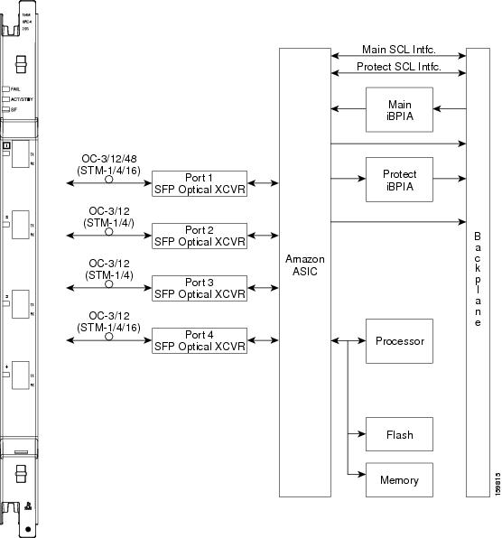
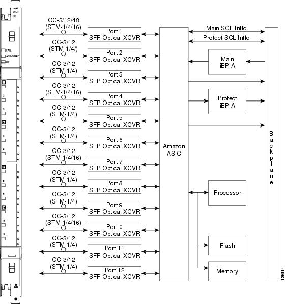
D.3.2 Slot Properties—MRC-12
The slot properties pane displays information about the Cisco ONS 15454 SONET and ONS 15454 SDH slot that is selected in the NE Explorer tree. Use this properties pane to change the card properties.
The MRC-12 multirate card (MRC) provides up to 12 OC-3/STM-1 ports, 12 OC-12/STM-4 ports, or 4 OC-48/STM-16 ports using small form factor pluggables (SFPs), in any combination of line rates. All ports are Telcordia GR-253 compliant. The SFP optics can use SR, IR, LR, coarse wavelength division multiplexing (CWDM), and DWDM SFPs to support unrepeated spans.
The ports operate at up to 2488.32 Mb/s over a single-mode fiber. The MRC-12 card has 12 physical connector adapters with 2 fibers per connector adapter (Tx and Rx). The card supports VT payloads, STS-1 payloads, and concatenated payloads at STS-3c, STS-6c, STS-9c, STS-12c, STS-18c, STS-24c, STS-36c, or STS-48c signal levels. It is fully interoperable with the ONS 15454 G-Series Ethernet cards.
The card supports 1+1 unidirectional and bidirectional facility protection. It also supports 1+1 protection in 4-fiber BLSR applications for the ONS 15454 SONET and in 4-fiber MS-SPRing applications for the ONS 15454 SDH, where both span switching and ring switching might occur. You can provision this card as part of a BLSR, UPSR, or 1+1 linear configuration for the ONS 15454 SONET or an MS-SPRing, SNCP, or linear configuration for the ONS 15454 SDH.
Note Longer distances are possible in an amplified system using dispersion compensation.
Note MRC-12 cards can only protect another MRC-12 card if the card is in the same speed slot (drop or trunk slot) and if both ports have matching line rates. For example, port 1 of the MRC-12 card 1 will protect port 1 of the MRC-12 card 2 only if both ports are provisioned with the same rate (for example, OC-12/STM-4). If the ports are provisioned with different rates, you cannot set a 1+1 protection.
You can install MRC-12 cards in slots 1 to 6 and slots 12 to 17 with an XCVT, XC10G, XC-VXL-2.5G, XC-VXL-10G, or XC-VXC-10G card.
Note The MRC-12 card supports an errorless software-initiated cross-connect card switch when used in a shelf equipped with XC-VXL-2.5G, XC-VXL-10G, or XC-VXC-10G cards.
The maximum bandwidth of the MRC-12 card is determined by the cross-connect card, as shown in the following table.
Table D-49 Maximum Bandwidth by Shelf Slot for the MRC-12 in Different Cross-Connect Configurations
XC Card Type
|
Maximum Bandwidth in the Drop Slot 1 (Slots 1 to 4 and Slots 14 to 17)
|
Maximum Bandwidth in the Trunk Slot 2 (Slots 5, 6, 12, or 13)
|
XCVT
|
OC-12
|
OC-48
|
XC10G/XC-VXC-10G
|
OC-48
|
OC-192
|
XC-VXL-2.5G
|
STM-16
|
STM-16
|
XC-VXC-10G/XC-VXL-10G
|
STM-16
|
STM-64
|
The twelve ports of the MRC-12 card are divided into four groups, with each group having a master port as shown in the following table.
Table D-50 Port Grouping
Group
|
Ports Included
|
Master Port
|
1
|
1
|
1
|
2
|
2, 3, 4
|
4
|
3
|
5, 6, 7, 8
|
7
|
4
|
9, 10, 11, 12
|
10
|
Following are the general port rate configuration rules:
•The maximum bandwidth for each port is OC-48.
•Port 1 can occupy all possible backplane bandwidth but cannot exceed OC-48.
•Each port group can have a maximum of 25% backplane bandwidth, except for group 1.
•Only a master port can occupy all possible bandwidth assigned to the group.
Based on the cross-connect card and slot limitations shown in Table D-49, the following rules apply for various synchronous transport signal (STS) available bandwidths:
•STS-12
–Port 1 is the only port that is usable as an OC-12/STM-4. If port 1 is used as an OC-12/STM-4, all other ports are disabled.
–Ports 1, 4, 7, and 10 are the only ports usable as OC-3/STM-1. If any of these ports is used as an OC-3/STM-1, Ports 2, 3, 5, 6, 8, 9, 11, and 12 are disabled.
•STS-48
–Port 1 is the only port usable as an OC-48/STM-16. If port 1 is used as an OC-48/STM-16, all other ports are disabled.
–Ports 1, 4, 7, and 10 are the only ports usable as OC-12/STM-4.
–If port 4 is used as an OC-12/STM-4, Ports 2 and 3 are disabled.
–If port 7 is used as an OC-12/STM-4, Ports 5, 6, and 8 are disabled.
–If port 10 is used as an OC-12/STM-4, Ports 9, 11, and 12 are disabled.
–Any port can be used as an OC-3/STM-1 as long as all of the above rules are followed.
•STS-192
–Ports 1, 4, 7, and 10 are the only ports usable as OC-48/STM-16.
–If port 4 is used as an OC-48/STM-16, Ports 2 and 3 are disabled.
–If port 7 is used as an OC-48/STM-16, Ports 5, 6, and 8 are disabled.
–If port 10 is used as an OC-48/STM-16, Ports 9, 11, and 12 are disabled.
–If port 4 is used as an OC-12/STM-4, Ports 2 and 3 can be used as an OC-12/STM-4 or OC-3/STM-1.
–If port 7 is used as an OC-12/STM-4, Ports 5, 6, and 8 can be used as an OC-12/STM-4 or OC-3/STM-1.
–If Port 10 is as used as an OC-12/STM-4, Ports 9, 11, and 12 can be used as an OC-12/STM-4 or OC-3/STM-1.
–If port 4 is used as an OC-3/STM-1, Ports 2 and 3 can be used as an OC-12/STM-4 or OC-3/STM-1.
–If port 7 is used as an OC-3/STM-1, Ports 5, 6, and 8 can be used as an OC-12/STM-4 or OC-3/STM-1.
–If port 10 is used as an OC-3/STM-1, Ports 9, 11, and 12 can be used as an OC-12/STM-4 or OC-3/STM-1.
–Any port can be used as an OC-12/STM-4 or OC-3/STM-1, as long as all of the above rules are followed.
For the MRC-12 card, the slot properties pane displays the following tabs: Module View, Identification, Pluggable Provisioning, Line, STS, VC-4 (available only on the ONS 15454 SDH), Loopback, Protection, Alarm Behavior, Transceiver, Auto Laser Shutdown, Section Trace, J1 Path Trace, and Info. The tabs shown depend on the NE configuration.
D.3.2.1 Module View
The Module View Properties pane displays a graphic of the card that is installed in the slot. The number of critical, major, minor, and warning alarms for the card is displayed under Alarm Status. (Moving the mouse pointer over the graphic also displays the alarm counts.) Right-clicking the graphic opens a shortcut menu that you can use to reset, delete, or change the card.
D.3.2.2 Identification
The Identification Properties pane allows you to view and update MRC-12 card identification information.
Table D-51 Field Descriptions for the Identification Properties Pane
Field
|
Description
|
Equipment Type
|
Displays the equipment type that the slot is provisioned for.
|
Actual Equipment Type
|
Displays the actual card that is installed in the slot.
|
Hardware Part Number
|
Displays the card part number that is printed on the top of the card.
|
Hardware Revision
|
Displays the hardware revision number.
|
Serial Number
|
Displays the card serial number that is unique to each card.
|
CLEI Code
|
Displays the CLEI code.
|
Firmware Version
|
Displays the revision number of the software used by the ASIC chip installed on the card.
|
Product ID
|
Displays a product ID string of 63 characters maximum. If the card does not support the product ID, the field shows N/A.
|
Version ID
|
Displays a version ID string in the format "V99_." The version ID always begins with a V and ends with a space. If the card does not support the version ID, the field shows N/A.
|
Admin State
|
The port administration state. It can be:
•IS—In Service.
•IS, AINS—Automatic In Service.
•OOS, DSBLD—Out of Service, Disabled.
•OOS, MT—Out of Service, Maintenance.
|
Service State
|
An autonomously generated state that gives the overall condition of the entity. Service states appear in the format Administrative_State-Operational_State, Status_Attribute.
|
Equipment State
|
Displays the equipment state of the card.
|
Alarm Profile
|
Sets the alarm profile for the card. Check the Suppress Alarms check box to suppress all alarms for this card and its port(s).
|
D.3.2.3 Pluggable Provisioning
The Pluggable Provisioning Properties pane allows you to view and provision pluggable entities; for example, pluggable port module (PPM) and the ports inside these entities.
Table D-52 Field Descriptions for the Pluggable Provisioning Properties Pane
Field
|
Description
|
Pluggable Port Modules
|
Pluggable Number
|
Displays the identifier of the plugin module.
|
Actual Equipment Type
|
Displays the actual pluggable I/O module that is installed in the pluggable slot.
|
Equipment State
|
Displays the equipment state of the card.
|
Admin State
|
The port administration state. It can be:
•IS—In Service.
•IS, AINS—Automatic In Service.
•OOS, DSBLD—Out of Service, Disabled.
•OOS, MT—Out of Service, Maintenance.
|
Service State
|
An autonomously generated state that gives the overall condition of the entity. Service states appear in the format Administrative_State-Operational_State, Status_Attribute.
|
Pluggable Ports
|
Pluggable Number
|
Displays the identifier of the plugin module.
|
Rate
|
Displays the rate of the port inside the pluggable entity.
|
D.3.2.3.1 Provision Pluggable Dialog Box
Click the Create button to launch the Provision Pluggable dialog box. The Provision Pluggable dialog box allows you to provision pluggable entities—for example, the PPM and PIM—and to create the ports inside these entities. See Provision Pluggable Dialog Box for more information.
D.3.2.3.2 Create Port Dialog Box
Use the Create Port dialog box to configure the port rate for a particular pluggable port module (PPM). In the Port Rate field, use the drop-down list to select the new port rate and click OK.
D.3.2.4 Line (ONS 15454 SONET)
The Line Properties pane allows you to view and update optical line performance monitoring information. The Line Properties pane contains the following tabs:
•Line Config Tab
•Line Thresh 15 Min Tab
•Line Thresh 1 Day Tab
•Physical Thresh 15 Min Tab
•Physical Thresh 1 Day Tab
•Section Thresh 15 Min Tab
•Section Thresh 1 Day Tab
•Alarm Thresholds Tab
D.3.2.4.1 Line Config Tab
The Line Config tab allows you to view and change the line settings of the MRC-12 card.
Table D-53 Field Descriptions for the Line Config Tab
Field
|
Description
|
Port Number
|
Displays the port number.
|
Port Name
|
Allows you to add a name for the optical port.
|
Administration State
|
The port administration state. It can be:
•IS—In Service.
•IS, AINS—Automatic In Service.
•OOS, DSBLD—Out of Service, Disabled.
•OOS, MT—Out of Service, Maintenance.
|
Port Rate
|
Sets the rate of the new port.
|
Service State
|
An autonomously generated state that gives the overall condition of the entity. Service states appear in the format Administrative_State-Operational_State, Status_Attribute.
|
SF BER
|
Sets the signal fail bit error rate.
|
SD BER
|
Sets the signal degrade bit error rate.
|
Provide Sync
|
When checked, the card is provisioned as an NE timing reference.
|
EnableSyncMsg
|
When checked, enables synchronization status messages, which allow the node to choose the best timing source.
|
Send Do Not Use
|
When checked, sends a do not use (DUS) message on the S1 byte.
|
BLSR Ext. Byte
|
Select an alternate BLSR byte.
|
Type
|
Defines the port.
|
AINS Soak (H:M)
|
Automatic in-service soak. The duration remaining before the traffic/termination transitions to IS state.
|
AINS Soak Count Down (H:M)
|
Automatic in-service soak countdown. Displays the remaining time of valid input signal in hh:mm format, after which the card becomes in service (IS) automatically.
|
Admin SSM
|
If the node does not receive an SSM signal, it defaults to STU (synchronization traceability unknown). Admin SSM allows you to override the STU value with one of the following:
•PRS—Primary reference source (Stratum 1)
•STS2—Stratum 2
•TNC—Transit node clock
•STS3E—Stratum 3E
•STS3—Stratum 3
•SMC—SONET minimum clock
•ST4—Stratum 4
|
Send <FF> DoNotUse
|
When checked, sends a special do not use (DUS) (0xff) message on the S1 byte.
|
PJSTSMon#
|
Sets the STS that will be used for pointer justification. If set to 0, no STS is monitored. Only one STS can be monitored on each OC-N port.
•0 (default) - 3 (OC3, per port)
•0 (default) - 12 (OC-12)
|
Reach
|
Allows you to provision the reach value. You can choose Auto Provision, which allows the system to automatically provision the reach from the PPM reach value on the hardware. Choose one of the following reach distances:
Note The reach distances options that appear in the drop-down list depend on the card selected.
•SR (short reach, up to 2 km distance)
•SR 1 (up to 2 km distance)
•IR 1 (intermediate reach, up to 15 km distance)
•IR 2 (up to 40 km distance)
•LR 1 (long reach, up to 40 km distance)
•LR 2 (up to 80 km distance)
•LR 3 (up to 80 km distance)
•I1
•S1
•S2
•L1
•L2
•L3
•SX (up to 550 m or 270 m distance based on 50 um/62.5 um diameter fiber)
•LX (up to 10 km or 550 m distance based on 50 um/62.5 um diameter fiber)
•CX
•T
•DX (up to 40 km distance)
•HX (up to 40 km distance)
•ZX (up to 80 km distance)
•VX (up to 100 km distance)
|
Wavelength
|
Allows you to provision the wavelength frequency.
|
D.3.2.4.2 Line Thresh 15 Min Tab
The Line Thresh 15 Min tab allows you to view and change the 15-minute near- and far-end line thresholds of the MRC-12 card.
Table D-54 Field Descriptions for the Line Thresh 15 Min Tab
Field
|
Description
|
Near End
|
Port Number
|
Displays the optical port number.
|
ES-L
|
Displays the errored seconds-line.
|
SES-L
|
Displays the severely errored seconds-line.
|
CV-L
|
Displays the coding violations-line.
|
UAS-L
|
Displays the unavailable seconds-line.
|
FC-L
|
Displays the failure count-line.
|
PSC
|
Protection switching count-line.
|
PSD
|
Protection switching duration-line.
|
PSC-W
|
Protection switching count-working.
|
PSD-W
|
Protection switching duration-working.
|
PSC-S
|
Protection switching count-span.
|
PSD-S
|
Protection switching duration-span.
|
PSC-R
|
Protection switching count-ring.
|
PSD-R
|
Protection switching duration-ring.
|
Far End
|
Port Number
|
Displays the optical port number.
|
ES-L
|
Displays the errored seconds-line.
|
SES-L
|
Displays the severely errored seconds-line.
|
CV-L
|
Displays the coding violations-line.
|
UAS-L
|
Displays the unavailable seconds-line.
|
FC-L
|
Displays the failure count-line.
|
D.3.2.4.3 Line Thresh 1 Day Tab
The Line Thresh 1 Day tab allows you to view and change the 1-day near- and far-end line thresholds of the MRC-12 card.
Table D-55 Field Descriptions for the Line Thresh 1 Day Tab
Field
|
Description
|
Near End
|
Port Number
|
Displays the optical port number.
|
ES-L
|
Displays the errored seconds-line.
|
SES-L
|
Displays the severely errored seconds-line.
|
CV-L
|
Displays the coding violations-line.
|
UAS-L
|
Displays the unavailable seconds-line.
|
FC-L
|
Displays the failure count-line.
|
PSC
|
Protection switching count-line.
|
PSD
|
Protection switching duration-line.
|
PSC-W
|
Protection switching count-working.
|
PSD-W
|
Protection switching duration-working.
|
PSC-S
|
Protection switching count-span.
|
PSD-S
|
Protection switching duration-span.
|
PSC-R
|
Protection switching count-ring.
|
PSD-R
|
Protection switching duration-ring.
|
Far End
|
Port Number
|
Displays the optical port number.
|
ES-L
|
Displays the errored seconds-line.
|
SES-L
|
Displays the severely errored seconds-line.
|
CV-L
|
Displays the coding violations-line.
|
UAS-L
|
Displays the unavailable seconds-line.
|
FC-L
|
Displays the failure count-line.
|
D.3.2.4.4 Physical Thresh 15 Min Tab
The Physical Thresh 15 Min tab allows you to view and change the 15-minute near-end physical thresholds of the MRC-12 card.
Table D-56 Field Descriptions for the Physical Thresh 15 Min Tab
Field
|
Description
|
Near End
|
Port Number
|
Displays the port number.
|
LBC-HIGH
|
Maximum laser bias current. The default is (15 min): 150 percent.
|
LBC-LOW
|
Minimum laser bias current. The default is (15 min): 50 percent.
|
OPT-HIGH
|
Maximum optical power transmitted. The default is (15 min): 120 percent.
|
OPT-LOW
|
Minimum optical power transmitted. The default is (15 min): 80 percent.
|
OPR-HIGH
|
Maximum optical power received. The default is (15 min): 200 percent.
|
OPR-LOW
|
Minimum optical power received. The default is (15 min): 50 percent.
|
Set OPR
|
Setting the optical power received (OPR) establishes the received power level as 100 percent. If the receiver power decreases, then the OPR percentage decreases to reflect the loss in receiver power. For example, if the receiver power decreases 3 dBm, the OPR decreases 50 percent.
|
D.3.2.4.5 Physical Thresh 1 Day Tab
The Physical Thresh 1 Day tab allows you to view and change the 1-day near-end physical thresholds of the MRC-12 card.
Table D-57 Field Descriptions for the Physical Thresh 1 Day Tab
Field
|
Description
|
Near End
|
Port Number
|
Displays the port number.
|
LBC-HIGH
|
Maximum laser bias current. The default is (15 min): 150 percent.
|
LBC-LOW
|
Minimum laser bias current. The default is (15 min): 50 percent.
|
OPT-HIGH
|
Maximum optical power transmitted. The default is (15 min): 120 percent.
|
OPT-LOW
|
Minimum optical power transmitted. The default is (15 min): 80 percent
|
OPR-HIGH
|
Maximum optical power received. The default is (15 min): 200 percent.
|
OPR-LOW
|
Minimum optical power received. The default is (15 min): 50 percent.
|
Set OPR
|
Setting the OPR establishes the received power level as 100 percent. If the receiver power decreases, then the OPR percentage decreases to reflect the loss in receiver power. For example, if the receiver power decreases 3 dBm, the OPR decreases 50 percent.
|
D.3.2.4.6 Section Thresh 15 Min Tab
The Section Thresh 15 Min tab allows you to view and change the 15-minute near-end section thresholds of the MRC-12 card.
Table D-58 Field Descriptions for the Section Thresh 15 Min Tab
Field
|
Description
|
Near End
|
Port Number
|
Displays the port number.
|
CV-S
|
Displays the coding violations-section.
|
ES-S
|
Displays the errored seconds-section.
|
SES-S
|
Displays the severely errored seconds-section.
|
SEFS-S
|
Displays the severely errored framing seconds-section.
|
D.3.2.4.7 Section Thresh 1 Day Tab
The Section Thresh 1 Day tab allows you to view and change the 1-day near-end section thresholds of the MRC-12 card.
Table D-59 Field Descriptions for the Section Thresh 1 Day Tab
Field
|
Description
|
Near End
|
Port Number
|
Displays the port number.
|
CV-S
|
Displays the coding violations-section.
|
ES-S
|
Displays the errored seconds-section.
|
SES-S
|
Displays the severely errored seconds-section.
|
SEFS-S
|
Displays the severely errored framing seconds-section.
|
D.3.2.4.8 Alarm Thresholds Tab
The Alarm Thresholds tab allows you to select the thresholds for the alarms.
Table D-60 Field Descriptions for the Alarm Thresholds Tab
Field
|
Description
|
Port No.
|
Port number.
|
LBC-HIGH
|
Maximum laser bias current.
|
LBC-LOW
|
Minimum laser bias current.
|
OPT-HIGH
|
Maximum optical power transmitted.
|
OPT-LOW
|
Minimum optical power transmitted.
|
OPR-HIGH
|
Maximum optical power received.
|
OPR-LOW
|
Minimum optical power received.
|
Set OPR
|
Setting the OPR establishes the received power level as 100 percent. If the receiver power decreases, then the OPR percentage decreases to reflect the loss in receiver power. For example, if the receiver power decreases 3 dBm, the OPR decreases 50 percent.
|
D.3.2.5 Line (ONS 15454 SDH)
The Line Properties pane allows you to view and update optical line performance monitoring information. The Line Properties pane contains the following tabs:
•Line Config Tab
•MS Thresh 15 Min Tab
•MS Thresh 1 Day Tab
•Physical Thresh 15 Min Tab
•Physical Thresh 1 Day Tab
•RS Thresh 15 Min
•RS Thresh 1 Day Tab
•Alarm Thresholds Tab
D.3.2.5.1 Line Config Tab
The Line Config tab allows you to view and change the line settings of the MRC-12 card.
Table D-61 Field Descriptions for the Line Config Tab
Field
|
Description
|
Port Number
|
Displays the port number.
|
Port Name
|
Allows you to add a name for the optical port.
|
Admin State
|
The port administration state. It can be:
•IS—In Service.
•IS, AINS—Automatic In Service.
•OOS, DSBLD—Out of Service, Disabled.
•OOS, MT—Out of Service, Maintenance.
|
Port Rate
|
Sets the rate of the new port.
|
Service State
|
An autonomously generated state that gives the overall condition of the entity. Service states appear in the format Administrative_State-Operational_State, Status_Attribute.
|
SF BER
|
Sets the signal fail bit error rate.
|
SD BER
|
Sets the signal degrade bit error rate.
|
Provide Sync
|
When checked, the card is provisioned as an NE timing reference.
|
EnableSyncMsg
|
When checked, enables synchronization status messages, which allow the node to choose the best timing source.
|
Send Do Not Use
|
When checked, sends a do not use (DUS) message on the S1 byte.
|
MS-SPRing Ext. Byte
|
Select an alternate MS-SPRing byte.
|
Type
|
Defines the port.
|
AINS Soak (H:M)
|
Automatic in-service soak. The duration remaining before the traffic/termination transitions to IS state.
|
AINS Soak Count Down (H:M)
|
Automatic in-service soak countdown. Displays the remaining time of valid input signal in hh:mm format, after which the card becomes in service (IS) automatically.
|
Admin SSM
|
If the node does not receive an SSM signal, it defaults to STU (synchronization traceability unknown). Admin SSM allows you to override the STU value with one of the following:
•PRS—Primary reference source (Stratum 1)
•STS2—Stratum 2
•TNC—Transit node clock
•STS3E—Stratum 3E
•STS3—Stratum 3
•SMC—SONET minimum clock
•ST4—Stratum 4
|
Send <FF> DoNotUse
|
When checked, sends a special do not use (DUS) (0xff) message on the S1 byte.
|
PJ VC-4 Mon#
|
Sets the VC that will be used for pointer justification. If set to 0, no VC is monitored. Only one VC can be monitored on each STM port.
|
Reach
|
Allows you to provision the reach value. You can choose Auto Provision, which allows the system to automatically provision the reach from the PPM reach value on the hardware. Choose one of the following reach distances:
Note The reach distances options that appear in the drop-down list depend on the card selected.
•SR (short reach, up to 2 km distance)
•SR 1 (up to 2 km distance)
•IR 1 (intermediate reach, up to 15 km distance)
•IR 2 (up to 40 km distance)
•LR 1 (long reach, up to 40 km distance)
•LR 2 (up to 80 km distance)
•LR 3 (up to 80 km distance)
•I1
•S1
•S2
•L1
•L2
•L3
•SX (up to 550 m or 270 m distance based on 50 um/62.5 um diameter fiber)
•LX (up to 10 km or 550 m distance based on 50 um/62.5 um diameter fiber)
•CX
•T
•DX (up to 40 km distance)
•HX (up to 40 km distance)
•ZX (up to 80 km distance)
•VX (up to 100 km distance)
|
Wavelength
|
Allows you to provision the wavelength frequency.
|
D.3.2.5.2 MS Thresh 15 Min Tab
The MS Thresh 15 Min tab allows you to view and change the 15-minute near- and far-end line thresholds of the MRC-12 card.
Table D-62 Field Descriptions for the MS Thresh 15 Min Tab
Field
|
Description
|
Near End
|
Port Number
|
Displays the optical port number.
|
EB-MS
|
Displays the errored block-multiplex section.
|
BBE-MS
|
Displays the background block errors-multiplex section.
|
ES-MS
|
Displays the errored seconds-multiplex section.
|
SES-MS
|
Displays the severely errored seconds-multiplex section.
|
UAS-MS
|
Displays the unavailable seconds-multiplex section.
|
PSC
|
Displays the protection switching count.
|
PSD
|
Displays the protection switching duration.
|
PSC-W
|
Displays the protection switching count-working.
|
PSD-W
|
Displays the protection switching duration-working.
|
PSC-S
|
Displays the protection switching count-span.
|
PSD-S
|
Displays the protection switching duration-span.
|
PSC-R
|
Displays the protection switching count-ring.
|
PSD-R
|
Displays the protection switching duration-ring.
|
Far End
|
Port Number
|
Displays the optical port number.
|
EB-MS
|
Displays the errored block-multiplex section.
|
BBE-MS
|
Displays the background block errors-multiplex section.
|
ES-MS
|
Displays the errored seconds-multiplex section.
|
SES-MS
|
Displays the severely errored seconds-multiplex section.
|
UAS-MS
|
Displays the unavailable seconds-multiplex section.
|
D.3.2.5.3 MS Thresh 1 Day Tab
The MS Thresh 1 Day tab allows you to view and change the 1-day near- and far-end line thresholds of the MRC-12 card.
Table D-63 Field Descriptions for the MS Thresh 1 Day Tab
Field
|
Description
|
Near End
|
Port Number
|
Displays the optical port number.
|
EB-MS
|
Displays the errored block-multiplex section.
|
BBE-MS
|
Displays the background block errors-multiplex section.
|
ES-MS
|
Displays the errored seconds-multiplex section.
|
SES-MS
|
Displays the severely errored seconds-multiplex section.
|
UAS-MS
|
Displays the unavailable seconds-multiplex section.
|
PSC
|
Displays the protection switching count.
|
PSD
|
Displays the protection switching duration.
|
PSC-W
|
Displays the protection switching count-working.
|
PSD-W
|
Displays the protection switching duration-working.
|
PSC-S
|
Displays the protection switching count-span.
|
PSD-S
|
Displays the protection switching duration-span.
|
PSC-R
|
Displays the protection switching count-ring.
|
PSD-R
|
Displays the protection switching duration-ring.
|
Far End
|
Port Number
|
Displays the optical port number.
|
EB-MS
|
Displays the errored block-multiplex section.
|
BBE-MS
|
Displays the background block errors-multiplex section.
|
ES-MS
|
Displays the errored seconds-multiplex section.
|
SES-MS
|
Displays the severely errored seconds-multiplex section.
|
UAS-MS
|
Displays the unavailable seconds-multiplex section.
|
D.3.2.5.4 Physical Thresh 15 Min Tab
The Physical Thresh 15 Min tab allows you to view and change the 15-minute near-end physical thresholds of the MRC-12 card.
Table D-64 Field Descriptions for the Physical Thresh 15 Min Tab
Field
|
Description
|
Near End
|
Port Number
|
Displays the port number.
|
LBC-HIGH
|
Maximum laser bias current. The default is (15 min): 150 percent.
|
LBC-LOW
|
Minimum laser bias current. The default is (15 min): 50 percent.
|
OPT-HIGH
|
Maximum optical power transmitted. The default is (15 min): 120 percent.
|
OPT-LOW
|
Minimum optical power transmitted. The default is (15 min): 80 percent.
|
OPR-HIGH
|
Maximum optical power received. The default is (15 min): 200 percent.
|
OPR-LOW
|
Minimum optical power received. The default is (15 min): 50 percent.
|
Set OPR
|
Setting the OPR establishes the received power level as 100 percent. If the receiver power decreases, then the OPR percentage decreases to reflect the loss in receiver power. For example, if the receiver power decreases 3 dBm, the OPR decreases 50 percent.
|
D.3.2.5.5 Physical Thresh 1 Day Tab
The Physical Thresh 1 Day tab allows you to view and change the 1-day near-end physical thresholds of the MRC-12 card.
Table D-65 Field Descriptions for the Physical Thresh 1 Day Tab
Field
|
Description
|
Near End
|
Port Number
|
Displays the port number.
|
LBC-HIGH
|
Maximum laser bias current. The default is (15 min): 150 percent.
|
LBC-LOW
|
Minimum laser bias current. The default is (15 min): 50 percent.
|
OPT-HIGH
|
Maximum optical power transmitted. The default is (15 min): 120 percent.
|
OPT-LOW
|
Minimum optical power transmitted. The default is (15 min): 80 percent
|
OPR-HIGH
|
Maximum optical power received. The default is (15 min): 200 percent.
|
OPR-LOW
|
Minimum optical power received. The default is (15 min): 50 percent.
|
Set OPR
|
Setting the OPR establishes the received power level as 100 percent. If the receiver power decreases, then the OPR percentage decreases to reflect the loss in receiver power. For example, if the receiver power decreases 3 dBm, the OPR decreases 50 percent.
|
D.3.2.5.6 RS Thresh 15 Min
The RS Thresh 15 Min tab allows you to view and change the 15-minute near-end section thresholds of the MRC-12 card.
Table D-66 Field Descriptions for the RS Thresh 15 Min Tab
Field
|
Description
|
Near End
|
Port Number
|
Displays the optical port number.
|
EB-RS
|
Displays the errored block-regenerator section.
|
BBE-RS
|
Displays the background block errors-regenerator section.
|
ES-RS
|
Displays the errored seconds-regenerator section.
|
SES-RS
|
Displays the severely errored seconds-regenerator section.
|
UAS-RS
|
Displays the unavailable seconds-regenerator section.
|
OFS-RS
|
Displays the out of framing seconds-regenerator section.
|
D.3.2.5.7 RS Thresh 1 Day Tab
The RS Thresh 1 Day tab allows you to view and change the 1-day near-end section thresholds of the MRC-12 card.
Table D-67 Field Descriptions for the RS Thresh 1 Day Tab
Field
|
Description
|
Near End
|
Port Number
|
Displays the optical port number.
|
EB-RS
|
Displays the errored block-regenerator section.
|
BBE-RS
|
Displays the background block errors-regenerator section.
|
ES-RS
|
Displays the errored seconds-regenerator section.
|
SES-RS
|
Displays the severely errored seconds-regenerator section.
|
UAS-RS
|
Displays the unavailable seconds-regenerator section.
|
OFS-RS
|
Displays the out of framing seconds-regenerator section.
|
D.3.2.5.8 Alarm Thresholds Tab
The Alarm Thresholds tab allows you to select the thresholds for the alarms.
Table D-68 Field Descriptions for the Alarm Thresholds Tab
Field
|
Description
|
Port No.
|
Port number.
|
LBC-HIGH
|
Maximum laser bias current.
|
LBC-LOW
|
Minimum laser bias current.
|
OPT-HIGH
|
Maximum optical power transmitted.
|
OPT-LOW
|
Minimum optical power transmitted.
|
OPR-HIGH
|
Maximum optical power received.
|
OPR-LOW
|
Minimum optical power received.
|
Set OPR
|
Setting the OPR establishes the received power level as 100 percent. If the receiver power decreases, then the OPR percentage decreases to reflect the loss in receiver power. For example, if the receiver power decreases 3 dBm, the OPR decreases 50 percent.
|
D.3.2.6 STS (ONS 15454 SONET)
The STS Properties pane allows you to view and update MRC-12 STS information. The STS Properties pane contains the following tabs:
•STS Config Tab
•Path Thresh 15 Min Tab
•Path Thresh 1 Day Tab
•Customer Info Tab
D.3.2.6.1 STS Config Tab
The STS Config tab allows you to view and change the STS settings of the MRC-12 card.
Table D-69 Field Descriptions for the STS Config Tab
Field
|
Description
|
STS Number
|
Displays the synchronous transport signal number information.
|
IPPM Enabled
|
Check to enable IPPM and uncheck to disable IPPM.
|
XC Loopback
|
Displays the cross-connect loopback status.
|
D.3.2.6.2 Path Thresh 15 Min Tab
The Path Thresh 15 Min tab allows you to view and change the 15-minute path thresholds of the MRC-12 card.
Table D-70 Field Descriptions for the Path Thresh 15 Min Tab
Field
|
Description
|
Near End
|
STS Number
|
Displays the synchronous transport signal number information.
|
CV-P
|
Displays coding violations-path information.
|
ES-P
|
Displays errored seconds-path information.
|
SES-P
|
Displays severely errored seconds-path information.
|
UAS-P
|
Displays unavailable seconds-path information.
|
FC-P
|
Displays failure count-path information.
|
PPJC-Pdet
|
Displays positive pointer justification count, STS path detected.
|
NPJC-Pdet
|
Displays negative pointer justification count, STS path detected.
|
PPJC-Pgen
|
Displays positive pointer justification count, STS path generated.
|
NPJC-Pgen
|
Displays negative pointer justification count, STS path generated.
|
PJCS-Pdet
|
Displays positive pointer justification count, STS path detected.
|
PJCS-Pgen
|
Displays positive pointer justification count, STS path generated.
|
PJC-Diff
|
Displays the sum of the absolute values of differences between positive transmitted and received, and negative transmitted and received. The important metric on pointer justification is not the exact counts, but how many were absorbed.
|
Far End
|
STS No.
|
Displays the synchronous transport signal number information.
|
CV-P
|
Displays coding violations-path information.
|
ES-P
|
Displays errored seconds-path information.
|
SES-P
|
Displays severely errored seconds-path information.
|
UAS-P
|
Displays unavailable seconds-path information.
|
FC-P
|
Displays failure count-path information.
|
D.3.2.6.3 Path Thresh 1 Day Tab
The Path Thresh 1 Day tab allows you to view and change the 1-day path thresholds of the MRC-12 card.
Table D-71 Field Descriptions for the Path Thresh 1 Day Tab
Field
|
Description
|
Near End
|
STS Number
|
Displays the synchronous transport signal number information.
|
CV-P
|
Displays coding violations-path information.
|
ES-P
|
Displays errored seconds-path information.
|
SES-P
|
Displays severely errored seconds-path information.
|
UAS-P
|
Displays unavailable seconds-path information.
|
FC-P
|
Displays failure count-path information.
|
PPJC-Pdet
|
Displays positive pointer justification count, STS path detected.
|
NPJC-Pdet
|
Displays negative pointer justification count, STS path detected.
|
PPJC-Pgen
|
Displays positive pointer justification count, STS path generated.
|
NPJC-Pgen
|
Displays negative pointer justification count, STS path generated.
|
PJCS-Pdet
|
Displays positive pointer justification count, STS path detected.
|
PJCS-Pgen
|
Displays positive pointer justification count, STS path generated.
|
PJC-Diff
|
Displays the sum of the absolute values of differences between positive transmitted and received, and negative transmitted and received. The important metric on pointer justification is not the exact counts, but how many were absorbed.
|
Far End
|
STS No.
|
Displays the synchronous transport signal number information.
|
CV-P
|
Displays coding violations-path information.
|
ES-P
|
Displays errored seconds-path information.
|
SES-P
|
Displays severely errored seconds-path information.
|
UAS-P
|
Displays unavailable seconds-path information.
|
FC-P
|
Displays failure count-path information.
|
D.3.2.6.4 Customer Info Tab
The Customer Info tab allows you to view the customer information.
Table D-72 Field Descriptions for the Customer Info Tab
Field
|
Description
|
STS No.
|
The STS number.
|
Customer ID
|
The user-defined customer ID number.
|
Service ID
|
The user-defined service ID number.
|
D.3.2.7 VC-4 (ONS 15454 SDH)
The VC-4 Properties pane allows you to view and update MRC-12 VC-4 information. The VC-4 Properties pane contains the following tabs:
•VC-4 Config Tab
•SDH Path Thresh 15 Min Tab
•SDH Path Thresh 1 Day Tab
•Customer Info Tab
D.3.2.7.1 VC-4 Config Tab
The VC-4 Config tab allows you to view and change the VC-4 settings of the MRC-12 card.
Table D-73 Field Descriptions for the VC-4 Config Tab
Field
|
Description
|
VC Number
|
Displays the VC number.
|
IPPM Enabled
|
Check to enable intermediate path performance monitoring (IPPM) and uncheck to disable IPPM.
|
XC Loopback
|
Indicates cross-connect loopback.
|
D.3.2.7.2 SDH Path Thresh 15 Min Tab
The SDH Path Thresh 15 Min tab allows you to view and change the 15-minute path thresholds of the MRC-12 card.
Table D-74 Field Descriptions for the SDH Path Thresh 15 Min Tab
Field
|
Description
|
Near End
|
VC Number
|
Displays the VC-4 port number.
|
EB-HP
|
Errored block-higher-order path.
|
ES-HP
|
Errored seconds-higher-order path.
|
SES-HP
|
Severely errored seconds-higher-order path.
|
UAS-HP
|
Unavailable seconds-higher-order path.
|
BBE-HP
|
Background block errors-higher-order path.
|
PPJC-Pdet
|
Positive pointer justification count, path detected (PPJC-Pdet) is a count of the positive pointer justifications detected on a particular path on an incoming SDH signal.
|
NPJC-Pdet
|
Negative pointer justification count, path detected (NPJC-Pdet) is a count of the negative pointer justifications detected on a particular path on an incoming SDH signal.
|
PPJC-Pgen
|
Positive pointer justification count, path generated (PPJC-Pgen) is a count of the positive pointer justifications generated for a particular path.
|
NPJC-Pgen
|
Negative pointer justification count, path generated (MS-NPJC-Pgen) is a count of the negative pointer justifications generated for a particular path.
|
PJCS-Pdet
|
Number of higher-order path pointer justification count seconds detected on a particular path.
|
PJCS-Pgen
|
Number of higher-order path pointer justification count seconds generated for a particular path.
|
PJC-Diff
|
Displays the sum of the absolute values of differences between positive transmitted and received, and negative transmitted and received. The important metric on pointer justification is not the exact counts, but how many were absorbed.
|
Far End
|
VC Number
|
Displays the VC-4 port number.
|
EB-HP
|
Errored block-higher-order path.
|
ES-HP
|
Errored seconds-higher-order path.
|
SES-HP
|
Severely errored seconds-higher-order path.
|
UAS-HP
|
Unavailable seconds-higher-order path.
|
BBE-HP
|
Background block errors-higher-order path.
|
D.3.2.7.3 SDH Path Thresh 1 Day Tab
The SDH Path Thresh 1 Day tab allows you to view and change the 1-day path thresholds of the MRC-12 card.
Table D-75 Field Descriptions for the SDH Path Thresh 1 Day Tab
Field
|
Description
|
Near End
|
VC Number
|
Displays the VC-4 port number.
|
EB-HP
|
Errored block-higher-order path.
|
ES-HP
|
Errored seconds-higher-order path.
|
SES-HP
|
Severely errored seconds-higher-order path.
|
UAS-HP
|
Unavailable seconds-higher-order path.
|
BBE-HP
|
Background block errors-higher-order path.
|
PPJC-Pdet
|
Positive pointer justification count, path detected (PPJC-Pdet) is a count of the positive pointer justifications detected on a particular path on an incoming SDH signal.
|
NPJC-Pdet
|
Negative pointer justification count, path detected (NPJC-Pdet) is a count of the negative pointer justifications detected on a particular path on an incoming SDH signal.
|
PPJC-Pgen
|
Positive pointer justification count, path generated (PPJC-Pgen) is a count of the positive pointer justifications generated for a particular path.
|
NPJC-Pgen
|
Negative pointer justification count, path generated (MS-NPJC-Pgen) is a count of the negative pointer justifications generated for a particular path.
|
PJCS-Pdet
|
Number of higher-order path pointer justification count seconds detected on a particular path.
|
PJCS-Pgen
|
Number of higher-order path pointer justification count seconds generated for a particular path.
|
PJC-Diff
|
Displays the sum of the absolute values of differences between positive transmitted and received, and negative transmitted and received. The important metric on pointer justification is not the exact counts, but how many were absorbed.
|
Far End
|
VC Number
|
Displays the VC-4 port number.
|
EB-HP
|
Errored block-higher-order path.
|
ES-HP
|
Errored seconds-higher-order path.
|
SES-HP
|
Severely errored seconds-higher-order path.
|
UAS-HP
|
Unavailable seconds-higher-order path.
|
BBE-HP
|
Background block errors-higher-order path.
|
D.3.2.7.4 Customer Info Tab
The Customer Info tab allows you to view the customer information.
Table D-76 Field Descriptions for the Customer Info Tab
Field
|
Description
|
VC No.
|
The VC number.
|
Customer ID
|
The user-defined customer ID number.
|
Service ID
|
The user-defined service ID number.
|
D.3.2.8 Loopback
The Loopback Properties pane allows you to view and update loopback information.
Table D-77 Field Descriptions for the Loopback Properties Pane
Field
|
Description
|
Port Number
|
Displays the port number.
|
Administration State
|
The port administration state. It can be:
•IS—In Service.
•IS, AINS—Automatic In Service.
•OOS, DSBLD—Out of Service, Disabled.
•OOS, MT—Out of Service, Maintenance.
|
Loopback Type
|
Allows you to configure a port to terminal loopback (Inward) or Facility (Line), or clear the current loopback (none).
Note The line state must be OOS_MT before you can configure the loopback type.
|
Service State
|
An autonomously generated state that gives the overall condition of the entity. Service states appear in the format Administrative_State-Operational_State, Status_Attribute.
|
Send AIS on Facility Loopback
|
When selected, sends AIS on the facility loopback.
|
Send AIS on Terminal Loopback
|
When selected, sends AIS on the terminal loopback.
|
D.3.2.9 Protection
The Protection Properties pane allows you to view and update MRC-12 protection group information.
Table D-78 Field Descriptions for the Protection Properties Pane
Field
|
Description
|
Protection Groups
|
Displays a list of available protection groups.
|
Protection Group Details
|
Displays details about the selected protection group.
|
D.3.2.10 Alarm Behavior
The Alarm Behavior Properties pane allows you to view and update alarm profile information.
Table D-79 Field Descriptions for the Alarm Behavior Properties Pane
Field
|
Description
|
Port Number
|
Displays the card port number.
|
Alarm Profile
|
Choose an alarm profile for the port from the drop-down list. Values are Default, Inherited, or a customized alarm profile.
|
Suppress Alarms
|
When checked, all alarms are suppressed for the port.
|
Alarm Profile
|
Choose an alarm profile for all ports.
|
Force to All Ports
|
When clicked, forces all the ports to the selected alarm profile.
|
D.3.2.11 Transceiver
The Transceiver Properties pane allows you to view and update MRC-12 transceiver information.
Table D-80 Field Descriptions for the Transceiver Properties Pane
Field
|
Description
|
Port No.
|
PIM number, PPM number, or port number.
|
Non-normalized LBC (mA)
|
The actual operating value of laser bias current (in mA) for the specified card port.
|
Non-normalized OPT (dBm)
|
The actual operating value of optical power transmitted (in dBm) for the specified card port.
|
Non-normalized OPR (dBm)
|
The actual operating value of optical power received (in dBm) for the specified card port.
|
D.3.2.12 Auto Laser Shutdown
The Auto Laser Shutdown Properties pane allows you to view and update MRC-12 ALS parameters.
Table D-81 Field Descriptions for the Auto Laser Shutdown Properties Pane
Field
|
Description
|
Port No.
|
Displays the port number.
|
ALS Mode
|
Displays the ALS mode (Disabled, Auto Restart, Manual Restart, or Manual Restart for Test).
|
Rec. Pulse Dur. (sec)
|
Allows you to set the received laser pulse duration, in seconds. The range is from 2.0 to 100.0 seconds.
|
Rec. Pulse Int. (sec)
|
Allows you to set the received laser pulse interval, in seconds. The range is from 60 to 300 seconds.
|
Status
|
Displays the current laser status. Values are Shutdown or Not Shutdown.
|
Request Restart
|
When selected, allows you to request a laser restart. This parameter is configurable only when the ALS mode is set to Manual Restart or Manual Restart for Test and when the laser status is Shutdown.
|
D.3.2.13 Section Trace
The Section Trace Properties pane allows you to change the section trace settings for the MRC-12 card.
Table D-82 Field Descriptions for the Section Trace Properties Pane
Field
|
Description
|
Port Number
|
Displays the port number.
|
Trace Mode
|
The trace mode (Off/None or Manual).
|
Disable AIS/RDI on TIM-S
|
Allows you to disable the Alarm Indication Signal (AIS) and the Remote Defect Indication (RDI) when the path Trace Identifier Mismatch Section (TIM-S) alarm is detected.
|
Transmit Length
|
Select a transmit length for the trace.
|
Current Transmit String
|
Displays the current transmit string. The trail trace identifier is 64 bytes in length.
|
Current Expected String
|
Displays the current expected string; sets a new expected string.
|
Current Received String
|
Displays the current received string.
|
D.3.2.14 J1 Path Trace
The J1 Path Trace Properties pane allows you to view and update J1 path trace information.
Table D-83 Field Descriptions for the J1 Path Trace Properties Pane
Field
|
Description
|
Port Number
|
Displays the port number.
|
STS | VC-4 Number
|
Displays the STS or VC-4 number.
|
Expected String
|
Displays the current expected string.
|
Received String
|
Displays the current received string.
|
Mode
|
Displays the path trace mode (Off/None, Auto, or Manual).
|
C2
|
Represents a machine-generated J1/J2 payload label byte.
|
D.3.2.15 Info
The Info Properties pane allows you to view nominal operating values set during manufacturing for the MRC-12 card.
Table D-84 Field Descriptions for the Info Properties Pane
Field
|
Description
|
Attribute
|
Displays the nominal card specification.
|
Value
|
Displays the value of the attribute.
|
Note See Table 1-22 for descriptions of actions that you can perform using the buttons at the bottom of the window.
D.3.3 Slot Properties—MRC25G-4
The slot properties pane displays information about the Cisco ONS 15454 SONET slot that is selected in the NE Explorer tree. Use this properties pane to change the card properties.
The MRC-2.5G-4 multirate card provides up to four OC-3/STM-1 ports, four OC-12/STM-4 ports, or one OC-48/STM-16 port using small form factor pluggables (SFPs), in various combinations of line rates. All ports are Telcordia GR-253 compliant. The SFP optics can use SR, IR, LR, coarse wavelength division multiplexing (CWDM), and DWDM SFPs to support unrepeated spans.
The ports operate at up to 2488.320 Mb/s over a single-mode fiber. The MRC-2.5G-4 card has four physical connector adapters with two fibers per connector adapter (Tx and Rx). The card supports VT payloads, STS-1 payloads, and concatenated payloads at STS-3c, STS-6c, STS-9c, STS-12c, STS-18c, STS-24c, STS-36c, or STS-48c signal levels. It is fully interoperable with the ONS 15454 G-Series Ethernet cards.
The MRC-2.5G-4 port contains a transmit and receive connector (labeled) on the card faceplate. The card supports 1+1 unidirectional and bidirectional facility protection. It also supports 1+1 protection in four-fiber BLSR applications where both span switching and ring switching might occur. You can provision this card as part of an BLSR, UPSR, or 1+1 linear configuration.
Note Longer distances are possible in an amplified system using dispersion compensation.
The following figure shows the MRC-2.5G-4 faceplate and block diagram.
Figure D-1 MRC-2.5G-4 Module
For the MRC25G-4 card, the slot properties pane displays the following tabs: Module View, Identification, Pluggable Provisioning, Line, STS, Loopback, Protection, Alarm Behavior, Transceiver, Auto Laser Shutdown, Section Trace, J1 Path Trace, and Info. The tabs shown depend on the NE configuration.
D.3.3.1 Module View
The Module View Properties pane displays a graphic of the card that is installed in the slot. The number of critical, major, minor, and warning alarms for the module is displayed under Alarm Status. (Moving the mouse pointer over the graphic also displays the alarm counts.) Right-clicking the graphic opens a shortcut menu that you can use to reset, delete, or change the card.
D.3.3.2 Identification
The Identification Properties pane allows you to view and update MRC25G-4 card identification information.
Table D-85 Field Descriptions for the Identification Properties Pane
Field
|
Description
|
Equipment Type
|
Displays the equipment type that the slot is provisioned for.
|
Actual Equipment Type
|
Displays the actual card that is installed in the slot.
|
Hardware Part Number
|
Displays the card part number that is printed on the top of the card.
|
Hardware Revision
|
Displays the hardware revision number.
|
Serial Number
|
Displays the card serial number that is unique to each card.
|
CLEI Code
|
Displays the CLEI code.
|
Firmware Version
|
Displays the revision number of the software used by the ASIC chip installed on the card.
|
Product ID
|
Displays a product ID string of 63 characters maximum. If the card does not support the product ID, the field shows N/A.
|
Version ID
|
Displays a version ID string in the format "V99_." The version ID always begins with a V and ends with a space. If the card does not support the version ID, the field shows N/A.
|
Admin State
|
The port administration state. It can be:
•IS—In Service.
•IS, AINS—Automatic In Service.
•OOS, DSBLD—Out of Service, Disabled.
•OOS, MT—Out of Service, Maintenance.
|
Service State
|
An autonomously generated state that gives the overall condition of the entity. Service states appear in the format Administrative_State-Operational_State, Status_Attribute.
|
Equipment State
|
Displays the equipment state of the card.
|
Alarm Profile
|
Sets the alarm profile for the card. Check the Suppress Alarms check box to suppress all alarms for this card and its port(s).
|
D.3.3.3 Pluggable Provisioning
The Pluggable Provisioning Properties pane allows you to view and provision pluggable entities; for example, pluggable port module (PPM) and the ports inside these entities.
Table D-86 Field Descriptions for the Pluggable Provisioning Properties Pane
Field
|
Description
|
Pluggable Port Modules
|
Pluggable Number
|
Displays the identifier of the plugin module.
|
Actual Equipment Type
|
Displays the actual pluggable I/O module that is installed in the pluggable slot.
|
Equipment State
|
Displays the equipment state of the card.
|
Admin State
|
The port administration state. It can be:
•IS—In Service.
•IS, AINS—Automatic In Service.
•OOS, DSBLD—Out of Service, Disabled.
•OOS, MT—Out of Service, Maintenance.
|
Service State
|
An autonomously generated state that gives the overall condition of the entity. Service states appear in the format Administrative_State-Operational_State, Status_Attribute.
|
Pluggable Ports
|
Pluggable Number
|
Displays the identifier of the plugin module.
|
Rate
|
Displays the rate of the port inside the pluggable entity.
|
D.3.3.3.1 Provision Pluggable Dialog Box
Click the Create button to launch the Provision Pluggable dialog box. The Provision Pluggable dialog box allows you to provision pluggable entities—for example, the PPM and PIM—and to create the ports inside these entities. See Provision Pluggable Dialog Box for more information.
D.3.3.3.2 Create Port Dialog Box
Use the Create Port dialog box to configure the port rate for a particular pluggable port module (PPM). In the Port Rate field, use the drop-down list to select the new port rate and click OK.
D.3.3.4 Line
The Line Properties pane allows you to view and update optical line performance monitoring information. The Line Properties pane contains the following tabs:
•Line Config Tab
•Line Thresh 15 Min Tab
•Line Thresh 1 Day Tab
•Physical Thresh 15 Min Tab
•Physical Thresh 1 Day Tab
•Section Thresh 15 Min Tab
•Section Thresh 1 Day Tab
•Alarm Thresholds Tab
D.3.3.4.1 Line Config Tab
The Line Config tab allows you to view and change the line settings of the MRC25G-4 card.
Table D-87 Field Descriptions for the Line Config Tab
Field
|
Description
|
Port Number
|
Displays the port number.
|
Port Name
|
Allows you to add a name for the optical port.
|
Administration State
|
The port administration state. It can be:
•IS—In Service.
•IS, AINS—Automatic In Service.
•OOS, DSBLD—Out of Service, Disabled.
•OOS, MT—Out of Service, Maintenance.
|
Port Rate
|
Sets the rate of the new port.
|
Service State
|
An autonomously generated state that gives the overall condition of the entity. Service states appear in the format Administrative_State-Operational_State, Status_Attribute.
|
SF BER
|
Sets the signal fail bit error rate.
|
SD BER
|
Sets the signal degrade bit error rate.
|
Provide Sync
|
When checked, the card is provisioned as an NE timing reference.
|
EnableSyncMsg
|
When checked, enables synchronization status messages, which allow the node to choose the best timing source.
|
Send Do Not Use
|
When checked, sends a do not use (DUS) message on the S1 byte.
|
BLSR Ext. Byte
|
Select an alternate BLSR byte.
|
Type
|
Defines the port.
|
AINS Soak (H:M)
|
Automatic in-service soak. The duration remaining before the traffic/termination transitions to IS state.
|
AINS Soak Count Down (H:M)
|
Automatic in-service soak countdown. Displays the remaining time of valid input signal in hh:mm format, after which the card becomes in service (IS) automatically.
|
Admin SSM
|
If the node does not receive an SSM signal, it defaults to STU (synchronization traceability unknown). Admin SSM allows you to override the STU value with one of the following:
•PRS—Primary reference source (Stratum 1)
•STS2—Stratum 2
•TNC—Transit node clock
•STS3E—Stratum 3E
•STS3—Stratum 3
•SMC—SONET minimum clock
•ST4—Stratum 4
|
Send <FF> DoNotUse
|
When checked, sends a special do not use (DUS) (0xff) message on the S1 byte.
|
PJSTSMon#
|
Sets the STS that will be used for pointer justification. If set to 0, no STS is monitored. Only one STS can be monitored on each OC-N port.
•0 (default) - 3 (OC3, per port)
•0 (default) - 12 (OC-12)
|
Reach
|
Allows you to provision the reach value. You can choose Auto Provision, which allows the system to automatically provision the reach from the PPM reach value on the hardware. Choose one of the following reach distances:
Note The reach distances options that appear in the drop-down list depend on the card selected.
•SR (short reach, up to 2 km distance)
•SR 1 (up to 2 km distance)
•IR 1 (intermediate reach, up to 15 km distance)
•IR 2 (up to 40 km distance)
•LR 1 (long reach, up to 40 km distance)
•LR 2 (up to 80 km distance)
•LR 3 (up to 80 km distance)
•I1
•S1
•S2
•L1
•L2
•L3
•SX (up to 550 m or 270 m distance based on 50 um/62.5 um diameter fiber)
•LX (up to 10 km or 550 m distance based on 50 um/62.5 um diameter fiber)
•CX
•T
•DX (up to 40 km distance)
•HX (up to 40 km distance)
•ZX (up to 80 km distance)
•VX (up to 100 km distance)
|
Wavelength
|
Allows you to provision the wavelength frequency.
|
D.3.3.4.2 Line Thresh 15 Min Tab
The Line Thresh 15 Min tab allows you to view and change the 15-minute near- and far-end line thresholds of the MRC25G-4 card.
Table D-88 Field Descriptions for the Line Thresh 15 Min Tab
Field
|
Description
|
Near End
|
Port Number
|
Displays the optical port number.
|
ES-L
|
Displays the errored seconds-line.
|
SES-L
|
Displays the severely errored seconds-line.
|
CV-L
|
Displays the coding violations-line.
|
UAS-L
|
Displays the unavailable seconds-line.
|
FC-L
|
Displays the failure count-line.
|
PSC
|
Protection switching count-line.
|
PSD
|
Protection switching duration-line.
|
PSC-W
|
Protection switching count-working.
|
PSD-W
|
Protection switching duration-working.
|
PSC-S
|
Protection switching count-span.
|
PSD-S
|
Protection switching duration-span.
|
PSC-R
|
Protection switching count-ring.
|
PSD-R
|
Protection switching duration-ring.
|
Far End
|
Port Number
|
Displays the optical port number.
|
ES-L
|
Displays the errored seconds-line.
|
SES-L
|
Displays the severely errored seconds-line.
|
CV-L
|
Displays the coding violations-line.
|
UAS-L
|
Displays the unavailable seconds-line.
|
FC-L
|
Displays the failure count-line.
|
D.3.3.4.3 Line Thresh 1 Day Tab
The Line Thresh 1 Day tab allows you to view and change the 1-day near- and far-end line thresholds of the MRC25G-4 card.
Table D-89 Field Descriptions for the Line Thresh 1 Day Tab
Field
|
Description
|
Near End
|
Port Number
|
Displays the optical port number.
|
ES-L
|
Displays the errored seconds-line.
|
SES-L
|
Displays the severely errored seconds-line.
|
CV-L
|
Displays the coding violations-line.
|
UAS-L
|
Displays the unavailable seconds-line.
|
FC-L
|
Displays the failure count-line.
|
PSC
|
Protection switching count-line.
|
PSD
|
Protection switching duration-line.
|
PSC-W
|
Protection switching count-working.
|
PSD-W
|
Protection switching duration-working.
|
PSC-S
|
Protection switching count-span.
|
PSD-S
|
Protection switching duration-span.
|
PSC-R
|
Protection switching count-ring.
|
PSD-R
|
Protection switching duration-ring.
|
Far End
|
Port Number
|
Displays the optical port number.
|
ES-L
|
Displays the errored seconds-line.
|
SES-L
|
Displays the severely errored seconds-line.
|
CV-L
|
Displays the coding violations-line.
|
UAS-L
|
Displays the unavailable seconds-line.
|
FC-L
|
Displays the failure count-line.
|
D.3.3.4.4 Physical Thresh 15 Min Tab
The Physical Thresh 15 Min tab allows you to view and change the 15-minute near-end physical thresholds of the MRC25G-4 card.
Table D-90 Field Descriptions for the Physical Thresh 15 Min Tab
Field
|
Description
|
Near End
|
Port Number
|
Displays the port number.
|
LBC-HIGH
|
Maximum laser bias current. The default is (15 min): 150 percent.
|
LBC-LOW
|
Minimum laser bias current. The default is (15 min): 50 percent.
|
OPT-HIGH
|
Maximum optical power transmitted. The default is (15 min): 120 percent.
|
OPT-LOW
|
Minimum optical power transmitted. The default is (15 min): 80 percent.
|
OPR-HIGH
|
Maximum optical power received. The default is (15 min): 200 percent.
|
OPR-LOW
|
Minimum optical power received. The default is (15 min): 50 percent.
|
Set OPR
|
Setting the optical power received (OPR) establishes the received power level as 100 percent. If the receiver power decreases, then the OPR percentage decreases to reflect the loss in receiver power. For example, if the receiver power decreases 3 dBm, the OPR decreases 50 percent.
|
D.3.3.4.5 Physical Thresh 1 Day Tab
The Physical Thresh 1 Day tab allows you to view and change the 1-day near-end physical thresholds of the MRC25G-4 card.
Table D-91 Field Descriptions for the Physical Thresh 1 Day Tab
Field
|
Description
|
Near End
|
Port Number
|
Displays the port number.
|
LBC-HIGH
|
Maximum laser bias current. The default is (15 min): 150 percent.
|
LBC-LOW
|
Minimum laser bias current. The default is (15 min): 50 percent.
|
OPT-HIGH
|
Maximum optical power transmitted. The default is (15 min): 120 percent.
|
OPT-LOW
|
Minimum optical power transmitted. The default is (15 min): 80 percent
|
OPR-HIGH
|
Maximum optical power received. The default is (15 min): 200 percent.
|
OPR-LOW
|
Minimum optical power received. The default is (15 min): 50 percent.
|
Set OPR
|
Setting the OPR establishes the received power level as 100 percent. If the receiver power decreases, then the OPR percentage decreases to reflect the loss in receiver power. For example, if the receiver power decreases 3 dBm, the OPR decreases 50 percent.
|
D.3.3.4.6 Section Thresh 15 Min Tab
The Section Thresh 15 Min tab allows you to view and change the 15-minute near-end section thresholds of the MRC25G-4 card.
Table D-92 Field Descriptions for the Section Thresh 15 Min Tab
Field
|
Description
|
Near End
|
Port Number
|
Displays the port number.
|
CV-S
|
Displays the coding violations-section.
|
ES-S
|
Displays the errored seconds-section.
|
SES-S
|
Displays the severely errored seconds-section.
|
SEFS-S
|
Displays the severely errored framing seconds-section.
|
D.3.3.4.7 Section Thresh 1 Day Tab
The Section Thresh 1 Day tab allows you to view and change the 1-day near-end section thresholds of the MRC25G-4 card.
Table D-93 Field Descriptions for the Section Thresh 1 Day Tab
Field
|
Description
|
Near End
|
Port Number
|
Displays the port number.
|
CV-S
|
Displays the coding violations-section.
|
ES-S
|
Displays the errored seconds-section.
|
SES-S
|
Displays the severely errored seconds-section.
|
SEFS-S
|
Displays the severely errored framing seconds-section.
|
D.3.3.4.8 Alarm Thresholds Tab
The Alarm Thresholds tab allows you to select the thresholds for the alarms.
Table D-94 Field Descriptions for the Alarm Thresholds Tab
Field
|
Description
|
Port No.
|
Port number.
|
LBC-HIGH
|
Maximum laser bias current.
|
LBC-LOW
|
Minimum laser bias current.
|
OPT-HIGH
|
Maximum optical power transmitted.
|
OPT-LOW
|
Minimum optical power transmitted.
|
OPR-HIGH
|
Maximum optical power received.
|
OPR-LOW
|
Minimum optical power received.
|
Set OPR
|
Setting the OPR establishes the received power level as 100 percent. If the receiver power decreases, then the OPR percentage decreases to reflect the loss in receiver power. For example, if the receiver power decreases 3 dBm, the OPR decreases 50 percent.
|
D.3.3.5 STS (ONS 15454 SONET)
The STS Properties pane allows you to view and update MRC25G-4 STS information. The STS Properties pane contains the following tabs:
•STS Config Tab
•Path Thresh 15 Min Tab
•Path Thresh 1 Day Tab
•Customer Info Tab
D.3.3.5.1 STS Config Tab
The STS Config tab allows you to view and change the STS settings of the MRC25G-4 card.
Table D-95 Field Descriptions for the STS Config Tab
Field
|
Description
|
STS Number
|
Displays the synchronous transport signal number information.
|
IPPM Enabled
|
Check to enable IPPM and uncheck to disable IPPM.
|
XC Loopback
|
Displays the cross-connect loopback status.
|
D.3.3.5.2 Path Thresh 15 Min Tab
The Path Thresh 15 Min tab allows you to view and change the 15-minute path thresholds of the MRC25G-4 card.
Table D-96 Field Descriptions for the Path Thresh 15 Min Tab
Field
|
Description
|
Near End
|
STS Number
|
Displays the synchronous transport signal number information.
|
CV-P
|
Displays coding violations-path information.
|
ES-P
|
Displays errored seconds-path information.
|
SES-P
|
Displays severely errored seconds-path information.
|
UAS-P
|
Displays unavailable seconds-path information.
|
FC-P
|
Displays failure count-path information.
|
PPJC-Pdet
|
Displays positive pointer justification count, STS path detected.
|
NPJC-Pdet
|
Displays negative pointer justification count, STS path detected.
|
PPJC-Pgen
|
Displays positive pointer justification count, STS path generated.
|
NPJC-Pgen
|
Displays negative pointer justification count, STS path generated.
|
PJCS-Pdet
|
Displays positive pointer justification count, STS path detected.
|
PJCS-Pgen
|
Displays positive pointer justification count, STS path generated.
|
PJC-Diff
|
Displays the sum of the absolute values of differences between positive transmitted and received, and negative transmitted and received. The important metric on pointer justification is not the exact counts, but how many were absorbed.
|
Far End
|
STS No.
|
Displays the synchronous transport signal number information.
|
CV-P
|
Displays coding violations-path information.
|
ES-P
|
Displays errored seconds-path information.
|
SES-P
|
Displays severely errored seconds-path information.
|
UAS-P
|
Displays unavailable seconds-path information.
|
FC-P
|
Displays failure count-path information.
|
D.3.3.5.3 Path Thresh 1 Day Tab
The Path Thresh 1 Day tab allows you to view and change the 1-day path thresholds of the MRC25G-4 card.
Table D-97 Field Descriptions for the Path Thresh 1 Day Tab
Field
|
Description
|
Near End
|
STS Number
|
Displays the synchronous transport signal number information.
|
CV-P
|
Displays coding violations-path information.
|
ES-P
|
Displays errored seconds-path information.
|
SES-P
|
Displays severely errored seconds-path information.
|
UAS-P
|
Displays unavailable seconds-path information.
|
FC-P
|
Displays failure count-path information.
|
PPJC-Pdet
|
Displays positive pointer justification count, STS path detected.
|
NPJC-Pdet
|
Displays negative pointer justification count, STS path detected.
|
PPJC-Pgen
|
Displays positive pointer justification count, STS path generated.
|
NPJC-Pgen
|
Displays negative pointer justification count, STS path generated.
|
PJCS-Pdet
|
Displays positive pointer justification count, STS path detected.
|
PJCS-Pgen
|
Displays positive pointer justification count, STS path generated.
|
PJC-Diff
|
Displays the sum of the absolute values of differences between positive transmitted and received, and negative transmitted and received. The important metric on pointer justification is not the exact counts, but how many were absorbed.
|
Far End
|
STS No.
|
Displays the synchronous transport signal number information.
|
CV-P
|
Displays coding violations-path information.
|
ES-P
|
Displays errored seconds-path information.
|
SES-P
|
Displays severely errored seconds-path information.
|
UAS-P
|
Displays unavailable seconds-path information.
|
FC-P
|
Displays failure count-path information.
|
D.3.3.5.4 Customer Info Tab
The Customer Info tab allows you to view the customer information.
Table D-98 Field Descriptions for the Customer Info Tab
Field
|
Description
|
STS No.
|
The STS number.
|
Customer ID
|
The user-defined customer ID number.
|
Service ID
|
The user-defined service ID number.
|
D.3.3.6 Loopback
The Loopback Properties pane allows you to view and update loopback information.
Table D-99 Field Descriptions for the Loopback Properties Pane
Field
|
Description
|
Port Number
|
Displays the port number.
|
Administration State
|
The port administration state. It can be:
•IS—In Service.
•IS, AINS—Automatic In Service.
•OOS, DSBLD—Out of Service, Disabled.
•OOS, MT—Out of Service, Maintenance.
|
Loopback Type
|
Allows you to configure a port to terminal loopback (Inward) or Facility (Line), or clear the current loopback (none).
Note The line state must be OOS_MT before you can configure the loopback type.
|
Service State
|
An autonomously generated state that gives the overall condition of the entity. Service states appear in the format Administrative_State-Operational_State, Status_Attribute.
|
Send AIS on Facility Loopback
|
When selected, sends AIS on the facility loopback.
|
Send AIS on Terminal Loopback
|
When selected, sends AIS on the terminal loopback.
|
D.3.3.7 Protection
The Protection Properties pane allows you to view and update MRC25G-4 protection group information.
Table D-100 Field Descriptions for the Protection Properties Pane
Field
|
Description
|
Protection Groups
|
Displays a list of available protection groups.
|
Protection Group Details
|
Displays details about the selected protection group.
|
D.3.3.8 Alarm Behavior
The Alarm Behavior Properties pane allows you to view and update alarm profile information.
Table D-101 Field Descriptions for the Alarm Behavior Properties Pane
Field
|
Description
|
Port Number
|
Displays the card port number.
|
Alarm Profile
|
Choose an alarm profile for the port from the drop-down list. Values are Default, Inherited, or a customized alarm profile.
|
Suppress Alarms
|
When checked, all alarms are suppressed for the port.
|
Alarm Profile
|
Choose an alarm profile for all ports.
|
Force to All Ports
|
When clicked, forces all the ports to the selected alarm profile.
|
D.3.3.9 Transceiver
The Transceiver Properties pane allows you to view and update MRC25G-4 transceiver information.
Table D-102 Field Descriptions for the Transceiver Properties Pane
Field
|
Description
|
Port No.
|
PIM number, PPM number, or port number.
|
Non-normalized LBC (mA)
|
The actual operating value of laser bias current (in mA) for the specified card port.
|
Non-normalized OPT (dBm)
|
The actual operating value of optical power transmitted (in dBm) for the specified card port.
|
Non-normalized OPR (dBm)
|
The actual operating value of optical power received (in dBm) for the specified card port.
|
D.3.3.10 Auto Laser Shutdown
The Auto Laser Shutdown Properties pane allows you to view and update MRC25G-4 ALS parameters.
Table D-103 Field Descriptions for the Auto Laser Shutdown Properties Pane
Field
|
Description
|
Port No.
|
Displays the port number.
|
ALS Mode
|
Displays the ALS mode (Disabled, Auto Restart, Manual Restart, or Manual Restart for Test).
|
Rec. Pulse Dur. (sec)
|
Allows you to set the received laser pulse duration, in seconds. The range is from 2.0 to 100.0 seconds.
|
Rec. Pulse Int. (sec)
|
Allows you to set the received laser pulse interval, in seconds. The range is from 60 to 300 seconds.
|
Status
|
Displays the current laser status. Values are Shutdown or Not Shutdown.
|
Request Restart
|
When selected, allows you to request a laser restart. This parameter is configurable only when the ALS mode is set to Manual Restart or Manual Restart for Test and when the laser status is Shutdown.
|
D.3.3.11 Section Trace
The Section Trace Properties pane allows you to change the section trace settings for the MRC25G-4 card.
Table D-104 Field Descriptions for the Section Trace Properties Pane
Field
|
Description
|
Port Number
|
Displays the port number.
|
Trace Mode
|
The trace mode (Off/None or Manual).
|
Disable AIS/RDI on TIM-S
|
Allows you to disable the Alarm Indication Signal (AIS) and the Remote Defect Indication (RDI) when the path Trace Identifier Mismatch Section (TIM-S) alarm is detected.
|
Transmit Length
|
Select a transmit length for the trace.
|
Current Transmit String
|
Displays the current transmit string. The trail trace identifier is 64 bytes in length.
|
Current Expected String
|
Displays the current expected string; sets a new expected string.
|
Current Received String
|
Displays the current received string.
|
D.3.3.12 J1 Path Trace
The J1 Path Trace Properties pane allows you to view and update J1 path trace information.
Table D-105 Field Descriptions for the J1 Path Trace Properties Pane
Field
|
Description
|
Port Number
|
Displays the port number.
|
STS | VC-4 Number
|
Displays the STS or VC-4 number.
|
Expected String
|
Displays the current expected string.
|
Received String
|
Displays the current received string.
|
Mode
|
Displays the path trace mode (Off/None, Auto, or Manual).
|
C2
|
Represents a machine-generated J1/J2 payload label byte.
|
D.3.3.13 Info
The Info Properties pane allows you to view nominal operating values set during manufacturing for the MRC25G-4 card.
Table D-106 Field Descriptions for the Info Properties Pane
Field
|
Description
|
Attribute
|
Displays the nominal card specification.
|
Value
|
Displays the value of the attribute.
|
Note See Table 1-22 for descriptions of actions that you can perform using the buttons at the bottom of the window.
D.3.4 Slot Properties—MRC25G-12
The slot properties pane displays information about the Cisco ONS 15454 SDH slot that is selected in the NE Explorer tree. Use this properties pane to change the card properties.
The MRC-2.5G-12 multirate card provides up to 12 OC-3/STM-1 ports, 4 OC-12/STM-4 ports, or 1 OC-48/STM-16 port using small form factor pluggables (SFPs), with total card bandwidth not exceeding OC-48/STM-16. Mixed OC-3 and OC-12 configurations are supported. OC-12/STM-4 SFPs can be installed only in ports 1, 4, 7, and 10, and an OC-48/STM-16 SFP can be installed only in port 1. All ports are Telcordia GR-253 compliant. The SFP optics can use SR, IR, LR, coarse wavelength division multiplexing (CWDM), and DWDM SFPs to support unrepeated spans.
The ports operate at up to 2488.320 Mb/s over a single-mode fiber. The MRC-2.5G-12 card has 12 physical connector adapters with 2 fibers per connector adapter (Tx and Rx). The card supports VT payloads,VC4 payloads, and concatenated payloads at VC4-1c, VC4-2c, VC4-3c, VC4-4c, VC4-8c, VC4-12c, or VC4-16c signal levels. It is fully interoperable with the ONS 15454 SDH G-series Ethernet cards.
Each port contains a transmit and receive connector (labeled) on the card faceplate. The card supports unidirectional and bidirectional facility protection. It also supports both span and ring switching in MS-SPRing protection scheme. You can provision this card as part of an MS-SPRing, SNCP, or linear configuration.
Note Longer distances are possible in an amplified system using dispersion compensation.
The following figure shows the MRC-2.5G-12 faceplate and block diagram.
Figure D-2 MRC-2.5G-12 Module
For the MRC25G-12 card, the slot properties pane displays the following tabs: Module View, Identification, Pluggable Provisioning, Line, VC-4 (available only on the ONS 15454 SDH), Loopback, Protection, Alarm Behavior, Transceiver, Auto Laser Shutdown, Section Trace, J1 Path Trace, and Info. The tabs shown depend on the NE configuration.
D.3.4.1 Module View
The Module View Properties pane displays a graphic of the card that is installed in the slot. The number of critical, major, minor, and warning alarms for the module is displayed under Alarm Status. (Moving the mouse pointer over the graphic also displays the alarm counts.) Right-clicking the graphic opens a shortcut menu that you can use to reset, delete, or change the card.
D.3.4.2 Identification
The Identification Properties pane allows you to view and update MRC25G-12 card identification information.
Table D-107 Field Descriptions for the Identification Properties Pane
Field
|
Description
|
Equipment Type
|
Displays the equipment type that the slot is provisioned for.
|
Actual Equipment Type
|
Displays the actual card that is installed in the slot.
|
Hardware Part Number
|
Displays the card part number that is printed on the top of the card.
|
Hardware Revision
|
Displays the hardware revision number.
|
Serial Number
|
Displays the card serial number that is unique to each card.
|
CLEI Code
|
Displays the CLEI code.
|
Firmware Version
|
Displays the revision number of the software used by the ASIC chip installed on the card.
|
Product ID
|
Displays a product ID string of 63 characters maximum. If the card does not support the product ID, the field shows N/A.
|
Version ID
|
Displays a version ID string in the format "V99_." The version ID always begins with a V and ends with a space. If the card does not support the version ID, the field shows N/A.
|
Admin State
|
The port administration state. It can be:
•IS—In Service.
•IS, AINS—Automatic In Service.
•OOS, DSBLD—Out of Service, Disabled.
•OOS, MT—Out of Service, Maintenance.
|
Service State
|
An autonomously generated state that gives the overall condition of the entity. Service states appear in the format Administrative_State-Operational_State, Status_Attribute.
|
Equipment State
|
Displays the equipment state of the card.
|
Alarm Profile
|
Sets the alarm profile for the card. Check the Suppress Alarms check box to suppress all alarms for this card and its port(s).
|
D.3.4.3 Pluggable Provisioning
The Pluggable Provisioning Properties pane allows you to view and provision pluggable entities; for example, pluggable port module (PPM) and the ports inside these entities.
Table D-108 Field Descriptions for the Pluggable Provisioning Properties Pane
Field
|
Description
|
Pluggable Port Modules
|
Pluggable Number
|
Displays the identifier of the plugin module.
|
Actual Equipment Type
|
Displays the actual pluggable I/O module that is installed in the pluggable slot.
|
Equipment State
|
Displays the equipment state of the card.
|
Admin State
|
The port administration state. It can be:
•IS—In Service.
•IS, AINS—Automatic In Service.
•OOS, DSBLD—Out of Service, Disabled.
•OOS, MT—Out of Service, Maintenance.
|
Service State
|
An autonomously generated state that gives the overall condition of the entity. Service states appear in the format Administrative_State-Operational_State, Status_Attribute.
|
Pluggable Ports
|
Pluggable Number
|
Displays the identifier of the plugin module.
|
Rate
|
Displays the rate of the port inside the pluggable entity.
|
D.3.4.3.1 Provision Pluggable Dialog Box
Click the Create button to launch the Provision Pluggable dialog box. The Provision Pluggable dialog box allows you to provision pluggable entities—for example, the PPM and PIM—and to create the ports inside these entities. See Provision Pluggable Dialog Box for more information.
D.3.4.3.2 Create Port Dialog Box
Use the Create Port dialog box to configure the port rate for a particular pluggable port module (PPM). In the Port Rate field, use the drop-down list to select the new port rate and click OK.
D.3.4.4 Line
The Line Properties pane allows you to view and update optical line performance monitoring information. The Line Properties pane contains the following tabs:
•Line Config Tab
•MS Thresh 15 Min Tab
•MS Thresh 1 Day Tab
•Physical Thresh 15 Min Tab
•Physical Thresh 1 Day Tab
•RS Thresh 15 Min Tab
•RS Thresh 1 Day Tab
•Alarm Thresholds Tab
D.3.4.4.1 Line Config Tab
The Line Config tab allows you to view and change the line settings of the MRC25G-12 card.
Table D-109 Field Descriptions for the Line Config Tab
Field
|
Description
|
Port Number
|
Displays the port number.
|
Port Name
|
Allows you to add a name for the optical port.
|
Administration State
|
The port administration state. It can be:
•IS—In Service.
•IS, AINS—Automatic In Service.
•OOS, DSBLD—Out of Service, Disabled.
•OOS, MT—Out of Service, Maintenance.
|
Port Rate
|
Sets the rate of the new port.
|
Service State
|
An autonomously generated state that gives the overall condition of the entity. Service states appear in the format Administrative_State-Operational_State, Status_Attribute.
|
SF BER
|
Sets the signal fail bit error rate.
|
SD BER
|
Sets the signal degrade bit error rate.
|
Provide Sync
|
When checked, the card is provisioned as an NE timing reference.
|
EnableSyncMsg
|
When checked, enables synchronization status messages, which allow the node to choose the best timing source.
|
Send Do Not Use
|
When checked, sends a do not use (DUS) message on the S1 byte.
|
BLSR Ext. Byte
|
Select an alternate BLSR byte.
|
Type
|
Defines the port.
|
AINS Soak (H:M)
|
Automatic in-service soak. The duration remaining before the traffic/termination transitions to IS state.
|
AINS Soak Count Down (H:M)
|
Automatic in-service soak countdown. Displays the remaining time of valid input signal in hh:mm format, after which the card becomes in service (IS) automatically.
|
Admin SSM
|
If the node does not receive an SSM signal, it defaults to STU (synchronization traceability unknown). Admin SSM allows you to override the STU value with one of the following:
•PRS—Primary reference source (Stratum 1)
•STS2—Stratum 2
•TNC—Transit node clock
•STS3E—Stratum 3E
•STS3—Stratum 3
•SMC—SONET minimum clock
•ST4—Stratum 4
|
Send <FF> DoNotUse
|
When checked, sends a special do not use (DUS) (0xff) message on the S1 byte.
|
PJSTSMon#
|
Sets the STS that will be used for pointer justification. If set to 0, no STS is monitored. Only one STS can be monitored on each OC-N port.
•0 (default) - 3 (OC3, per port)
•0 (default) - 12 (OC-12)
|
Reach
|
Allows you to provision the reach value. You can choose Auto Provision, which allows the system to automatically provision the reach from the PPM reach value on the hardware. Choose one of the following reach distances:
Note The reach distances options that appear in the drop-down list depend on the card selected.
•SR (short reach, up to 2 km distance)
•SR 1 (up to 2 km distance)
•IR 1 (intermediate reach, up to 15 km distance)
•IR 2 (up to 40 km distance)
•LR 1 (long reach, up to 40 km distance)
•LR 2 (up to 80 km distance)
•LR 3 (up to 80 km distance)
•I1
•S1
•S2
•L1
•L2
•L3
•SX (up to 550 m or 270 m distance based on 50 um/62.5 um diameter fiber)
•LX (up to 10 km or 550 m distance based on 50 um/62.5 um diameter fiber)
•CX
•T
•DX (up to 40 km distance)
•HX (up to 40 km distance)
•ZX (up to 80 km distance)
•VX (up to 100 km distance)
|
Wavelength
|
Allows you to provision the wavelength frequency.
|
D.3.4.4.2 MS Thresh 15 Min Tab
The MS Thresh 15 Min tab allows you to view and change the 15-minute near- and far-end line thresholds of the MRC25G-12 card.
Table D-110 Field Descriptions for the MS Thresh 15 Min Tab
Field
|
Description
|
Near End
|
Port Number
|
Displays the optical port number.
|
EB-MS
|
Displays the errored block-multiplex section.
|
BBE-MS
|
Displays the background block errors-multiplex section.
|
ES-MS
|
Displays the errored seconds-multiplex section.
|
SES-MS
|
Displays the severely errored seconds-multiplex section.
|
UAS-MS
|
Displays the unavailable seconds-multiplex section.
|
PSC
|
Displays the protection switching count.
|
PSD
|
Displays the protection switching duration.
|
PSC-W
|
Displays the protection switching count-working.
|
PSD-W
|
Displays the protection switching duration-working.
|
PSC-S
|
Displays the protection switching count-span.
|
PSD-S
|
Displays the protection switching duration-span.
|
PSC-R
|
Displays the protection switching count-ring.
|
PSD-R
|
Displays the protection switching duration-ring.
|
Far End
|
Port Number
|
Displays the optical port number.
|
EB-MS
|
Displays the errored block-multiplex section.
|
BBE-MS
|
Displays the background block errors-multiplex section.
|
ES-MS
|
Displays the errored seconds-multiplex section.
|
SES-MS
|
Displays the severely errored seconds-multiplex section.
|
UAS-MS
|
Displays the unavailable seconds-multiplex section.
|
D.3.4.4.3 MS Thresh 1 Day Tab
The MS Thresh 1 Day tab allows you to view and change the 1-day near- and far-end line thresholds of the MRC25G-12 card.
Table D-111 Field Descriptions for the MS Thresh 1 Day Tab
Field
|
Description
|
Near End
|
Port Number
|
Displays the optical port number
|
EB-MS
|
Displays the errored block-multiplex section
|
BBE-MS
|
Displays the background block errors-multiplex section
|
ES-MS
|
Displays the errored seconds-multiplex section
|
SES-MS
|
Displays the severely errored seconds-multiplex section
|
UAS-MS
|
Displays the unavailable seconds-multiplex section
|
PSC
|
Displays the protection switching count
|
PSD
|
Displays the protection switching duration
|
PSC-W
|
Displays the protection switching count-working
|
PSD-W
|
Displays the protection switching duration-working
|
PSC-S
|
Displays the protection switching count-span
|
PSD-S
|
Displays the protection switching duration-span
|
PSC-R
|
Displays the protection switching count-ring
|
PSD-R
|
Displays the protection switching duration-ring
|
Far End
|
Port Number
|
Displays the optical port number
|
EB-MS
|
Displays the errored block-multiplex section
|
BBE-MS
|
Displays the background block errors-multiplex section
|
ES-MS
|
Displays the errored seconds-multiplex section
|
SES-MS
|
Displays the severely errored seconds-multiplex section
|
UAS-MS
|
Displays the unavailable seconds-multiplex section
|
D.3.4.4.4 Physical Thresh 15 Min Tab
The Physical Thresh 15 Min tab allows you to view and change the 15-minute near-end physical thresholds of the MRC25G-12 card.
Table D-112 Field Descriptions for the Physical Thresh 15 Min Tab
Field
|
Description
|
Near End
|
Port Number
|
Displays the port number.
|
LBC-HIGH
|
Maximum laser bias current. The default is (15 min): 150 percent.
|
LBC-LOW
|
Minimum laser bias current. The default is (15 min): 50 percent.
|
OPT-HIGH
|
Maximum optical power transmitted. The default is (15 min): 120 percent.
|
OPT-LOW
|
Minimum optical power transmitted. The default is (15 min): 80 percent.
|
OPR-HIGH
|
Maximum optical power received. The default is (15 min): 200 percent.
|
OPR-LOW
|
Minimum optical power received. The default is (15 min): 50 percent.
|
Set OPR
|
Setting the optical power received (OPR) establishes the received power level as 100 percent. If the receiver power decreases, then the OPR percentage decreases to reflect the loss in receiver power. For example, if the receiver power decreases 3 dBm, the OPR decreases 50 percent.
|
D.3.4.4.5 Physical Thresh 1 Day Tab
The Physical Thresh 1 Day tab allows you to view and change the 1-day near-end physical thresholds of the MRC25G-12 card.
Table D-113 Field Descriptions for the Physical Thresh 1 Day Tab
Field
|
Description
|
Near End
|
Port Number
|
Displays the port number.
|
LBC-HIGH
|
Maximum laser bias current. The default is (15 min): 150 percent.
|
LBC-LOW
|
Minimum laser bias current. The default is (15 min): 50 percent.
|
OPT-HIGH
|
Maximum optical power transmitted. The default is (15 min): 120 percent.
|
OPT-LOW
|
Minimum optical power transmitted. The default is (15 min): 80 percent
|
OPR-HIGH
|
Maximum optical power received. The default is (15 min): 200 percent.
|
OPR-LOW
|
Minimum optical power received. The default is (15 min): 50 percent.
|
Set OPR
|
Setting the OPR establishes the received power level as 100 percent. If the receiver power decreases, then the OPR percentage decreases to reflect the loss in receiver power. For example, if the receiver power decreases 3 dBm, the OPR decreases 50 percent.
|
D.3.4.4.6 RS Thresh 15 Min Tab
The RS Thresh 15 Min tab allows you to view and change the 15-minute near-end section thresholds of the MRC25G-12 card.
Table D-114 Field Descriptions for the RS Thresh 15 Min Tab
Field
|
Description
|
Near End
|
Port Number
|
Displays the optical port number
|
EB-RS
|
Displays the errored block-regenerator section
|
BBE-RS
|
Displays the background block errors-regenerator section
|
ES-RS
|
Displays the errored seconds-regenerator section
|
SES-RS
|
Displays the severely errored seconds-regenerator section
|
UAS-RS
|
Displays the unavailable seconds-regenerator section
|
OFS-RS
|
Displays the out of framing seconds-regenerator section
|
D.3.4.4.7 RS Thresh 1 Day Tab
The RS Thresh 1 Day tab allows you to view and change the 1-day near-end section thresholds of the MRC25G-12 card.
Table D-115 Field Descriptions for the RS Thresh 1 Day Tab
Field
|
Description
|
Near End
|
Port Number
|
Displays the optical port number
|
EB-RS
|
Displays the errored block-regenerator section
|
BBE-RS
|
Displays the background block errors-regenerator section
|
ES-RS
|
Displays the errored seconds-regenerator section
|
SES-RS
|
Displays the severely errored seconds-regenerator section
|
UAS-RS
|
Displays the unavailable seconds-regenerator section
|
OFS-RS
|
Displays the out of framing seconds-regenerator section
|
D.3.4.4.8 Alarm Thresholds Tab
The Alarm Thresholds tab allows you to select the thresholds for the alarms.
Table D-116 Field Descriptions for the Alarm Thresholds Tab
Field
|
Description
|
Port No.
|
Port number.
|
LBC-HIGH
|
Maximum laser bias current.
|
LBC-LOW
|
Minimum laser bias current.
|
OPT-HIGH
|
Maximum optical power transmitted.
|
OPT-LOW
|
Minimum optical power transmitted.
|
OPR-HIGH
|
Maximum optical power received.
|
OPR-LOW
|
Minimum optical power received.
|
Set OPR
|
Setting the OPR establishes the received power level as 100 percent. If the receiver power decreases, then the OPR percentage decreases to reflect the loss in receiver power. For example, if the receiver power decreases 3 dBm, the OPR decreases 50 percent.
|
D.3.4.5 VC-4
The VC-4 Properties pane allows you to view and update MRC25G-12 VC-4 information. The VC-4 Properties pane contains the following tabs:
•VC-4 Config Tab
•SDH Path Thresh 15 Min Tab
•SDH Path Thresh 1 Day Tab
•Customer Info Tab
D.3.4.5.1 VC-4 Config Tab
The VC-4 Config tab allows you to view and change the VC-4 settings of the MRC25G-12 card.
Table D-117 Field Descriptions for the VC-4 Config Tab
Field
|
Description
|
VC Number
|
Displays the VC number.
|
IPPM Enabled
|
Check to enable intermediate path performance monitoring (IPPM) and uncheck to disable IPPM.
|
XC Loopback
|
Indicates cross-connect loopback.
|
D.3.4.5.2 SDH Path Thresh 15 Min Tab
The SDH Path Thresh 15 Min tab allows you to view and change the 15-minute path thresholds of the MRC25G-12 card.
Table D-118 Field Descriptions for the SDH Path Thresh 15 Min Tab
Field
|
Description
|
Near End
|
VC Number
|
Displays the VC-4 port number.
|
EB-HP
|
Errored block-higher-order path.
|
ES-HP
|
Errored seconds-higher-order path.
|
SES-HP
|
Severely errored seconds-higher-order path.
|
UAS-HP
|
Unavailable seconds-higher-order path.
|
BBE-HP
|
Background block errors-higher-order path.
|
PPJC-Pdet
|
Positive pointer justification count, path detected (PPJC-Pdet) is a count of the positive pointer justifications detected on a particular path on an incoming SDH signal.
|
NPJC-Pdet
|
Negative pointer justification count, path detected (NPJC-Pdet) is a count of the negative pointer justifications detected on a particular path on an incoming SDH signal.
|
PPJC-Pgen
|
Positive pointer justification count, path generated (PPJC-Pgen) is a count of the positive pointer justifications generated for a particular path.
|
NPJC-Pgen
|
Negative pointer justification count, path generated (MS-NPJC-Pgen) is a count of the negative pointer justifications generated for a particular path.
|
PJCS-Pdet
|
Number of higher-order path pointer justification count seconds detected on a particular path.
|
PJCS-Pgen
|
Number of higher-order path pointer justification count seconds generated for a particular path.
|
PJC-Diff
|
Displays the sum of the absolute values of differences between positive transmitted and received, and negative transmitted and received. The important metric on pointer justification is not the exact counts, but how many were absorbed.
|
Far End
|
VC Number
|
Displays the VC-4 port number.
|
EB-HP
|
Errored block-higher-order path.
|
ES-HP
|
Errored seconds-higher-order path.
|
SES-HP
|
Severely errored seconds-higher-order path.
|
UAS-HP
|
Unavailable seconds-higher-order path.
|
BBE-HP
|
Background block errors-higher-order path.
|
D.3.4.5.3 SDH Path Thresh 1 Day Tab
The SDH Path Thresh 1 Day tab allows you to view and change the 1-day path thresholds of the MRC25G-12 card.
Table D-119 Field Descriptions for the SDH Path Thresh 1 Day Tab
Field
|
Description
|
Near End
|
VC Number
|
Displays the VC-4 port number.
|
EB-HP
|
Errored block-higher-order path.
|
ES-HP
|
Errored seconds-higher-order path.
|
SES-HP
|
Severely errored seconds-higher-order path.
|
UAS-HP
|
Unavailable seconds-higher-order path.
|
BBE-HP
|
Background block errors-higher-order path.
|
PPJC-Pdet
|
Positive pointer justification count, path detected (PPJC-Pdet) is a count of the positive pointer justifications detected on a particular path on an incoming SDH signal.
|
NPJC-Pdet
|
Negative pointer justification count, path detected (NPJC-Pdet) is a count of the negative pointer justifications detected on a particular path on an incoming SDH signal.
|
PPJC-Pgen
|
Positive pointer justification count, path generated (PPJC-Pgen) is a count of the positive pointer justifications generated for a particular path.
|
NPJC-Pgen
|
Negative pointer justification count, path generated (MS-NPJC-Pgen) is a count of the negative pointer justifications generated for a particular path.
|
PJCS-Pdet
|
Number of higher-order path pointer justification count seconds detected on a particular path.
|
PJCS-Pgen
|
Number of higher-order path pointer justification count seconds generated for a particular path.
|
PJC-Diff
|
Displays the sum of the absolute values of differences between positive transmitted and received, and negative transmitted and received. The important metric on pointer justification is not the exact counts, but how many were absorbed.
|
Far End
|
VC Number
|
Displays the VC-4 port number.
|
EB-HP
|
Errored block-higher-order path.
|
ES-HP
|
Errored seconds-higher-order path.
|
SES-HP
|
Severely errored seconds-higher-order path.
|
UAS-HP
|
Unavailable seconds-higher-order path.
|
BBE-HP
|
Background block errors-higher-order path.
|
D.3.4.5.4 Customer Info Tab
The Customer Info tab allows you to view the customer information.
Table D-120 Field Descriptions for the Customer Info Tab
Field
|
Description
|
VC No.
|
The VC number.
|
Customer ID
|
The user-defined customer ID number.
|
Service ID
|
The user-defined service ID number.
|
D.3.4.6 Loopback
The Loopback Properties pane allows you to view and update loopback information.
Table D-121 Field Descriptions for the Loopback Properties Pane
Field
|
Description
|
Port Number
|
Displays the port number.
|
Administration State
|
The port administration state. It can be:
•IS—In Service.
•IS, AINS—Automatic In Service.
•OOS, DSBLD—Out of Service, Disabled.
•OOS, MT—Out of Service, Maintenance.
|
Loopback Type
|
Allows you to configure a port to terminal loopback (Inward) or Facility (Line), or clear the current loopback (none).
Note The line state must be OOS_MT before you can configure the loopback type.
|
Service State
|
An autonomously generated state that gives the overall condition of the entity. Service states appear in the format Administrative_State-Operational_State, Status_Attribute.
|
Send AIS on Facility Loopback
|
When selected, sends AIS on the facility loopback.
|
Send AIS on Terminal Loopback
|
When selected, sends AIS on the terminal loopback.
|
D.3.4.7 Protection
The Protection Properties pane allows you to view and update MRC25G-12 protection group information.
Table D-122 Field Descriptions for the Protection Properties Pane
Field
|
Description
|
Protection Groups
|
Displays a list of available protection groups.
|
Protection Group Details
|
Displays details about the selected protection group.
|
D.3.4.8 Alarm Behavior
The Alarm Behavior Properties pane allows you to view and update alarm profile information.
Table D-123 Field Descriptions for the Alarm Behavior Properties Pane
Field
|
Description
|
Port Number
|
Displays the card port number.
|
Alarm Profile
|
Choose an alarm profile for the port from the drop-down list. Values are Default, Inherited, or a customized alarm profile.
|
Suppress Alarms
|
When checked, all alarms are suppressed for the port.
|
Alarm Profile
|
Choose an alarm profile for all ports.
|
Force to All Ports
|
When clicked, forces all the ports to the selected alarm profile.
|
D.3.4.9 Transceiver
The Transceiver Properties pane allows you to view and update MRC25G-12 transceiver information.
Table D-124 Field Descriptions for the Transceiver Properties Pane
Field
|
Description
|
Port No.
|
PIM number, PPM number, or port number.
|
Non-normalized LBC (mA)
|
The actual operating value of laser bias current (in mA) for the specified card port.
|
Non-normalized OPT (dBm)
|
The actual operating value of optical power transmitted (in dBm) for the specified card port.
|
Non-normalized OPR (dBm)
|
The actual operating value of optical power received (in dBm) for the specified card port.
|
D.3.4.10 Auto Laser Shutdown
The Auto Laser Shutdown Properties pane allows you to view and update MRC25G-12 ALS parameters.
Table D-125 Field Descriptions for the Auto Laser Shutdown Properties Pane
Field
|
Description
|
Port No.
|
Displays the port number.
|
ALS Mode
|
Displays the ALS mode (Disabled, Auto Restart, Manual Restart, or Manual Restart for Test).
|
Rec. Pulse Dur. (sec)
|
Allows you to set the received laser pulse duration, in seconds. The range is from 2.0 to 100.0 seconds.
|
Rec. Pulse Int. (sec)
|
Allows you to set the received laser pulse interval, in seconds. The range is from 60 to 300 seconds.
|
Status
|
Displays the current laser status. Values are Shutdown or Not Shutdown.
|
Request Restart
|
When selected, allows you to request a laser restart. This parameter is configurable only when the ALS mode is set to Manual Restart or Manual Restart for Test and when the laser status is Shutdown.
|
D.3.4.11 Section Trace
The Section Trace Properties pane allows you to change the section trace settings for the MRC25G-12 card.
Table D-126 Field Descriptions for the Section Trace Properties Pane
Field
|
Description
|
Port Number
|
Displays the port number.
|
Trace Mode
|
The trace mode (Off/None or Manual).
|
Disable AIS/RDI on TIM-S
|
Allows you to disable the Alarm Indication Signal (AIS) and the Remote Defect Indication (RDI) when the path Trace Identifier Mismatch Section (TIM-S) alarm is detected.
|
Transmit Length
|
Select a transmit length for the trace.
|
Current Transmit String
|
Displays the current transmit string. The trail trace identifier is 64 bytes in length.
|
Current Expected String
|
Displays the current expected string; sets a new expected string.
|
Current Received String
|
Displays the current received string.
|
D.3.4.12 J1 Path Trace
The J1 Path Trace Properties pane allows you to view and update J1 path trace information.
Table D-127 Field Descriptions for the J1 Path Trace Properties Pane
Field
|
Description
|
Port Number
|
Displays the port number.
|
STS | VC-4 Number
|
Displays the STS or VC-4 number.
|
Expected String
|
Displays the current expected string.
|
Received String
|
Displays the current received string.
|
Mode
|
Displays the path trace mode (Off/None, Auto, or Manual).
|
C2
|
Represents a machine-generated J1/J2 payload label byte.
|
D.3.4.13 Info
The Info Properties pane allows you to view nominal operating values set during manufacturing for the MRC25G-12 card.
Table D-128 Field Descriptions for the Info Properties Pane
Field
|
Description
|
Attribute
|
Displays the nominal card specification.
|
Value
|
Displays the value of the attribute.
|
Note See Table 1-22 for descriptions of actions that you can perform using the buttons at the bottom of the window.
D.4 Optical Cards
This section describes the following optical cards supported within Prime Optical:
•Slot Properties—OC12 IR/STM4 SH 1310
•Slot Properties—OC12-4 IR/STM4 SH 1310
•Slot Properties—OC192 LR/STM64 LH 1550
•Slot Properties—OC192/STM64 XFR-Based
•Slot Properties—OC3 IR 4 1310
•Slot Properties—OC3 IR/STM1 SH 1310-8
•Slot Properties—OC48
•Slot Properties—OC48 IR 1310
•Slot Properties—OC48 LR 1550
•Slot Properties—S1.1-2-LC (ONS 15305 CTC)
•Slot Properties—S1.1-8-LC (ONS 15305 CTC)
•Slot Properties—S16.1-1-LC (ONS 15305 CTC)
•Slot Properties—STM-1
•Slot Properties—STM-1 S1.1-2-LC/E1-21 (ONS 15305 CTC)
•Slot Properties—STM-1E-12
•Slot Properties—STM-16 (ONS 15454 SDH)
•Slot Properties—STM-16 (ONS 15600 SDH)
•Slot Properties—STM-4 IR/STM4 SH 1310
•Slot Properties—STM-4 L4.2-2-LC (ONS 15305 CTC)
•Slot Properties—STM-16 L16.2-1-LC (ONS 15305 CTC)
•Slot Properties—STM-64 LH 1550 (ONS 15454 SDH)
•Slot Properties—STM-64 LR/LH 4 (ONS 15600 SDH)
•Slot Properties—STM-64_4_DWDM (ONS 15600 SDH)
•Slot Properties—OC192_4_DWDM (ONS 15600 SONET)
D.4.1 Slot Properties—OC12 IR/STM4 SH 1310
The slot properties pane displays information about the Cisco ONS 15327 or ONS 15454 slot that is selected in the NE Explorer tree. Use this properties pane to change the card properties.
The ONS 15454 Optical Connector (OC12 IR/STM4 SH 1310) card provides one intermediate or short range SONET/SDH OC-12 port compliant with the International Telecommunication Union (ITU) G.707, ITU-T G.957, and Telcordia GR-253-CORE. The port operates at 622.08 Mb/s over a single-mode fiber span. The card supports VT and nonconcatenated or concatenated payloads at STS-1, STS-3c, STS-6c, or STS-12c signal levels.
For the OC12 IR/STM4 SH 1310 module, the slot properties pane displays the following tabs: Module View, Identification, Line, STS, Loopback, Protection, Alarm Behavior, and Info.
D.4.1.1 Module View
The Module View Properties pane displays a graphic of the OC12 IR/STM4 SH 1310 that is installed in the slot. The number of critical, major, minor, and warning alarms for the module is displayed under Alarm Status. (Alarms are also displayed when you move the mouse pointer over the graphic.) The Suppress Alarms check box is display-only and indicates whether all alarms are suppressed for the card and its port(s). Right-clicking the graphic opens a shortcut menu that you can use to reset, delete, or change the card.
D.4.1.2 Identification
The Identification Properties pane allows you to view and update OC12 IR/STM4 SH 1310 identification information.
Table D-129 Field Descriptions for the Identification Properties Pane
Field
|
Description
|
Equipment Type
|
Displays the equipment type that the slot is provisioned for.
|
Actual Equipment Type
|
Displays the actual card that is installed in the slot.
|
Hardware Part Number
|
Displays the card part number that is printed on the top of the card.
|
Hardware Revision
|
Displays the hardware revision number.
|
Serial Number
|
Displays the card serial number that is unique to each card.
|
CLEI Code
|
Displays the CLEI code.
|
Firmware Version
|
Displays the revision number of the software used by the ASIC chip installed on the card.
|
Product ID
|
Displays a product ID string of 63 characters maximum. If the card does not support the product ID, the field shows N/A.
|
Version ID
|
Displays a version ID string in the format "V99_." The version ID always begins with a V and ends with a space. If the card does not support the version ID, the field shows N/A.
|
Administration State
|
The port administration state. It can be:
•IS—In Service.
•IS, AINS—Automatic In Service.
•OOS, DSBLD—Out of Service, Disabled.
•OOS, MT—Out of Service, Maintenance.
|
Service State
|
An autonomously generated state that gives the overall condition of the entity. Service states appear in the format Administrative_State-Operational_State, Status_Attribute.
|
Equipment State
|
Displays the equipment state of the card.
|
Alarm Profile
|
Sets the alarm profile for the card. Check the Suppress Alarms check box to suppress all alarms for this card and its port(s).
|
D.4.1.3 Line
The Line Properties pane allows you to view and update OC12 IR/STM4 SH 1310 line performance monitoring information.
Table D-130 Field Descriptions for the Line Properties Pane
Field
|
Description
|
Line Config
|
Port Number
|
Displays the optical port number.
|
Port Name
|
Allows you to enter the name of the optical port.
|
SD BER
|
Sets the signal degrade bit error rate.
|
SF BER
|
Sets the signal fail bit error rate.
|
Type
|
Defines the port as SONET or SDH.
|
PJSTSMon#
|
Sets the STS that will be used for pointer justification. If set to 0, no STS is monitored. Only one STS can be monitored on each OC-N port.
•0 (default)-3 (OC-3, per port)
•0 (default)-12 (OC-12)
•0 (default)-48 (OC-48)
|
ProvidesSync
|
When checked, the card is provisioned as an NE timing reference.
|
EnableSyncMsg
|
Enables synchronization status messages (S1 byte), which allow the node to choose the best timing source.
|
Admin SSM
|
If the node does not receive an SSM signal, it defaults to STU (synchronization traceability unknown). Admin SSM allows you to override the STU value with one of the following:
•PRS—Primary reference source (Stratum 1)
•STS2—Stratum 2
•TNC—Transit node clock
•STS3E—Stratum 3E
•STS3—Stratum 3
•SMC—SONET minimum clock
•ST4—Stratum 4
|
Send DoNotUse
|
When checked, sends a do not use (DUS) message on the S1 byte.
|
Admin State
|
Select the designation that determines whether an entity is in service or out of service. The administration state is the driver for the service state.
|
Service State
|
An autonomously generated state that gives the overall condition of the entity. Service states appear in the format Administrative_State-Operational_State, Status_Attribute.
|
AINS Soak
|
Automatic in-service soak. The duration remaining before the traffic/termination transitions to IS state.
|
AINS Soak Count Down
|
Automatic in-service soak countdown. Displays the remaining time of valid input signal in hh:mm format, after which the card becomes in service (IS) automatically.
|
Line Threshold 15 Minutes
|
Near End
|
Port Number
|
The optical port number.
|
ES-L
|
Errored seconds-line.
|
SES-L
|
Severely errored seconds-line.
|
CV-L
|
Coding violations-line.
|
UAS-L
|
Unavailable seconds-line.
|
FC-L
|
Failure count-line.
|
PSC
|
Protection switching count.
|
PSD
|
Protection switching duration.
|
PSC-W
|
Protection switching count-working.
|
PSD-W
|
Protection switching duration-working.
|
Far End
|
Port Number
|
The optical port number.
|
ES-L
|
Errored seconds-line.
|
SES-L
|
Severely errored seconds-line.
|
CV-L
|
Coding violations-line.
|
UAS-L
|
Unavailable seconds-line.
|
FC-L
|
Failure count-line.
|
Line Threshold 1 Day
|
Near End
|
Port Number
|
The optical port number.
|
ES-L
|
Errored seconds-line.
|
SES-L
|
Severely errored seconds-line.
|
CV-L
|
Coding violations-line.
|
UAS-L
|
Unavailable seconds-line.
|
FC-L
|
Failure count-line.
|
PSC
|
Protection switching count.
|
PSD
|
Protection switching duration.
|
PSC-W
|
Protection switching count-working.
|
PSD-W
|
Protection switching duration-working.
|
Far End
|
Port Number
|
The optical port number.
|
ES-L
|
Errored seconds-line.
|
SES-L
|
Severely errored seconds-line.
|
CV-L
|
Coding violations-line.
|
UAS-L
|
Unavailable seconds-line.
|
FC-L
|
Failure count-line.
|
Section Threshold 15 Minutes
|
Port Number
|
The optical port number.
|
CV-S
|
Coding violations-section.
|
ES-S
|
Errored seconds-section.
|
SES-S
|
Severely errored seconds-section.
|
SEFS-S
|
Severely errored framing seconds-section.
|
Section Threshold 1 Day
|
Port Number
|
The optical port number.
|
CV-S
|
Coding violations-section.
|
ES-S
|
Errored seconds-section.
|
SES-S
|
Severely errored seconds-section.
|
SEFS-S
|
Severely errored framing seconds-section.
|
D.4.1.4 STS
The STS Properties pane allows you to view and update OC12 IR/STM4 SH 1310 synchronous transport signal (STS) information.
Table D-131 Field Descriptions for the STS Properties Pane
Field
|
Description
|
STS Config
|
Displays the STS number, the intermediate path protection monitoring (IPPM) status, and XC loopback status.
|
Path Threshold 15 Minutes
|
STS Number
|
The synchronous transport signal number.
|
CV-P
|
Coding violations-path.
|
ES-P
|
Errored seconds-path.
|
SES-P
|
Severely errored seconds-path.
|
UAS-P
|
Unavailable seconds-path.
|
FC-P
|
Failure count-path.
|
PPJC-Pdet
|
Positive pointer justification count, STS path detected.
|
NPJC-Pdet
|
Negative pointer justification count, STS path detected.
|
PPJC-Pgen
|
Positive pointer justification count, STS path generated.
|
NPJC-Pgen
|
Negative pointer justification count, STS path generated.
|
PJCS-Pdet
|
Positive pointer justification count, STS path detected.
|
PJCS-Pgen
|
Positive pointer justification count, STS path generated.
|
PJC-Diff
|
The sum of the absolute values of differences between positive transmitted and received, and negative transmitted and received. The important metric on pointer justification is not the exact counts, but how many were absorbed.
|
Path Threshold 1 Day
|
STS Number
|
The synchronous transport signal number.
|
CV-P
|
Coding violations-path.
|
ES-P
|
Errored seconds-path.
|
SES-P
|
Severely errored seconds-path.
|
UAS-P
|
Unavailable seconds-path.
|
FC-P
|
Failure count-path.
|
PPJC-Pdet
|
Positive pointer justification count, STS path detected.
|
NPJC-Pdet
|
Negative pointer justification count, STS path detected.
|
PPJC-Pgen
|
Positive pointer justification count, STS path generated.
|
NPJC-Pgen
|
Negative pointer justification count, STS path generated.
|
PJCS-Pdet
|
Positive pointer justification count, STS path detected.
|
PJCS-Pgen
|
Positive pointer justification count, STS path generated.
|
PJC-Diff
|
The sum of the absolute values of differences between positive transmitted and received, and negative transmitted and received. The important metric on pointer justification is not the exact counts, but how many were absorbed.
|
Customer Info
|
STS Number
|
The STS number.
|
Customer ID
|
The user-defined customer ID number.
|
Service ID
|
The user-defined service ID number.
|
D.4.1.5 Loopback
The Loopback Properties pane allows you to view and update OC12 IR/STM4 SH 1310 loopback information.
Table D-132 Field Descriptions for the Loopback Properties Pane
Field
|
Description
|
Port Number
|
Displays the port number.
|
Admin State
|
Displays the status of the line. The line can be In Service (IS), In Service-Auto In Service Soak (IS_AINS), Out of Service (OOS), or Out of Service-Maintenance (OOS_MT).
|
Loopback Type
|
Allows you to configure a port to terminal loopback (Inward) or Facility (Line), or clear the current loopback (None).
Note The line state must be OOS_MT before you can configure the loopback type.
|
Service State
|
An autonomously generated state that gives the overall condition of the entity. Service states appear in the format Administrative_State-Operational_State, Status_Attribute.
|
D.4.1.6 Protection
The Protection Properties pane allows you to view and update OC12 IR/STM4 SH 1310 protection group information.
Table D-133 Field Descriptions for the Protection Properties Pane
Field
|
Description
|
Protection Groups
|
Displays a list of available protection groups.
|
Protection Group Details
|
Displays details about the selected protection group.
|
D.4.1.7 Alarm Behavior
The Alarm Behavior Properties pane allows you to view and update OC12 IR/STM4 SH 1310 alarm profile information.
Table D-134 Field Descriptions for the Alarm Behavior Properties Pane
Field
|
Description
|
Alarm Profile
|
Displays the alarm profile that has been configured for the card.
|
Suppress Alarms
|
When checked, indicates that all alarms are suppressed for the card.
|
Port Number
|
Displays the card port number.
|
Alarm Profile
|
Choose an alarm profile for the port from the drop-down list. Values are Default, Inherited, or a customized alarm profile.
|
Suppress Alarms
|
When checked, all alarms are suppressed for the port.
|
Alarm Profile
|
Choose an alarm profile for all ports.
|
Force to All Ports
|
When clicked, forces all the ports to the selected alarm profile.
|
D.4.1.8 Info
The Info Properties pane allows you to view nominal operating values set during manufacturing for the OC12 IR/STM4 SH 1310 module.
Table D-135 Field Descriptions for the Info Properties Pane
Field
|
Description
|
Attribute
|
Displays the nominal card specification.
|
Value
|
Displays the value of the attribute.
|
Note See Table 1-22 for descriptions of actions that you can perform using the buttons at the bottom of the window.
D.4.2 Slot Properties—OC12-4 IR/STM4 SH 1310
The slot properties pane displays information about the Cisco ONS 15327 or ONS 15454 slot that is selected in the NE Explorer tree. Use this properties pane to change the card properties.
The Optical Connector (OC12-4 IR/STM4 SH 1310) card provides one intermediate or short range SONET/SDH OC-12 port compliant with the International Telecommunication Union's G.707, G.957, and Telcordia's GR-253. The port operates at 622.08 Mb/s over a single-mode fiber span. The card supports VT and nonconcatenated or concatenated payloads at STS-1, STS-3c, STS-6c, or STS-12c signal levels.
For the OC12-4 IR/STM4 SH 1310 module, the slot properties pane displays the following tabs: Module View, Identification, Line, STS, Loopback, Protection, Alarm Behavior, J1 Path Trace, and Info.
D.4.2.1 Module View
The Module View Properties pane displays a graphic of the OC12-4 IR/STM4 SH 1310 that is installed in the slot. The number of critical, major, minor, and warning alarms for the module is displayed under Alarm Status. (Alarms also display when you move the mouse pointer over the graphic.) The Suppress Alarms check box is display-only and indicates whether all alarms are suppressed for the card and its port(s). Right-clicking the graphic opens a shortcut menu that you can use to reset, delete, or change the card.
D.4.2.2 Identification
The Identification Properties pane is where you view and update OC12-4 IR/STM4 SH 1310 identification information.
Table D-136 Field Descriptions for the Identification Properties Pane
Field
|
Description
|
Equipment Type
|
Displays the equipment type the slot is provisioned for.
|
Actual Equipment Type
|
Displays the actual card that is installed in the slot.
|
Hardware Part Number
|
Displays the card part number. This number is printed on the top of the card.
|
Hardware Revision
|
Displays the hardware revision number of the card.
|
Serial Number
|
Displays the card serial number. This number is unique to each card.
|
CLEI Code
|
Displays the CLEI code.
|
Firmware Version
|
Displays the revision number of the software used by the ASIC chip installed on the card.
|
Product ID
|
Displays a product ID string of 63 characters maximum. If the card does not support the product ID, the field shows N/A.
|
Version ID
|
Displays a version ID string in the format "V99_." The version ID always begins with a V and ends with a space. If the card does not support the version ID, the field shows N/A.
|
Administration State
|
The port administration state. It can be:
•IS—In Service.
•IS, AINS—Automatic In Service.
•OOS, DSBLD—Out of Service, Disabled.
•OOS, MT—Out of Service, Maintenance.
|
Service State
|
An autonomously generated state that gives the overall condition of the entity. Service states appear in the format Administrative_State-Operational_State, Status_Attribute.
|
Equipment State
|
Displays the equipment state of the card.
|
Alarm Profile
|
Sets the alarm profile for the card. Check the Suppress Alarms check box to suppress all alarms for this card and its port(s).
|
D.4.2.3 Line
The Line Properties pane is where you view and update OC12-4 IR/STM4 SH 1310 optical line performance monitoring information.
Table D-137 Field Descriptions for the Line Properties Pane
Field
|
Description
|
Line Config
|
Port Number
|
Displays the optical port number.
|
Port Name
|
Displays the port name.
|
SD BER
|
Sets the signal degrade bit error rate.
|
SF BER
|
Sets the signal fail bit error rate.
|
Type
|
Defines the port as SONET or SDH.
|
PJSTSMon#
|
Sets the STS that will be used for pointer justification. If set to 0, no STS is monitored. Only one STS can be monitored on each OC-N port.
•0 (default) - 3 (OC3, per port)
•0 (default) - 12 (OC-12)
•0 (default) - 48 (OC-48)
|
ProvidesSync
|
When checked, the card is provisioned as an NE timing reference.
|
EnableSyncMsg
|
Enables synchronization status messages (S1 byte), which allow the node to choose the best timing source.
|
Send DoNotUse
|
When checked, sends a do not use (DUS) message on the S1 byte.
|
Admin State
|
The port administration state. Choosing an administrative state from the drop-down list and clicking Apply changes the port's service state unless network conditions prevent the change. Admin states include:
•IS—In Service. The port service state changes to IS_NR.
•OOS,DSBLD—Out of Service, Disabled. The port service state changes to OOS_MA, DSBLD.
•OOS, MT—Out of Service, Maintenance. The port service state changes to OOS_MA, MT. For loopbacks, the OOS, MT admin state must be initiated.
•IS, AINS—Automatic In Service. The port service state changes to OOS_AU, AINS.
|
AINS Soak
|
Automatic in-service soak. The duration remaining before the traffic/termination transitions to IS state.
|
AINS Soak Count Down
|
Automatic in-service soak countdown. Displays the remaining time of valid input signal in hh:mm format, after which the card becomes in service (IS) automatically.
|
Service State
|
An autonomously generated state that gives the overall condition of the entity. Service states appear in the format Administrative_State-Operational_State, Status_Attribute.
|
Admin SSM
|
If the node does not receive an SSM signal, it defaults to STU (synchronization traceability unknown). Admin SSM allows you to override the STU value with one of the following:
•PRS—Primary reference source (Stratum 1)
•STS2—Stratum 2
•TNC—Transit node clock
•STS3E—Stratum 3E
•STS3—Stratum 3
•SMC—SONET minimum clock
•ST4—Stratum 4
|
Send <<FF> DoNotUse
|
When checked, sends a do not use (DUS) message on the S1 byte.
|
Line Threshold 15 Minutes > Near End
|
Port Number
|
The optical port number.
|
ES-L
|
Errored seconds-line.
|
SES-L
|
Severely errored seconds-line.
|
CV-L
|
Coding violations-line.
|
UAS-L
|
Unavailable seconds-line.
|
FC-L
|
Failure count-line.
|
PSC
|
Protection switching count.
|
PSD
|
Protection switching duration.
|
PSC-W
|
Protection switching count-working.
|
PSD-W
|
Protection switching duration-working.
|
PSC-S
|
Protection switching count-span.
|
PSD-S
|
Protection switching duration-span.
|
Line Threshold 15 Minutes > Far End
|
Port Number
|
The optical port number.
|
ES-L
|
Errored seconds-line.
|
SES-L
|
Severely errored seconds-line.
|
CV-L
|
Coding violations-line.
|
UAS-L
|
Unavailable seconds-line.
|
FC-L
|
Failure count-line.
|
Line Threshold 1 Day > Near End
|
Port Number
|
The optical port number.
|
ES-L
|
Errored seconds-line.
|
SES-L
|
Severely errored seconds-line.
|
CV-L
|
Coding violations-line.
|
UAS-L
|
Unavailable seconds-line.
|
FC-L
|
Failure count-line.
|
PSC
|
Protection switching count.
|
PSD
|
Protection switching duration.
|
PSC-W
|
Protection switching count-working.
|
PSD-W
|
Protection switching duration-working.
|
PSC-S
|
Protection switching count-span.
|
PSD-S
|
Protection switching duration-span.
|
Line Threshold 1 Day > Far End
|
Port Number
|
The optical port number.
|
ES-L
|
Errored seconds-line.
|
SES-L
|
Severely errored seconds-line.
|
CV-L
|
Coding violations-line.
|
UAS-L
|
Unavailable seconds-line.
|
FC-L
|
Failure count-line.
|
Section Threshold 15 Minutes
|
Port Number
|
Displays the optical port number.
|
CV-S
|
Coding violations.
|
ES-S
|
Errored seconds.
|
SES-S
|
Severely errored seconds.
|
SEFS-S
|
Severely errored framing seconds.
|
Section Threshold 1 Day
|
Port Number
|
Displays the optical port number.
|
CV-S
|
Coding violations.
|
ES-S
|
Errored seconds.
|
SES-S
|
Severely errored seconds.
|
SEFS-S
|
Severely errored framing seconds.
|
D.4.2.4 STS
The STS Properties pane allows you to view and update OC12-4 IR/STM4 SH 1310 STS information.
Table D-138 Field Descriptions for the STS Properties Pane
Field
|
Description
|
STS Config
|
Displays the STS number, the intermediate path protection monitoring (IPPM) status, and XC loopback status.
|
Path Threshold 15 Minutes
|
STS Number
|
The synchronous transport signal number.
|
CV-P
|
Coding violations-path.
|
ES-P
|
Errored seconds-path.
|
SES-P
|
Severely errored seconds-path.
|
UAS-P
|
Unavailable seconds-path.
|
FC-P
|
Failure count-path.
|
PPJC-Pdet
|
Positive pointer justification count, STS path detected.
|
NPJC-Pdet
|
Negative pointer justification count, STS path detected.
|
PPJC-Pgen
|
Positive pointer justification count, STS path generated.
|
NPJC-Pgen
|
Negative pointer justification count, STS path generated.
|
PJCS-Pdet
|
Positive pointer justification count, STS path detected.
|
PJCS-Pgen
|
Positive pointer justification count, STS path generated.
|
PJC-Diff
|
The sum of the absolute values of differences between positive transmitted and received, and negative transmitted and received. The important metric on pointer justification is not the exact counts, but how many were absorbed.
|
Path Threshold 1 Day
|
STS Number
|
The synchronous transport signal number.
|
CV-P
|
Coding violations-path.
|
ES-P
|
Errored seconds-path.
|
SES-P
|
Severely errored seconds-path.
|
UAS-P
|
Unavailable seconds-path.
|
FC-P
|
Failure count-path.
|
PPJC-Pdet
|
Positive pointer justification count, STS path detected.
|
NPJC-Pdet
|
Negative pointer justification count, STS path detected.
|
PPJC-Pgen
|
Positive pointer justification count, STS path generated.
|
NPJC-Pgen
|
Negative pointer justification count, STS path generated.
|
PJCS-Pdet
|
Positive pointer justification count, STS path detected.
|
PJCS-Pgen
|
Positive pointer justification count, STS path generated.
|
PJC-Diff
|
The sum of the absolute values of differences between positive transmitted and received, and negative transmitted and received. The important metric on pointer justification is not the exact counts, but how many were absorbed.
|
Customer Info
|
STS Number
|
The STS number.
|
Customer ID
|
The user-defined customer ID number.
|
Service ID
|
The user-defined service ID number.
|
D.4.2.5 Loopback
The Loopback Properties pane allows you to view and update OC12-4 IR/STM4 SH 1310 loopback information.
Table D-139 Field Descriptions for the Loopback Properties Pane
Field
|
Description
|
Port Number
|
Displays the port number.
|
Admin State
|
Displays the status of the line. The line can be In Service (IS), In Service-Auto In Service Soak (IS_AINS), Out of Service (OOS), or Out of Service-Maintenance (OOS_MT).
|
Loopback Type
|
Allows you to configure a port to terminal loopback (Inward) or Facility (Line), or clear the current loopback (None).
Note The line state must be OOS_MT before you can configure the loopback type.
|
Service State
|
An autonomously generated state that gives the overall condition of the entity. Service states appear in the format Administrative_State-Operational_State, Status_Attribute.
|
D.4.2.6 Protection
The Protection Properties pane allows you to view and update OC12-4 IR/STM4 SH 1310 protection group information.
Table D-140 Field Descriptions for the Protection Properties Pane
Field
|
Description
|
Protection Groups
|
Displays a list of available protection groups.
|
Protection Group Details
|
Displays details about the selected protection group.
|
D.4.2.7 Alarm Behavior
The Alarm Behavior Properties pane allows you to view and update OC12-4 IR/STM4 SH 1310 alarm profile information.
Table D-141 Field Descriptions for the Alarm Behavior Properties Pane
Field
|
Description
|
Alarm Profile
|
Displays the alarm profile that has been configured for the card.
|
Suppress Alarms
|
When checked, indicates that all alarms are suppressed for the card.
|
Port Number
|
Displays the card port number.
|
Alarm Profile
|
Choose an alarm profile for the port from the drop-down list. Values are Default, Inherited, or a customized alarm profile.
|
Suppress Alarms
|
When checked, all alarms are suppressed for the port.
|
Alarm Profile
|
Choose an alarm profile for all ports.
|
Force to All Ports
|
When clicked, forces all the ports to the selected alarm profile.
|
D.4.2.8 J1 Path Trace
The J1 Path Trace Properties pane allows you to view and update OC12-4 IR/STM4 SH 1310 J1 Path Trace information.
Note This property is not available on ONS 15327 OC12-4 IR/STM4 SH 1310 cards.
Table D-142 Field Descriptions for the J1 Path Trace Properties Pane
Field
|
Description
|
Port Number
|
Displays the port number.
|
STS Number
|
Displays the STS number.
|
Expected String
|
Displays the current expected string.
|
Received String
|
Displays the current received string.
|
Mode
|
Displays the path trace mode (Off/None, Auto, or Manual).
|
C2
|
Represents a machine-generated J1/J2 payload label byte.
|
Mismatch
|
Indicates whether there is a mismatch in the C2 byte received.
|
Vcat Member Number
|
Displays the virtual concatenation (VCAT) member number.
|
Display
|
Click the Display button to view the circuit trace information. See Viewing a J1 Path Trace from the NE Explorer for more information.
|
Retrieve
|
Click the Retrieve button to retrieve J1 path trace information.
|
D.4.2.9 Info
The Info Properties pane allows you to view nominal operating values set during manufacturing for the OC12-4 IR/STM4 SH 1310 module.
Table D-143 Field Descriptions for the Info Properties Pane
Field
|
Description
|
Attribute
|
Displays the nominal card specification.
|
Value
|
Displays the value of the attribute.
|
Note See Table 1-22 for descriptions of actions that you can perform using the buttons at the bottom of the window.
D.4.3 Slot Properties—OC192 LR/STM64 LH 1550
The slot properties pane displays information about the Cisco ONS 15454 SONET, ONS 15454 SDH, or ONS 15600 slot that is selected in the NE Explorer tree. Use this properties pane to change the card properties.
The OC192 LR/STM64 LH 1550 card provides one long-range SONET/SDH OC-192 port compliant with the International Telecommunication Union (ITU-T) G.707, ITU-T G.957, Telcordia GR-1377-CORE, and Telcordia GR-253-CORE. The card port operates at 9.96 Gb/s over unamplified distances up to 80 km when using fiber such as C-SMF or dispersion compensated fiber limited by loss and/or dispersion. The card supports VT and nonconcatenated or concatenated payloads.
For the OC192 LR/STM64 LH 1550 module, the slot properties pane displays the following tabs: Module View, Identification, Line, STS, Loopback, Protection, Alarm Behavior, Auto Laser Shutdown, and J1 Path Trace.
D.4.3.1 Module View
The Module View Properties pane displays a graphic of the OC192 LR/STM64 LH 1550 that is installed in the slot. The number of critical, major, minor, and warning alarms for the module is displayed under Alarm Status. (Alarms are also displayed when you move the mouse pointer over the graphic.) The Suppress Alarms check box is display-only and indicates whether all alarms are suppressed for the card and its port(s). Right-clicking the graphic opens a shortcut menu that you can use to reset, delete, or change the card.
D.4.3.2 Identification
The Identification Properties pane allows you to view and update OC192 LR/STM64 LH 1550 identification information.
Table D-144 Field Descriptions for the Identification Properties Pane
Field
|
Description
|
Equipment Type
|
Displays the equipment type the slot is provisioned for.
|
Actual Equipment Type
|
Displays the actual card that is installed in the slot.
|
Hardware Part Number
|
Displays the card part number that is printed on the top of the card.
|
Hardware Revision
|
Displays the hardware revision number of the card.
|
Serial Number
|
Displays the card serial number that is unique to each card.
|
CLEI Code
|
Displays the CLEI code.
|
Firmware Version
|
Displays the revision number of the software used by the ASIC chip installed on the card.
|
User Code
|
Allows you to enter an ASCII string to identify the card. The user code is stored in nonvolatile memory so that it is not lost when the unit is moved or stored as a spare.
|
Product ID
|
Displays a product ID string of 63 characters maximum. If the card does not support the product ID, the field shows N/A.
|
Version ID
|
Displays a version ID string in the format "V99_." The version ID always begins with a V and ends with a space. If the card does not support the version ID, the field shows N/A.
|
Administration State
|
The port administration state. It can be:
•IS—In Service.
•IS, AINS—Automatic In Service.
•OOS, DSBLD—Out of Service, Disabled.
•OOS, MT—Out of Service, Maintenance.
|
Service State
|
An autonomously generated state that gives the overall condition of the entity. Service states appear in the format Administrative_State-Operational_State, Status_Attribute.
|
Equipment State
|
Displays the equipment state of the card.
|
Alarm Profile
|
Sets the alarm profile for the card. Check the Suppress Alarms check box to suppress all alarms for this card and its port(s).
|
D.4.3.3 Line
The Line Properties pane allows you to view and update OC192 LR/STM64 LH 1550 optical line performance monitoring information.
Table D-145 Field Descriptions for the Line Properties Pane
Field
|
Description
|
Line Config
|
Port Number
|
Displays the optical port number.
|
Port Name
|
Allows you to enter an optical port name.
|
SD BER
|
Sets the signal degrade bit error rate.
|
SF BER
|
Sets the signal fail bit error rate.
|
Type
|
Defines the port as SONET or SDH.
|
PJSTSMon#
|
Sets the STS that will be used for pointer justification. If set to 0, no STS is monitored. Only one STS can be monitored on each OC-N port.
•0 (default)-3 (OC-3, per port)
•0 (default)-12 (OC-12)
•0 (default)-48 (OC-48)
|
ProvidesSync
|
When checked, the card is provisioned as an NE timing reference.
|
EnableSyncMsg
|
Enables synchronization status messages (S1 byte), which allow the node to choose the best timing source.
|
Admin SSM
|
If the node does not receive an SSM signal, it defaults to STU (synchronization traceability unknown). Admin SSM allows you to override the STU value with one of the following:
•PRS—Primary reference source (Stratum 1)
•STS2—Stratum 2
•TNC—Transit node clock
•STS3E—Stratum 3E
•STS3—Stratum 3
•SMC—SONET minimum clock
•ST4—Stratum 4
|
Send DoNotUse
|
When checked, sends a do not use (DUS) message on the S1 byte.
|
Admin State
|
Select the designation that determines whether an entity is in service or out of service. The administration state is the driver for the service state.
|
Service State
|
An autonomously generated state that gives the overall condition of the entity. Service states appear in the format Administrative_State-Operational_State, Status_Attribute.
|
AINS Soak
|
Automatic in-service soak. The duration remaining before the traffic/termination transitions to IS state.
|
AINS Soak Count Down
|
Automatic in-service soak countdown. Displays the remaining time of valid input signal in hh:mm format, after which the card becomes in service (IS) automatically.
|
ALS Mode
|
Displays the ALS mode (Disabled, Auto Restart, Manual Restart, or Manual Restart for Test).
|
Line Threshold 15 Minutes
|
Port Number
|
The optical port number.
|
ES-L
|
Errored seconds-line.
|
SES-L
|
Severely errored seconds-line.
|
CV-L
|
Coding violations-line.
|
UAS-L
|
Unavailable seconds-line.
|
FC-L
|
Failure count-line.
|
PSC
|
Protection switching count—Near-end only.
|
PSD
|
Protection switching duration—Near-end only.
|
PSC-W
|
Protection switching count—working.
|
PSD-W
|
Protection switching duration—working.
|
PSC-S
|
Protection switching count—span.
|
PSD-S
|
Protection switching duration—span.
|
PSC-R
|
Protection switching count—ring.
|
PSD-R
|
Protection switching duration—ring.
|
Line Threshold 1 Day
|
Port Number
|
The optical port number.
|
ES-L
|
Errored seconds-line.
|
SES-L
|
Severely errored seconds-line.
|
CV-L
|
Coding violations-line.
|
UAS-L
|
Unavailable seconds-line.
|
FC-L
|
Failure count-line.
|
PSC
|
Protection switching count—Near-end only.
|
PSD
|
Protection switching duration—Near-end only.
|
PSC-W
|
Protection switching count—working.
|
PSD-W
|
Protection switching duration—working.
|
PSC-S
|
Protection switching count—span.
|
PSD-S
|
Protection switching duration—span.
|
PSC-R
|
Protection switching count—ring.
|
PSD-R
|
Protection switching duration—ring.
|
Section Threshold 15 Minutes
|
Port Number
|
The optical port number.
|
CV-S
|
Coding violations-section.
|
ES-S
|
Errored seconds-section.
|
SES-S
|
Severely errored seconds-section.
|
SEFS-S
|
Severely errored framing seconds-section.
|
Section Threshold 1 Day
|
Port Number
|
The optical port number.
|
CV-S
|
Coding violations-section.
|
ES-S
|
Errored seconds-section.
|
SES-S
|
Severely errored seconds-section.
|
SEFS-S
|
Severely errored framing seconds-section.
|
D.4.3.4 STS
The STS Properties pane allows you to view and update OC192 LR/STM64 LH 1550 STS information.
Table D-146 Field Descriptions for the STS Properties Pane
Field
|
Description
|
STS Config
|
Displays the STS number, the intermediate path protection monitoring (IPPM) status, and XC loopback status.
|
Path Threshold 15 Minutes
|
STS Number
|
The synchronous transport signal number.
|
CV-P
|
Coding violations-path.
|
ES-P
|
Errored seconds-path.
|
SES-P
|
Severely errored seconds-path.
|
UAS-P
|
Unavailable seconds-path.
|
FC-P
|
Failure count-path.
|
PPJC-Pdet
|
Positive pointer justification count, STS path detected.
|
NPJC-Pdet
|
Negative pointer justification count, STS path detected.
|
PPJC-Pgen
|
Positive pointer justification count, STS path generated.
|
NPJC-Pgen
|
Negative pointer justification count, STS path generated.
|
PJCS-Pdet
|
Positive pointer justification count, STS path detected.
|
PJCS-Pgen
|
Positive pointer justification count, STS path generated.
|
PJC-Diff
|
The sum of the absolute values of differences between positive transmitted and received, and negative transmitted and received. The important metric on pointer justification is not the exact counts, but how many were absorbed.
|
Path Threshold 1 Day
|
STS Number
|
The synchronous transport signal number.
|
CV-P
|
Coding violations-path.
|
ES-P
|
Errored seconds-path.
|
SES-P
|
Severely errored seconds-path.
|
UAS-P
|
Unavailable seconds-path.
|
FC-P
|
Failure count-path.
|
PPJC-Pdet
|
Positive pointer justification count, STS path detected.
|
NPJC-Pdet
|
Negative pointer justification count, STS path detected.
|
PPJC-Pgen
|
Positive pointer justification count, STS path generated.
|
NPJC-Pgen
|
Negative pointer justification count, STS path generated.
|
PJCS-Pdet
|
Positive pointer justification count, STS path detected.
|
PJCS-Pgen
|
Positive pointer justification count, STS path generated.
|
PJC-Diff
|
The sum of the absolute values of differences between positive transmitted and received, and negative transmitted and received. The important metric on pointer justification is not the exact counts, but how many were absorbed.
|
Customer Info
|
STS Number
|
The STS number.
|
Customer ID
|
The user-defined customer ID number.
|
Service ID
|
The user-defined service ID number.
|
.
D.4.3.5 Loopback
The Loopback Properties pane allows you to view and update OC192 LR/STM64 LH 1550 loopback information.
Table D-147 Field Descriptions for the Loopback Properties Pane
Field
|
Description
|
Port Number
|
Displays the port number.
|
State
|
Displays the status of the line. The line can be In Service (IS), In Service-Auto In Service Soak (IS_AINS), Out of Service (OOS), or Out of Service-Maintenance (OOS_MT).
|
Loopback Type
|
Allows you to configure a port to terminal loopback (Inward) or Facility (Line), or clear the current loopback (none).
Note The line state must be OOS_MT before you can configure the loopback type.
|
D.4.3.6 Protection
The Protection Properties pane allows you to view and update OC192 LR/STM64 LH 1550 protection group information.
Table D-148 Field Descriptions for the Protection Properties Pane
Field
|
Description
|
Protection Groups
|
Displays a list of available protection groups.
|
Protection Group Details
|
Displays details about the selected protection group.
|
D.4.3.7 Alarm Behavior
The Alarm Behavior Properties pane allows you to view and update OC192 LR/STM64 LH 1550 alarm profile information.
Table D-149 Field Descriptions for the Alarm Behavior Properties Pane
Field
|
Description
|
Alarm Profile
|
Displays the alarm profile that has been configured for the card.
|
Suppress Alarms
|
When checked, indicates that all alarms are suppressed for the card.
|
Port Number
|
Displays the card port number.
|
Alarm Profile
|
Choose an alarm profile for the port from the drop-down list. Values are Default, Inherited, or a customized alarm profile.
|
Suppress Alarms
|
When checked, all alarms are suppressed for the port.
|
Alarm Profile
|
Choose an alarm profile for all ports.
|
Force to All Ports
|
When clicked, forces all the ports to the selected alarm profile.
|
D.4.3.8 Auto Laser Shutdown
The Auto Laser Shutdown Properties pane allows you to view and update OC192 LR/STM64 LH 1550 ALS parameters.
Table D-150 Field Descriptions for the Auto Laser Shutdown Properties Pane
Field
|
Description
|
Port No.
|
Displays the port number.
|
ALS Mode
|
Displays the ALS mode (Disabled, Auto Restart, Manual Restart, or Manual Restart for Test).
|
Rec. Pulse Dur. (sec)
|
Allows you to set the received laser pulse duration, in seconds. The range is from 2.0 to 100.0 seconds.
|
Rec. Pulse Int. (sec)
|
Allows you to set the received laser pulse interval, in seconds. The range is from 60 to 300 seconds.
|
Status
|
Displays the current laser status. Values are Shutdown or Not Shutdown.
|
Request Restart
|
When selected, allows you to request a laser restart. This parameter is configurable only when the ALS mode is set to Manual Restart or Manual Restart for Test and when the laser status is Shutdown.
|
D.4.3.9 J1 Path Trace
The J1 Path Trace Properties pane allows you to view and update OC192 LR/STM64 LH 1550 J1 path trace information.
Table D-151 Field Descriptions for the J1 Path Trace Properties Pane
Field
|
Description
|
Port Number
|
Displays the port number.
|
STS Number
|
Displays the STS number.
|
Expected String
|
Displays the current expected string.
|
Received String
|
Displays the current received string.
|
Mode
|
Displays the path trace mode (Off/None, Auto, or Manual).
|
C2
|
Represents a machine-generated J1/J2 payload label byte.
|
Mismatch
|
Indicates whether there is a mismatch in the C2 byte received.
|
Vcat Member Number
|
Displays the virtual concatenation (VCAT) member number.
|
Display
|
Click the Display button to view the circuit trace information. See Viewing a J1 Path Trace from the NE Explorer for more information.
|
Retrieve
|
Click the Retrieve button to retrieve J1 path trace information.
|
Note See Table 1-22 for descriptions of actions that you can perform using the buttons at the bottom of the window.
D.4.4 Slot Properties—OC192/STM64 XFR-Based
The slot properties pane displays information about the Cisco ONS 15454 SONET and ONS 15454 SDH slot that is selected in the NE Explorer tree. Use this properties pane to change the card properties.
The OC-192/STM64 XFR-based card is an OC-192/STM-64 card based on XFP optics for use in ONS 15454 SONET or ONS 15454 SDH shelves. It is a one-base OC-192/STM-64 board that can be used with SR, IR, or LR XFP optics modules.
For the OC192/STM64 XFR-based module, the slot properties pane displays the following tabs: Module View, Identification, Pluggable Provisioning, Line, VC-4, STS, Loopback, Protection, Alarm Behavior, Transceiver, Auto Laser Shutdown, Section Trace, J1 Path Trace, and Info.
D.4.4.1 Module View
The Module View Properties pane displays a graphic of the OC192/STM64 XFR-based card that is installed in the slot. The number of critical, major, minor, and warning alarms for the module is displayed under Alarm Status. (Alarms are also displayed when you move the mouse pointer over the graphic.) The Suppress Alarms check box is display-only and indicates whether all alarms are suppressed for the card and its port(s). Right-clicking the graphic opens a shortcut menu that you can use to reset, delete, or change the card.
D.4.4.2 Identification
The Identification Properties pane allows you to view and update OC192/STM64 XFR-based card identification information.
Table D-152 Field Descriptions for the Identification Properties Pane
Field
|
Description
|
Equipment Type
|
Displays the equipment type that the slot is provisioned for.
|
Actual Equipment Type
|
Displays the actual card that is installed in the slot.
|
Hardware Part Number
|
Displays the card part number that is printed on the top of the card.
|
Hardware Revision
|
Displays the hardware revision number.
|
Serial Number
|
Displays the card serial number that is unique to each card.
|
CLEI Code
|
Displays the CLEI code.
|
Firmware Version
|
Displays the revision number of the software used by the ASIC chip installed on the card.
|
Product ID
|
Displays a product ID string of 63 characters maximum. If the card does not support the product ID, the field shows N/A.
|
Version ID
|
Displays a version ID string in the format "V99_." The version ID always begins with a V and ends with a space. If the card does not support the version ID, the field shows N/A.
|
Administration State
|
The port administration state. It can be:
•IS—In Service.
•IS, AINS—Automatic In Service.
•OOS, DSBLD—Out of Service, Disabled.
•OOS, MT—Out of Service, Maintenance.
|
Service State
|
An autonomously generated state that gives the overall condition of the entity. Service states appear in the format Administrative_State-Operational_State, Status_Attribute.
|
Equipment State
|
Displays the equipment state of the card.
|
Alarm Profile
|
Sets the alarm profile for the card. Check the Suppress Alarms check box to suppress all alarms for this card and its port(s).
|
D.4.4.3 Pluggable Provisioning
The Pluggable Provisioning Properties pane allows you to view and provision pluggable entities—for example, the pluggable port module (PPM) and the ports inside these entities.
Table D-153 Field Descriptions for the Pluggable Provisioning Properties Pane
Field
|
Description
|
Pluggable Number
|
Displays the identifier of the plugin module.
|
Actual Equipment Type
|
Displays the actual card that is installed in the slot.
|
Admin State
|
Select the designation that determines whether an entity is in service or out of service. The administration state is the driver for the service state.
|
Service State
|
An autonomously generated state that gives the overall condition of the entity. Service states appear in the format Administrative_State-Operational_State, Status_Attribute.
|
Equipment State
|
Displays the equipment state of the card.
|
Pluggable Number
|
Displays the identifier of the plugin module and the port number.
|
Rate
|
Displays the rate of the port inside the pluggable entity.
|
D.4.4.3.1 Provision Pluggable Dialog Box
Click the Create button to launch the Provision Pluggable dialog box. The Provision Pluggable dialog box allows you to provision pluggable entities—for example, the PPM and PIM—and to create the ports inside these entities.
D.4.4.4 Line (ONS 15454 SONET)
The Line Properties pane allows you to view and update OC192/STM64 XFR-based card optical line performance monitoring information.
Table D-154 Field Descriptions for the Line Properties Pane
Field
|
Description
|
Line Config
|
Port Number
|
Displays the optical port number.
|
Port Name
|
Allows you to enter the name of the optical port.
|
Admin State
|
Displays the status of the line. The line can be In Service (IS), In Service-Auto In Service Soak (IS_AINS), Out of Service (OOS), or Out of Service-Maintenance (OOS_MT).
|
Service State
|
An autonomously generated state that gives the overall condition of the entity. Service states appear in the format Administrative_State-Operational_State, Status_Attribute.
|
SF BER
|
Sets the signal fail bit error rate.
|
SD BER
|
Sets the signal degrade bit error rate.
|
ProvidesSync
|
When checked, the card is provisioned as an NE timing reference.
|
EnableSyncMsg
|
Enables synchronization status messages (S1 byte), which allow the node to choose the best timing source.
|
Send DoNotUse
|
When checked, sends a do not use (DUS) message on the S1 byte.
|
BLSR Ext. Byte
|
Select an alternate BLSR byte. Choices are Z2, E2, or F1.
|
Type
|
Defines the port as SONET or SDH.
|
AINS Soak
|
Automatic in-service soak. The duration remaining before the traffic/termination transitions to IS state.
|
AINS Soak Count Down
|
Automatic in-service soak countdown. Displays the remaining time of valid input signal in hh:mm format, after which the card becomes in service (IS) automatically.
|
Admin SSM
|
If the node does not receive an SSM signal, it defaults to STU (synchronization traceability unknown). Admin SSM allows you to override the STU value with one of the following:
•PRS—Primary reference source (Stratum 1)
•STS2—Stratum 2
•TNC—Transit node clock
•STS3E—Stratum 3E
•STS3—Stratum 3
•SMC—SONET minimum clock
•ST4—Stratum 4
|
Send <FF> DoNotUse
|
When checked, sends a special do not use (DUS) (0xff) message on the S1 byte.
|
PJSTSMon#
|
Sets the STS that will be used for pointer justification. If set to 0, no STS is monitored. Only one STS can be monitored on each OC-N port.
•0 (default)-3 (OC3, per port)
•0 (default)-12 (OC-12)
•0 (default)-48 (OC-48)
|
Reach
|
Allows you to provision the reach value. You can choose Auto Provision, which allows the system to automatically provision the reach from the PPM reach value on the hardware. Choose one of the following reach distances:
Note The reach distances options that appear in the drop-down list depend on the card selected.
•SR (short reach, up to 2 km distance)
•SR 1 (up to 2 km distance)
•IR 1 (intermediate reach, up to 15 km distance)
•IR 2 (up to 40 km distance)
•LR 1 (long reach, up to 40 km distance)
•LR 2 (up to 80 km distance)
•LR 3 (up to 80 km distance)
•I1
•S1
•S2
•L1
•L2
•L3
•SX (up to 550 m or 270 m distance based on 50 um/62.5 um diameter fiber)
•LX (up to 10 km or 550 m distance based on 50 um/62.5 um diameter fiber)
•CX
•T
•DX (up to 40 km distance)
•HX (up to 40 km distance)
•ZX (up to 80 km distance)
•VX (up to 100 km distance)
|
Wavelength
|
Allows you to provision the wavelength frequency.
|
Line Thresh 15 Minutes
|
Near End
|
Port Number
|
The optical port number.
|
ES-L
|
Errored seconds-line.
|
SES-L
|
Severely errored seconds-line.
|
CV-L
|
Coding violations-line.
|
UAS-L
|
Unavailable seconds-line.
|
FC-L
|
Failure count-line.
|
PSC
|
Protection switching count—Near-end only.
|
PSD
|
Protection switching duration—Near-end only.
|
PSC-W
|
Protection switching count-working.
|
PSD-W
|
Protection switching duration-working.
|
PSC-S
|
Protection switching count-span.
|
PSD-S
|
Protection switching duration-span.
|
PSC-R
|
Protection switching count-ring.
|
PSD-R
|
Protection switching duration-ring.
|
Far End
|
Port Number
|
The optical port number.
|
ES-L
|
Errored seconds-line.
|
SES-L
|
Severely errored seconds-line.
|
CV-L
|
Coding violations-line.
|
UAS-L
|
Unavailable seconds-line.
|
FC-L
|
Failure count-line.
|
Line Thresh 1 Day
|
Near End
|
Port Number
|
The optical port number.
|
ES-L
|
Errored seconds-line.
|
SES-L
|
Severely errored seconds-line.
|
CV-L
|
Coding violations-line.
|
UAS-L
|
Unavailable seconds-line.
|
FC-L
|
Failure count-line.
|
PSC
|
Protection switching count—Near-end only.
|
PSD
|
Protection switching duration—Near-end only.
|
PSC-W
|
Protection switching count-working.
|
PSD-W
|
Protection switching duration-working.
|
PSC-S
|
Protection switching count-span.
|
PSD-S
|
Protection switching duration-span.
|
PSC-R
|
Protection switching count-ring.
|
PSD-R
|
Protection switching duration-ring.
|
Far End
|
Port Number
|
The optical port number.
|
ES-L
|
Errored seconds-line.
|
SES-L
|
Severely errored seconds-line.
|
CV-L
|
Coding violations-line.
|
UAS-L
|
Unavailable seconds-line.
|
FC-L
|
Failure count-line.
|
Physical Thresh 15 Minutes
|
Port No.
|
Port number.
|
LBC-HIGH
|
Maximum laser bias current. The default is (15 min): 150 percent.
|
LBC-LOW
|
Minimum laser bias current. The default is (15 min): 50 percent.
|
OPT-HIGH
|
Maximum optical power transmitted. The default is (15 min): 120 percent.
|
OPT-LOW
|
Minimum optical power transmitted. The default is (15 min): 80 percent.
|
OPR-HIGH
|
Maximum optical power received. The default is (15 min): 200 percent.
|
OPR-LOW
|
Minimum optical power received. The default is (15 min): 50 percent.
|
Set OPR
|
Setting the optical power received (OPR) establishes the received power level as 100 percent. If the receiver power decreases, then the OPR percentage decreases to reflect the loss in receiver power. For example, if the receiver power decreases 3 dBm, the OPR decreases 50 percent.
|
Physical Thresh 1 Day
|
Port No.
|
Port number.
|
LBC-HIGH
|
Maximum laser bias current. The default is (15 min): 150 percent.
|
LBC-LOW
|
Minimum laser bias current. The default is (15 min): 50 percent.
|
OPT-HIGH
|
Maximum optical power transmitted. The default is (15 min): 120 percent.
|
OPT-LOW
|
Minimum optical power transmitted. The default is (15 min): 80 percent.
|
OPR-HIGH
|
Maximum optical power received. The default is (15 min): 200 percent.
|
OPR-LOW
|
Minimum optical power received. The default is (15 min): 50 percent.
|
Set OPR
|
Setting the OPR establishes the received power level as 100 percent. If the receiver power decreases, then the OPR percentage decreases to reflect the loss in receiver power. For example, if the receiver power decreases 3 dBm, the OPR decreases 50 percent.
|
Section Thresh 15 Minutes
|
Port Number
|
The optical port number.
|
CV-S
|
Coding violations-section.
|
ES-S
|
Errored seconds-section.
|
SES-S
|
Severely errored seconds-section.
|
SEFS-S
|
Severely errored framing seconds-section.
|
Section Thresh 1 Day
|
Port Number
|
The optical port number.
|
CV-S
|
Coding violations-section.
|
ES-S
|
Errored seconds-section.
|
SES-S
|
Severely errored seconds-section.
|
SEFS-S
|
Severely errored framing seconds-section.
|
Alarm Thresholds
|
Port No.
|
Port number.
|
LBC-HIGH
|
Maximum laser bias current.
|
LBC-LOW
|
Minimum laser bias current.
|
OPT-HIGH
|
Maximum optical power transmitted.
|
OPT-LOW
|
Minimum optical power transmitted.
|
OPR-HIGH
|
Maximum optical power received.
|
OPR-LOW
|
Minimum optical power received.
|
Set OPR
|
Setting the OPR establishes the received power level as 100 percent. If the receiver power decreases, then the OPR percentage decreases to reflect the loss in receiver power. For example, if the receiver power decreases 3 dBm, the OPR decreases 50 percent.
|
D.4.4.5 Line (ONS 15454 SDH)
The Line Properties pane allows you to view and update OC192/STM64 XFR-based card optical line performance monitoring information.
Table D-155 Field Descriptions for the Line Properties Pane
Field
|
Description
|
Line Config
|
Port Number
|
Displays the optical port number.
|
Port Name
|
Allows you to enter the name of the optical port.
|
Admin State
|
Displays the status of the line. The line can be In Service (IS), In Service-Auto In Service Soak (IS_AINS), Out of Service (OOS), or Out of Service-Maintenance (OOS_MT).
|
Port Rate
|
Sets the rate of the new port.
|
Service State
|
An autonomously generated state that gives the overall condition of the entity. Service states appear in the format Administrative_State-Operational_State, Status_Attribute.
|
SF BER
|
Sets the signal fail bit error rate.
|
SD BER
|
Sets the signal degrade bit error rate.
|
ProvidesSync
|
When checked, the card is provisioned as an NE timing reference.
|
EnableSyncMsg
|
Enables synchronization status messages (S1 byte), which allow the node to choose the best timing source.
|
Send DoNotUse
|
When checked, sends a do not use (DUS) message on the S1 byte.
|
MS-SPRing Ext. Byte
|
Select an alternate MS-SPRing byte.
|
Type
|
Defines the port as SONET or SDH.
|
AINS Soak
|
Automatic in-service soak. The duration remaining before the traffic/termination transitions to IS state.
|
AINS Soak Count Down
|
Automatic in-service soak countdown. Displays the remaining time of valid input signal in hh:mm format, after which the card becomes in service (IS) automatically.
|
Admin SSM
|
If the node does not receive an SSM signal, it defaults to STU (synchronization traceability unknown). Admin SSM allows you to override the STU value with one of the following:
•PRS—Primary reference source (Stratum 1)
•STS2—Stratum 2
•TNC—Transit node clock
•STS3E—Stratum 3E
•STS3—Stratum 3
•SMC—SONET minimum clock
•ST4—Stratum 4
|
Send <FF> DoNotUse
|
When checked, sends a special do not use (DUS) (0xff) message on the S1 byte.
|
PJ VC-4 Mon#
|
Sets the VC that will be used for pointer justification. If set to 0, no VC is monitored. Only one VC can be monitored on each STM port.
|
Reach
|
Allows you to provision the reach value. You can choose to automatically provision the PPM reach value on the hardware (Auto Provision) or one of the following reach distances:
Note The reach distances that appear in the drop-down list depend on the card selected.
•SR (short reach, up to 2 km distance)
•SR 1 (up to 2 km distance)
•IR 1 (intermediate reach, up to 15 km distance)
•IR 2 (up to 40 km distance)
•LR 1 (long reach, up to 40 km distance)
•LR 2 (up to 80 km distance)
•LR 3 (up to 80 km distance)
•I1
•S1
•S2
•L1
•L2
•L3
•SX (up to 550 m or 270 m distance based on 50 um/62.5 um diameter fiber)
•LX (up to 10 km or 550 m distance based on 50 um/62.5 um diameter fiber)
•CX
•T
•DX (up to 40 km distance)
•HX (up to 40 km distance)
•ZX (up to 80 km distance)
•VX (up to 100 km distance)
|
Wavelength
|
Allows you to provision the wavelength frequency.
|
MS Thresh 15 Minutes
|
Near End
|
Port Number
|
The port number.
|
EB-MS
|
Errored block-multiplex section.
|
BBE-MS
|
Background block errors-multiplex section.
|
ES-MS
|
Errored seconds-multiplex section.
|
SES-MS
|
Severely errored seconds-multiplex section.
|
UAS-MS
|
Unavailable seconds-multiplex section.
|
PSC
|
Protection switching counts.
|
PSD
|
Protection switching duration.
|
PSC-W
|
Protection switching count-working.
|
PSD-W
|
Protection switching duration-working.
|
PSC-S
|
Protection switching count-span.
|
PSD-S
|
Protection switching duration-span.
|
PSC-R
|
Protection switching count-ring.
|
PSD-R
|
Protection switching duration-ring.
|
Far End
|
Port Number
|
The port number.
|
EB-MS
|
Errored block-multiplex section.
|
BBE-MS
|
Background block errors-multiplex section.
|
ES-MS
|
Errored seconds-multiplex section.
|
SES-MS
|
Severely errored seconds-multiplex section.
|
UAS-MS
|
Unavailable seconds-multiplex section.
|
MS Thresh 1 Day
|
Port Number
|
The port number.
|
EB-MS
|
Errored block-multiplex section.
|
BBE-MS
|
Background block errors-multiplex section.
|
ES-MS
|
Errored seconds-multiplex section.
|
SES-MS
|
Severely errored seconds-multiplex section.
|
UAS-MS
|
Unavailable seconds-multiplex section.
|
PSC
|
Protection switching counts.
|
PSD
|
Protection switching duration.
|
PSC-W
|
Protection switching count-working.
|
PSD-W
|
Protection switching duration-working.
|
PSC-S
|
Protection switching count-span.
|
PSD-S
|
Protection switching duration-span.
|
PSC-R
|
Protection switching count-ring.
|
PSD-R
|
Protection switching duration-ring.
|
Far End
|
Port Number
|
The port number.
|
EB-MS
|
Errored block-multiplex section.
|
BBE-MS
|
Background block errors-multiplex section.
|
ES-MS
|
Errored seconds-multiplex section.
|
SES-MS
|
Severely errored seconds-multiplex section.
|
UAS-MS
|
Unavailable seconds-multiplex section.
|
Physical Thresh 15 Minutes
|
Port No.
|
Port number.
|
LBC-HIGH
|
Maximum laser bias current. The default is (15 min): 150 percent.
|
LBC-LOW
|
Minimum laser bias current. The default is (15 min): 50 percent.
|
OPT-HIGH
|
Maximum optical power transmitted. The default is (15 min): 120 percent.
|
OPT-LOW
|
Minimum optical power transmitted. The default is (15 min): 80 percent.
|
OPR-HIGH
|
Maximum optical power received. The default is (15 min): 200 percent.
|
OPR-LOW
|
Minimum optical power received. The default is (15 min): 50 percent.
|
Set OPR
|
Setting the optical power received (OPR) establishes the received power level as 100 percent. If the receiver power decreases, then the OPR percentage decreases to reflect the loss in receiver power. For example, if the receiver power decreases 3 dBm, the OPR decreases 50 percent.
|
Physical Thresh 1 Day
|
Port No.
|
Port number.
|
LBC-HIGH
|
Maximum laser bias current. The default is (15 min): 150 percent.
|
LBC-LOW
|
Minimum laser bias current. The default is (15 min): 50 percent.
|
OPT-HIGH
|
Maximum optical power transmitted. The default is (15 min): 120 percent.
|
OPT-LOW
|
Minimum optical power transmitted. The default is (15 min): 80 percent.
|
OPR-HIGH
|
Maximum optical power received. The default is (15 min): 200 percent.
|
OPR-LOW
|
Minimum optical power received. The default is (15 min): 50 percent.
|
Set OPR
|
Setting the OPR establishes the received power level as 100 percent. If the receiver power decreases, then the OPR percentage decreases to reflect the loss in receiver power. For example, if the receiver power decreases 3 dBm, the OPR decreases 50 percent.
|
RS Thresh 15 Minutes
|
Port Number
|
The port number.
|
EB-RS
|
Errored block-regenerator section.
|
BBE-RS
|
Background block errors-regenerator section.
|
ES-RS
|
Errored seconds-regenerator section.
|
SES-RS
|
Severely errored seconds-regenerator section.
|
UAS-RS
|
Unavailable seconds-regenerator section.
|
OFS-RS
|
Out of framing seconds-regenerator section.
|
RS Thresh 1 Day
|
Port Number
|
The port number.
|
EB-RS
|
Errored block-regenerator section.
|
BBE-RS
|
Background block errors-regenerator section.
|
ES-RS
|
Errored seconds-regenerator section.
|
SES-RS
|
Severely errored seconds-regenerator section.
|
UAS-RS
|
Unavailable seconds-regenerator section.
|
OFS-RS
|
Out of framing seconds-regenerator section.
|
Alarm Thresholds
|
Port No.
|
Port number.
|
LBC-HIGH
|
Maximum laser bias current.
|
LBC-LOW
|
Minimum laser bias current.
|
OPT-HIGH
|
Maximum optical power transmitted.
|
OPT-LOW
|
Minimum optical power transmitted.
|
OPR-HIGH
|
Maximum optical power received.
|
OPR-LOW
|
Minimum optical power received.
|
Set OPR
|
Setting the OPR establishes the received power level as 100 percent. If the receiver power decreases, then the OPR percentage decreases to reflect the loss in receiver power. For example, if the receiver power decreases 3 dBm, the OPR decreases 50 percent.
|
D.4.4.6 VC-4 (ONS 15454 SDH)
The VC-4 Properties pane allows you to view and update OC192/STM64 XFR-based card VC-4 information.
Table D-156 Field Descriptions for the VC-4 Properties Pane
Field
|
Description
|
VC-4 Config
|
Displays the VC-4 number and the intermediate path protection monitoring (IPPM) status.
|
Path Thresh 15 Min, Path Thresh 1 Day
|
Port Number
|
The VC-4 port number.
|
EB-HP
|
Errored blocks-higher-order path.
|
ES-HP
|
Errored seconds-higher-order path.
|
SES-HP
|
Severely errored seconds-higher-order path.
|
UAS-HP
|
Unavailable seconds-higher-order path.
|
BBE-HP
|
Background block errors-higher-order path.
|
PPJC-Pdet
|
Positive pointer justification count, STS path detected.
|
NPJC-Pdet
|
Negative pointer justification count, STS path detected.
|
PPJC-Pgen
|
Positive pointer justification count, STS path generated.
|
NPJC-Pgen
|
Negative pointer justification count, STS path generated.
|
PJCS-Pdet
|
Positive pointer justification count, STS path detected.
|
PJCS-Pgen
|
Positive pointer justification count, STS path generated.
|
PJC-Diff
|
The sum of the absolute values of differences between positive transmitted and received, and negative transmitted and received. The important metric on pointer justification is not the exact counts, but how many were absorbed.
|
Customer Info
|
VC Number
|
The VC number.
|
Customer ID
|
The user-defined customer ID number.
|
Service ID
|
The user-defined service ID number.
|
D.4.4.7 STS (ONS 15454 SONET)
The STS Properties pane allows you to view and update OC192/STM64 XFR-based card STS information.
Table D-157 Field Descriptions for the STS Properties Pane
Field
|
Description
|
STS Config
|
Displays the STS number, the intermediate path protection monitoring (IPPM) status, and XC loopback status.
|
Path Thresh 15 Min
|
STS Number
|
The synchronous transport signal number.
|
CV-P
|
Coding violations-path.
|
ES-P
|
Errored seconds-path.
|
SES-P
|
Severely errored seconds-path.
|
UAS-P
|
Unavailable seconds-path.
|
FC-P
|
Failure count-path.
|
PPJC-Pdet
|
Positive pointer justification count, STS path detected.
|
NPJC-Pdet
|
Negative pointer justification count, STS path detected.
|
PPJC-Pgen
|
Positive pointer justification count, STS path generated.
|
NPJC-Pgen
|
Negative pointer justification count, STS path generated.
|
PJCS-Pdet
|
Positive pointer justification count, STS path detected.
|
PJCS-Pgen
|
Positive pointer justification count, STS path generated.
|
PJC-Diff
|
The sum of the absolute values of differences between positive transmitted and received, and negative transmitted and received. The important metric on pointer justification is not the exact counts, but how many were absorbed.
|
Path Thresh 1 Day
|
STS Number
|
The synchronous transport signal number.
|
CV-P
|
Coding violations-path.
|
ES-P
|
Errored seconds-path.
|
SES-P
|
Severely errored seconds-path.
|
UAS-P
|
Unavailable seconds-path.
|
FC-P
|
Failure count-path.
|
PPJC-Pdet
|
Positive pointer justification count, STS path detected.
|
NPJC-Pdet
|
Negative pointer justification count, STS path detected.
|
PPJC-Pgen
|
Positive pointer justification count, STS path generated.
|
NPJC-Pgen
|
Negative pointer justification count, STS path generated.
|
PJCS-Pdet
|
Positive pointer justification count, STS path detected.
|
PJCS-Pgen
|
Positive pointer justification count, STS path generated.
|
PJC-Diff
|
The sum of the absolute values of differences between positive transmitted and received, and negative transmitted and received. The important metric on pointer justification is not the exact counts, but how many were absorbed.
|
Customer Info
|
STS Number
|
The STS number.
|
Customer ID
|
The user-defined customer ID number.
|
Service ID
|
The user-defined service ID number.
|
D.4.4.8 Loopback
The Loopback Properties pane allows you to view and update OC192/STM64 XFR-based card loopback information.
Table D-158 Field Descriptions for the Loopback Properties Pane
Field
|
Description
|
Port Number
|
Displays the port number.
|
Admin State
|
Displays the status of the line. The line can be In Service (IS), In Service-Auto In Service Soak (IS_AINS), Out of Service (OOS), or Out of Service-Maintenance (OOS_MT).
|
Service State
|
An autonomously generated state that gives the overall condition of the entity. Service states appear in the format Administrative_State-Operational_State, Status_Attribute.
|
Loopback Type
|
Allows you to configure a port to terminal loopback (Inward) or Facility (Line), or clear the current loopback (none).
Note The line state must be OOS_MT before you can configure the loopback type.
|
Send AIS on Facility Loopback
|
When selected, sends AIS on the facility loopback.
|
Send AIS on Terminal Loopback
|
When selected, sends AIS on the terminal loopback.
|
D.4.4.9 Protection
The Protection Properties pane allows you to view and update OC192/STM64 XFR-based card protection group information.
Table D-159 Field Descriptions for the Protection Properties Pane
Field
|
Description
|
Protection Groups
|
Displays a list of available protection groups.
|
Protection Group Details
|
Displays details about the selected protection group.
|
D.4.4.10 Alarm Behavior
The Alarm Behavior Properties pane allows you to view and update OC192/STM64 XFR-based card alarm profile information.
Table D-160 Field Descriptions for the Alarm Behavior Properties Pane
Field
|
Description
|
Alarm Profile
|
Displays the alarm profile that has been configured for the card.
|
Suppress Alarms
|
When checked, indicates that all alarms are suppressed for the card.
|
Port Number
|
Displays the card port number.
|
Alarm Profile
|
Choose an alarm profile for the port from the drop-down list. Values are Default, Inherited, or a customized alarm profile.
|
Suppress Alarms
|
When checked, all alarms are suppressed for the port.
|
Alarm Profile
|
Choose an alarm profile for all ports.
|
Force to All Ports
|
When clicked, forces all the ports to the selected alarm profile.
|
D.4.4.11 Transceiver
The Transceiver Properties pane allows you to view and update OC192/STM64 XFR-based card transceiver information.
Table D-161 Field Descriptions for the Transceiver Properties Pane
Field
|
Description
|
Port No.
|
The port number.
|
Non-normalized LBC (mA)
|
The actual operating value of laser bias current (in mA) for the specified card port.
|
Non-normalized OPT (dBm)
|
The actual operating value of optical power transmitted (in dBm) for the specified card port.
|
Non-normalized OPR (dBm)
|
The actual operating value of optical power received (in dBm) for the specified card port.
|
D.4.4.12 Auto Laser Shutdown
The Auto Laser Shutdown Properties pane allows you to view and update OC192/STM64 XFR-based card ALS parameters.
Table D-162 Field Descriptions for the Auto Laser Shutdown Properties Pane
Field
|
Description
|
Port No.
|
Displays the port number.
|
ALS Mode
|
Displays the ALS mode (Disabled, Auto Restart, Manual Restart, or Manual Restart for Test).
|
Rec. Pulse Dur. (sec)
|
Allows you to set the received laser pulse duration, in seconds. The range is from 2.0 to 100.0 seconds.
|
Rec. Pulse Int. (sec)
|
Allows you to set the received laser pulse interval, in seconds. The range is from 60 to 300 seconds.
|
Status
|
Displays the current laser status. Values are Shutdown or Not Shutdown.
|
Request Restart
|
When selected, allows you to request a laser restart. This parameter is configurable only when the ALS mode is set to Manual Restart or Manual Restart for Test and when the laser status is Shutdown.
|
D.4.4.13 Section Trace
The Section Trace Properties pane allows you to change the section trace settings for the OC192/STM64 XFR-based card.
Table D-163 Field Descriptions for the Section Trace Properties Pane
Field
|
Description
|
Port Number
|
Displays the port number.
|
Trace Mode
|
The trace mode (Off/None or Manual).
|
Disable AIS/RDI on TIM-S
|
Allows you to disable the Alarm Indication Signal (AIS) and the Remote Defect Indication (RDI) when the path Trace Identifier Mismatch Section (TIM-S) alarm is detected.
|
Transmit Length
|
Select a transmit length for the trace.
|
Current Transmit String
|
Displays the current transmit string. The trail trace identifier is 64 bytes in length.
|
Current Expected String
|
Displays the current expected string; sets a new expected string.
|
Current Received String
|
Displays the current received string.
|
D.4.4.14 J1 Path Trace
The J1 Path Trace Properties pane allows you to view and update OC192/STM64 XFR-based card J1 path trace information.
Table D-164 Field Descriptions for the J1 Path Trace Properties Pane
Field
|
Description
|
Port Number
|
Displays the port number.
|
STS Number
|
Displays the STS number.
|
Expected String
|
Displays the current expected string.
|
Received String
|
Displays the current received string.
|
Mode
|
Displays the path trace mode (Off/None, Auto, or Manual).
|
C2
|
Represents a machine-generated J1/J2 payload label byte.
|
Display
|
Click the Display button to view the circuit trace information. See Viewing a J1 Path Trace from the NE Explorer for more information.
|
Retrieve
|
Click the Retrieve button to retrieve J1 path trace information.
|
D.4.4.15 Info
The Info Properties pane allows you to view nominal operating values set during manufacturing for the OC192/STM64 XFR-based card.
Table D-165 Field Descriptions for the Info Properties Pane
Field
|
Description
|
Attribute
|
Displays the nominal card specification.
|
Value
|
Displays the value of the attribute.
|
Note See Table 1-22 for descriptions of actions that you can perform using the buttons at the bottom of the window.
D.4.5 Slot Properties—OC3 IR 4 1310
The slot properties pane displays information about the Cisco ONS 15327 or ONS 15454 slot that is selected in the NE Explorer tree. Use this properties pane to change the card properties.
The Optical Connector (OC3 IR 4/STM1 SH 1310) card provides four intermediate or short range SONET/SDH OC-3 ports compliant with the International Telecommunication Union (ITU-T) G.707, ITU-T G.957, and Telcordia GR-253-CORE. Each port operates at 155.52 Mb/s over a single-mode fiber span. The card supports VT and nonconcatenated or concatenated payloads at the STS-1 or STS-3c signal levels.
For the OC3 IR 4/STM1 SH 1310 module, the slot properties pane displays the following tabs: Module View, Identification, Line, STS, Loopback, Protection, Alarm Behavior, J1 Path Trace, and Info.
D.4.5.1 Module View
The Module View Properties pane displays a graphic of the OC3 IR 4/STM1 SH 1310 that is installed in the slot. The number of critical, major, minor, and warning alarms for the module is displayed under Alarm Status. (Alarms are also displayed when you move the mouse pointer over the graphic.) The Suppress Alarms check box is display-only and indicates whether all alarms are suppressed for the card and its port(s). Right-clicking the graphic opens a shortcut menu that you can use to reset, delete, or change the card.
D.4.5.2 Identification
The Identification Properties pane allows you to view and update OC3 IR 4/STM1 SH 1310 identification information.
Table D-166 Field Descriptions for the Identification Properties Pane
Field
|
Description
|
Equipment Type
|
Displays the equipment type that the slot is provisioned for.
|
Actual Equipment Type
|
Displays the actual card that is installed in the slot.
|
Hardware Part Number
|
Displays the card part number that is printed on the top of the card.
|
Hardware Revision
|
Displays the hardware revision number.
|
Serial Number
|
Displays the card serial number that is unique to each card.
|
CLEI Code
|
Displays the CLEI code.
|
Firmware Version
|
Displays the revision number of the software used by the ASIC chip installed on the card.
|
Product ID
|
Displays a product ID string of 63 characters maximum. If the card does not support the product ID, the field shows N/A.
|
Version ID
|
Displays a version ID string in the format "V99_." The version ID always begins with a V and ends with a space. If the card does not support the version ID, the field shows N/A.
|
Administration State
|
The port administration state. It can be:
•IS—In Service.
•IS, AINS—Automatic In Service.
•OOS, DSBLD—Out of Service, Disabled.
•OOS, MT—Out of Service, Maintenance.
|
Service State
|
An autonomously generated state that gives the overall condition of the entity. Service states appear in the format Administrative_State-Operational_State, Status_Attribute.
|
Equipment State
|
Displays the equipment state of the card.
|
Alarm Profile
|
Sets the alarm profile for the card. Check the Suppress Alarms check box to suppress all alarms for this card and its port(s).
|
D.4.5.3 Line
The Line Properties pane allows you to view and update OC3 IR 4/STM1 SH 1310 optical line performance monitoring information.
Table D-167 Field Descriptions for the Line Properties Pane
Field
|
Description
|
Line Config
|
Port Number
|
Displays the optical port number.
|
Port Name
|
Allows you to enter the name of the optical port.
|
SD BER
|
Sets the signal degrade bit error rate.
|
SF BER
|
Sets the signal fail bit error rate.
|
Type
|
Defines the port as SONET or SDH.
|
PJSTSMon#
|
Sets the STS that will be used for pointer justification. If set to 0, no STS is monitored. Only one STS can be monitored on each OC-N port.
•0 (default)-3 (OC3, per port)
•0 (default)-12 (OC-12)
•0 (default)-48 (OC-48)
|
ProvidesSync
|
When checked, the card is provisioned as an NE timing reference.
|
EnableSyncMsg
|
Enables synchronization status messages (S1 byte), which allow the node to choose the best timing source.
|
Send DoNotUse
|
When checked, sends a do not use (DUS) message on the S1 byte.
|
Admin State
|
Displays the status of the line. The line can be In Service (IS), In Service-Auto In Service Soak (IS_AINS), Out of Service (OOS), or Out of Service-Maintenance (OOS_MT).
|
AINS Soak
|
Automatic in-service soak. The duration remaining before the traffic/termination transitions to IS state.
|
AINS Soak Count Down
|
Automatic in-service soak countdown. Displays the remaining time of valid input signal in hh:mm format, after which the card becomes in service (IS) automatically.
|
Service State
|
An autonomously generated state that gives the overall condition of the entity. Service states appear in the format Administrative_State-Operational_State, Status_Attribute.
|
Admin SSM
|
If the node does not receive an SSM signal, it defaults to STU (synchronization traceability unknown). Admin SSM allows you to override the STU value with one of the following:
•PRS—Primary reference source (Stratum 1)
•STS2—Stratum 2
•TNC—Transit node clock
•STS3E—Stratum 3E
•STS3—Stratum 3
•SMC—SONET minimum clock
•ST4—Stratum 4
|
Send <FF> DoNotUse
|
When checked, sends a special do not use (DUS) (0xff) message on the S1 byte.
|
Line Thresh 15 Minutes
|
Port Number
|
The optical port number.
|
ES-L
|
Errored seconds-line.
|
SES-L
|
Severely errored seconds-line.
|
CV-L
|
Coding violations-line.
|
UAS-L
|
Unavailable seconds-line.
|
FC-L
|
Failure count-line.
|
PSC
|
Protection switching count—Near-end only.
|
PSD
|
Protection switching duration—Near-end only.
|
Line Thresh 1 Day
|
Port Number
|
The optical port number.
|
ES-L
|
Errored seconds-line.
|
SES-L
|
Severely errored seconds-line.
|
CV-L
|
Coding violations-line.
|
UAS-L
|
Unavailable seconds-line.
|
FC-L
|
Failure count-line.
|
PSC
|
Protection switching count—Near-end only.
|
PSD
|
Protection switching duration—Near-end only.
|
Section Thresh 15 Minutes
|
Port Number
|
The optical port number.
|
CV-S
|
Coding violations-section.
|
ES-S
|
Errored seconds-section.
|
SES-S
|
Severely errored seconds-section.
|
SEFS-S
|
Severely errored framing seconds-section.
|
Section Thresh 1 Day
|
Port Number
|
The optical port number.
|
CV-S
|
Coding violations-section.
|
ES-S
|
Errored seconds-section.
|
SES-S
|
Severely errored seconds-section.
|
SEFS-S
|
Severely errored framing seconds-section.
|
D.4.5.4 STS
The STS Properties pane allows you to view and update OC3 IR 4/STM1 SH 1310 STS information.
Table D-168 Field Descriptions for the STS Properties Pane
Field
|
Description
|
STS Config
|
Displays the STS number, the intermediate path protection monitoring (IPPM) status, and XC loopback status.
|
Path Thresh 15 Min
|
STS Number
|
The synchronous transport signal number.
|
CV-P
|
Coding violations-path.
|
ES-P
|
Errored seconds-path.
|
SES-P
|
Severely errored seconds-path.
|
UAS-P
|
Unavailable seconds-path.
|
FC-P
|
Failure count-path.
|
PPJC-Pdet
|
Positive pointer justification count, STS path detected.
|
NPJC-Pdet
|
Negative pointer justification count, STS path detected.
|
PPJC-Pgen
|
Positive pointer justification count, STS path generated.
|
NPJC-Pgen
|
Negative pointer justification count, STS path generated.
|
PJCS-Pdet
|
Positive pointer justification count, STS path detected.
|
PJCS-Pgen
|
Positive pointer justification count, STS path generated.
|
PJC-Diff
|
The sum of the absolute values of differences between positive transmitted and received, and negative transmitted and received. The important metric on pointer justification is not the exact counts, but how many were absorbed.
|
Path Thresh 1 Day
|
STS Number
|
The synchronous transport signal number.
|
CV-P
|
Coding violations-path.
|
ES-P
|
Errored seconds-path.
|
SES-P
|
Severely errored seconds-path.
|
UAS-P
|
Unavailable seconds-path.
|
FC-P
|
Failure count-path.
|
PPJC-Pdet
|
Positive pointer justification count, STS path detected.
|
NPJC-Pdet
|
Negative pointer justification count, STS path detected.
|
PPJC-Pgen
|
Positive pointer justification count, STS path generated.
|
NPJC-Pgen
|
Negative pointer justification count, STS path generated.
|
PJCS-Pdet
|
Positive pointer justification count, STS path detected.
|
PJCS-Pgen
|
Positive pointer justification count, STS path generated.
|
PJC-Diff
|
The sum of the absolute values of differences between positive transmitted and received, and negative transmitted and received. The important metric on pointer justification is not the exact counts, but how many were absorbed.
|
Customer Info
|
STS Number
|
The STS number.
|
Customer ID
|
The user-defined customer ID number.
|
Service ID
|
The user-defined service ID number.
|
D.4.5.5 Loopback
The Loopback Properties pane allows you to view and update OC3 IR 4/STM1 SH 1310 loopback information.
Table D-169 Field Descriptions for the Loopback Properties Pane
Field
|
Description
|
Port Number
|
Displays the port number.
|
Admin State
|
Displays the status of the line. The line can be In Service (IS), In Service-Auto In Service Soak (IS_AINS), Out of Service (OOS), or Out of Service-Maintenance (OOS_MT).
|
Loopback Type
|
Allows you to configure a port to terminal loopback (Inward) or Facility (Line), or clear the current loopback (none).
Note The line state must be OOS_MT before you can configure the loopback type.
|
Service State
|
An autonomously generated state that gives the overall condition of the entity. Service states appear in the format Administrative_State-Operational_State, Status_Attribute.
|
D.4.5.6 Protection
The Protection Properties pane allows you to view and update OC3 IR 4/STM1 SH 1310 protection group information.
Table D-170 Field Descriptions for the Protection Properties Pane
Field
|
Description
|
Protection Groups
|
Displays a list of available protection groups.
|
Protection Group Details
|
Displays details about the selected protection group.
|
D.4.5.7 Alarm Behavior
The Alarm Behavior Properties pane allows you to view and update OC3 IR 4/STM1 SH 1310 alarm profile information.
Table D-171 Field Descriptions for the Alarm Behavior Properties Pane
Field
|
Description
|
Alarm Profile
|
Displays the alarm profile that has been configured for the card.
|
Suppress Alarms
|
When checked, indicates that all alarms are suppressed for the card.
|
Port Number
|
Displays the card port number.
|
Alarm Profile
|
Choose an alarm profile for the port from the drop-down list. Values are Default, Inherited, or a customized alarm profile.
|
Suppress Alarms
|
When checked, all alarms are suppressed for the port.
|
Alarm Profile
|
Choose an alarm profile for all ports.
|
Force to All Ports
|
When clicked, forces all the ports to the selected alarm profile.
|
D.4.5.8 J1 Path Trace
The J1 Path Trace Properties pane allows you to view and update OC3 IR 4/STM1 SH 1310 J1 path trace information.
Note This property is not available on ONS 15327 OC3 IR 4/STM1 SH 1310 cards.
Table D-172 Field Descriptions for the J1 Path Trace Properties Pane
Field
|
Description
|
Port Number
|
Displays the port number.
|
STS Number
|
Displays the STS number.
|
Expected String
|
Displays the current expected string.
|
Received String
|
Displays the current received string.
|
Mode
|
Displays the path trace mode (Off/None, Auto, or Manual).
|
C2
|
Represents a machine-generated J1/J2 payload label byte.
|
Mismatch
|
Indicates whether there is a mismatch in the C2 byte received.
|
Vcat Member Number
|
Displays the virtual concatenation (VCAT) member number.
|
Display
|
Click the Display button to view the circuit trace information. See Viewing a J1 Path Trace from the NE Explorer for more information.
|
Retrieve
|
Click the Retrieve button to retrieve J1 path trace information.
|
D.4.5.9 Info
The Info Properties pane allows you to view nominal operating values set during manufacturing for the OC3 IR 4/STM1 SH 1310 module.
Table D-173 Field Descriptions for the Info Properties Pane
Field
|
Description
|
Attribute
|
Displays the nominal card specification.
|
Value
|
Displays the value of the attribute.
|
Note See Table 1-22 for descriptions of actions that you can perform using the buttons at the bottom of the window.
D.4.6 Slot Properties—OC3 IR/STM1 SH 1310-8
The slot properties pane displays information about the Cisco ONS 15454 SONET or ONS 15454 SDH slot that is selected in the NE Explorer tree. Use this properties pane to change the card properties.
The OC3 IR/STM1 SH 1310-8 card provides eight intermediate or short range SONET/SDH OC-3 ports compliant with ITU-T G.707, ITU-T G.957, and Telcordia GR-253-CORE. Each port operates at 155.52 Mb/s over a single-mode fiber span. The card supports VT and nonconcatenated or concatenated payloads at the STS-1 or STS-3c signal levels.
For the OC3 IR/STM1 SH 1310-8 module, the slot properties pane displays the following tabs: Module View, Identification, Line, STS, Loopback, Protection, Alarm Behavior, Auto Laser Shutdown, J1 Path Trace, and Info.
D.4.6.1 Module View
The Module View Properties pane displays a graphic of the OC3 IR/STM1 SH 1310-8 that is installed in the slot. The number of critical, major, minor, and warning alarms for the module is displayed under Alarm Status. (Alarms are also displayed when you move the mouse pointer over the graphic.) The Suppress Alarms check box is display-only and indicates whether all alarms are suppressed for the card and its port(s). Right-clicking the graphic opens a shortcut menu that you can use to reset, delete, or change the card.
D.4.6.2 Identification
The Identification Properties pane allows you to view and update OC3 IR/STM1 SH 1310-8 identification information.
Table D-174 Field Descriptions for the Identification Properties Pane
Field
|
Description
|
Equipment Type
|
Displays the equipment type that the slot is provisioned for.
|
Actual Equipment Type
|
Displays the actual card that is installed in the slot.
|
Hardware Part Number
|
Displays the card part number that is printed on the top of the card.
|
Hardware Revision
|
Displays the hardware revision number.
|
Serial Number
|
Displays the card serial number that is unique to each card.
|
CLEI Code
|
Displays the CLEI code.
|
Firmware Version
|
Displays the revision number of the software used by the ASIC chip installed on the card.
|
Product ID
|
Displays a product ID string of 63 characters maximum. If the card does not support the product ID, the field shows N/A.
|
Version ID
|
Displays a version ID string in the format "V99_." The version ID always begins with a V and ends with a space. If the card does not support the version ID, the field shows N/A.
|
Administration State
|
The port administration state. It can be:
•IS—In Service.
•IS, AINS—Automatic In Service.
•OOS, DSBLD—Out of Service, Disabled.
•OOS, MT—Out of Service, Maintenance.
|
Service State
|
An autonomously generated state that gives the overall condition of the entity. Service states appear in the format Administrative_State-Operational_State, Status_Attribute.
|
Equipment State
|
Displays the equipment state of the card.
|
Alarm Profile
|
Sets the alarm profile for the card. Check the Suppress Alarms check box to suppress all alarms for this card and its port(s).
|
D.4.6.3 Line
The Line Properties pane allows you to view and update OC3 IR/STM1 SH 1310-8 optical line performance monitoring information.
Table D-175 Field Descriptions for the Line Properties Pane
Field
|
Description
|
Line Config
|
Port Number
|
Displays the optical port number.
|
Port Name
|
Allows you to enter the name of the optical port.
|
SD BER
|
Sets the signal degrade bit error rate.
|
SF BER
|
Sets the signal fail bit error rate.
|
Type
|
Defines the port as SONET or SDH.
|
PJSTSMon#
|
Sets the STS that will be used for pointer justification. If set to 0, no STS is monitored. Only one STS can be monitored on each OC-N port.
•0 (default)-3 (OC3, per port)
•0 (default)-12 (OC-12)
•0 (default)-48 (OC-48)
|
ProvidesSync
|
When checked, the card is provisioned as an NE timing reference.
|
EnableSyncMsg
|
Enables synchronization status messages (S1 byte), which allow the node to choose the best timing source.
|
Send DoNotUse
|
When checked, sends a do not use (DUS) message on the S1 byte.
|
Admin State
|
Displays the status of the line. The line can be In Service (IS), In Service-Auto In Service Soak (IS_AINS), Out of Service (OOS), or Out of Service-Maintenance (OOS_MT).
|
AINS Soak
|
Automatic in-service soak. The duration remaining before the traffic/termination transitions to IS state.
|
AINS Soak Count Down
|
Automatic in-service soak countdown. Displays the remaining time of valid input signal in hh:mm format, after which the card becomes in service (IS) automatically.
|
ALS Mode
|
Allows you to select the ALS mode (Disabled, Auto Restart, Manual Restart, or Manual Restart for Test). ALS is a laser safety feature defined by ITU G.664.
|
Service State
|
An autonomously generated state that gives the overall condition of the entity. Service states appear in the format Administrative_State-Operational_State, Status_Attribute.
|
Admin SSM
|
If the node does not receive an SSM signal, it defaults to STU (synchronization traceability unknown). Admin SSM allows you to override the STU value with one of the following:
•PRS—Primary reference source (Stratum 1)
•STS2—Stratum 2
•TNC—Transit node clock
•STS3E—Stratum 3E
•STS3—Stratum 3
•SMC—SONET minimum clock
•ST4—Stratum 4
|
Send <FF> DoNotUse
|
When checked, sends a special do not use (DUS) (0xff) message on the S1 byte.
|
Line Thresh 15 Minutes
|
Port Number
|
The optical port number.
|
ES-L
|
Errored seconds-line.
|
SES-L
|
Severely errored seconds-line.
|
CV-L
|
Coding violations-line.
|
UAS-L
|
Unavailable seconds-line.
|
FC-L
|
Failure count-line.
|
PSC
|
Protection switching count—Near-end only.
|
PSD
|
Protection switching duration—Near-end only.
|
Line Thresh 1 Day
|
Port Number
|
The optical port number.
|
ES-L
|
Errored seconds-line.
|
SES-L
|
Severely errored seconds-line.
|
CV-L
|
Coding violations-line.
|
UAS-L
|
Unavailable seconds-line.
|
FC-L
|
Failure count-line.
|
PSC
|
Protection switching count—Near-end only.
|
PSD
|
Protection switching duration—Near-end only.
|
Section Thresh 15 Minutes
|
Port Number
|
The optical port number.
|
CV-S
|
Coding violations-section.
|
ES-S
|
Errored seconds-section.
|
SES-S
|
Severely errored seconds-section.
|
SEFS-S
|
Severely errored framing seconds-section.
|
Section Thresh 1 Day
|
Port Number
|
The optical port number.
|
CV-S
|
Coding violations-section.
|
ES-S
|
Errored seconds-section.
|
SES-S
|
Severely errored seconds-section.
|
SEFS-S
|
Severely errored framing seconds-section.
|
D.4.6.4 STS
The STS Properties pane allows you to view and update OC3 IR/STM1 SH 1310-8 STS information.
Table D-176 Field Descriptions for the STS Properties Pane
Field
|
Description
|
STS Config
|
Displays the STS number, the intermediate path protection monitoring (IPPM) status, and XC loopback status.
|
Path Thresh 15 Min
|
STS Number
|
The synchronous transport signal number.
|
CV-P
|
Coding violations-path.
|
ES-P
|
Errored seconds-path.
|
SES-P
|
Severely errored seconds-path.
|
UAS-P
|
Unavailable seconds-path.
|
FC-P
|
Failure count-path.
|
PPJC-Pdet
|
Positive pointer justification count, STS path detected.
|
NPJC-Pdet
|
Negative pointer justification count, STS path detected.
|
PPJC-Pgen
|
Positive pointer justification count, STS path generated.
|
NPJC-Pgen
|
Negative pointer justification count, STS path generated.
|
PJCS-Pdet
|
Positive pointer justification count, STS path detected.
|
PJCS-Pgen
|
Positive pointer justification count, STS path generated.
|
PJC-Diff
|
The sum of the absolute values of differences between positive transmitted and received, and negative transmitted and received. The important metric on pointer justification is not the exact counts, but how many were absorbed.
|
Path Thresh 1 Day
|
STS Number
|
The synchronous transport signal number.
|
CV-P
|
Coding violations-path.
|
ES-P
|
Errored seconds-path.
|
SES-P
|
Severely errored seconds-path.
|
UAS-P
|
Unavailable seconds-path.
|
FC-P
|
Failure count-path.
|
PPJC-Pdet
|
Positive pointer justification count, STS path detected.
|
NPJC-Pdet
|
Negative pointer justification count, STS path detected.
|
PPJC-Pgen
|
Positive pointer justification count, STS path generated.
|
NPJC-Pgen
|
Negative pointer justification count, STS path generated.
|
PJCS-Pdet
|
Positive pointer justification count, STS path detected.
|
PJCS-Pgen
|
Positive pointer justification count, STS path generated.
|
PJC-Diff
|
The sum of the absolute values of differences between positive transmitted and received, and negative transmitted and received. The important metric on pointer justification is not the exact counts, but how many were absorbed.
|
Customer Info
|
STS Number
|
The STS number.
|
Customer ID
|
The user-defined customer ID number.
|
Service ID
|
The user-defined service ID number.
|
D.4.6.5 Loopback
The Loopback Properties pane allows you to view and update OC3 IR/STM1 SH 1310-8 loopback information.
Table D-177 Field Descriptions for the Loopback Properties Pane
Field
|
Description
|
Port Number
|
Displays the port number.
|
Admin State
|
Displays the status of the line. The line can be In Service (IS), In Service-Auto In Service Soak (IS_AINS), Out of Service (OOS), or Out of Service-Maintenance (OOS_MT).
|
Loopback Type
|
Allows you to configure a port to terminal loopback (Inward) or Facility (Line), or clear the current loopback (none).
Note The line state must be OOS_MT before you can configure the loopback type.
|
Service State
|
An autonomously generated state that gives the overall condition of the entity. Service states appear in the format Administrative_State-Operational_State, Status_Attribute.
|
D.4.6.6 Protection
The Protection Properties pane allows you to view and update OC3 IR/STM1 SH 1310-8 protection group information.
Table D-178 Field Descriptions for the Protection Properties Pane
Field
|
Description
|
Protection Groups
|
Displays a list of available protection groups.
|
Protection Group Details
|
Displays details about the selected protection group.
|
D.4.6.7 Alarm Behavior
The Alarm Behavior Properties pane allows you to view and update OC3 IR/STM1 SH 1310-8 alarm profile information.
Table D-179 Field Descriptions for the Alarm Behavior Properties Pane
Field
|
Description
|
Alarm Profile
|
Displays the alarm profile that has been configured for the card.
|
Suppress Alarms
|
When checked, indicates that all alarms are suppressed for the card.
|
Port Number
|
Displays the card port number.
|
Alarm Profile
|
Choose an alarm profile for the port from the drop-down list. Values are Default, Inherited, or a customized alarm profile.
|
Suppress Alarms
|
When checked, all alarms are suppressed for the port.
|
Alarm Profile
|
Choose an alarm profile for all ports.
|
Force to All Ports
|
When clicked, forces all the ports to the selected alarm profile.
|
D.4.6.8 Auto Laser Shutdown
The Auto Laser Shutdown Properties pane allows you to view and update OC3 IR/STM1 SH 1310-8 ALS parameters.
Table D-180 Field Descriptions for the Auto Laser Shutdown Properties Pane
Field
|
Description
|
Port No.
|
Displays the port number.
|
ALS Mode
|
Displays the ALS mode (Disabled, Auto Restart, Manual Restart, or Manual Restart for Test).
|
Rec. Pulse Dur. (sec)
|
Allows you to set the received laser pulse duration, in seconds. The range is from 2.0 to 100.0 seconds.
|
Rec. Pulse Int. (sec)
|
Allows you to set the received laser pulse interval, in seconds. The range is from 60 to 300 seconds.
|
Status
|
Displays the current laser status. Values are Shutdown or Not Shutdown.
|
Request Restart
|
When selected, allows you to request a laser restart. This parameter is configurable only when the ALS mode is set to Manual Restart or Manual Restart for Test and when the laser status is Shutdown.
|
D.4.6.9 J1 Path Trace
The J1 Path Trace Properties pane allows you to view and update OC3 IR/STM1 SH 1310-8 J1 path trace information.
Table D-181 Field Descriptions for the J1 Path Trace Properties Pane
Field
|
Description
|
Port Number
|
Displays the port number.
|
STS Number
|
Displays the STS number.
|
Expected String
|
Displays the current expected string.
|
Received String
|
Displays the current received string.
|
Mode
|
Displays the path trace mode (Off/None, Auto, or Manual).
|
C2
|
Represents a machine-generated J1/J2 payload label byte.
|
Mismatch
|
Indicates whether there is a mismatch in the C2 byte received.
|
Vcat Member Number
|
Displays the virtual concatenation (VCAT) member number.
|
Display
|
Click the Display button to view the circuit trace information. See Viewing a J1 Path Trace from the NE Explorer for more information.
|
Retrieve
|
Click the Retrieve button to retrieve J1 path trace information.
|
D.4.6.10 Info
The Info Properties pane allows you to view nominal operating values set during manufacturing for the OC3 IR/STM1 SH 1310-8 module.
Table D-182 Field Descriptions for the Info Properties Pane
Field
|
Description
|
Attribute
|
Displays the nominal card specification.
|
Value
|
Displays the value of the attribute.
|
Note See Table 1-22 for descriptions of actions that you can perform using the buttons at the bottom of the window.
D.4.7 Slot Properties—OC48
The slot properties pane displays information about the Cisco ONS 15600 slot that is selected in the NE Explorer tree. Use this properties pane to change the card properties.
For the OC48 module, the slot properties pane displays the following tabs: Module View, Identification, Line, STS, Loopback, Transceiver, Protection, Alarm Behavior, and J1 Path Trace.
D.4.7.1 Module View
The Module View Properties pane displays a graphic of the OC48 that is installed in the slot. The number of critical, major, minor, and warning alarms for the module is displayed under Alarm Status. (Alarms are also displayed when you move the mouse pointer over the graphic.) The Suppress Alarms check box is display-only and indicates whether all alarms are suppressed for the card and its port(s). Right-clicking the graphic opens a shortcut menu that you can use to reset, delete, or change the card.
D.4.7.2 Identification
The Identification Properties pane allows you to view and update OC48 identification information.
Table D-183 Field Descriptions for the Identification Properties Pane
Field
|
Description
|
Equipment Type
|
Displays the equipment type the slot is provisioned for.
|
Actual Equipment Type
|
Displays the actual card that is installed in the slot.
|
Hardware Part Number
|
Displays the card part number that is printed on the top of the card.
|
Hardware Revision
|
Displays the hardware revision number of the card.
|
Serial Number
|
Displays the card serial number that is unique to each card.
|
CLEI Code
|
Displays the CLEI code.
|
Firmware Version
|
Displays the revision number of the software used by the ASIC chip installed on the card.
|
User Code
|
Allows you to enter an ASCII string to identify the card. The user code is stored in nonvolatile memory so that it is not lost when the unit is moved or stored as a spare.
|
Product ID
|
Displays a product ID string of 63 characters maximum. If the card does not support the product ID, the field shows N/A.
|
Version ID
|
Displays a version ID string in the format "V99_." The version ID always begins with a V and ends with a space. If the card does not support the version ID, the field shows N/A.
|
Equipment State
|
Displays the equipment state of the card.
|
Alarm Profile
|
Sets the alarm profile for the card. Check the Suppress Alarms check box to suppress all alarms for this card and its port(s).
|
D.4.7.3 Line
The Line Properties pane allows you to view and update OC48 optical line performance monitoring information.
Table D-184 Field Descriptions for the Line Properties Pane
Subfield
|
Description
|
Line Config
|
Port Number
|
Displays the optical port number.
|
Port Name
|
Allows you to enter the name of the optical port.
|
SD BER
|
Sets the signal degrade bit error rate.
|
SF BER
|
Sets the signal fail bit error rate.
|
ProvidesSync
|
When checked, the card is provisioned as an NE timing reference.
|
EnableSyncMsg
|
Enables synchronization status messages (S1 byte), which allow the node to choose the best timing source.
|
Send DoNotUse
|
When checked, sends a do not use (DUS) message on the S1 byte.
|
Admin State
|
Select the designation that determines whether an entity is in service or out of service. The administration state is the driver for the service state.
|
Service State
|
An autonomously generated state that gives the overall condition of the entity. Service states appear in the format Administrative_State-Operational_State, Status_Attribute.
|
Synchronization Status Message
|
Allows you to view the incoming synchronization status message. Values are:
•PRS (Primary reference source Stratum 1)
•STU (Sync traceability unknown)
•ST2 (Stratum 2)
•ST3 (Stratum 3)
•ST3E (Stratum 3E)
•SMC (SONET minimum clock)
•ST4 (Stratum 4)
•TNC (Transit node clock)
•DUS (Do not use for timing synchronization)
•RES (Reserved; quality level set by user)
|
BLSR Ext. Byte
|
Select an alternate BLSR byte. Choices are Z2, E2, or F1.
|
Type
|
Defines the port as SONET or SDH.
|
Section Thresh 15 Minutes
|
Port Number
|
The optical port number.
|
CV-S
|
Coding violations-section.
|
ES-S
|
Errored seconds-section.
|
SES-S
|
Severely errored seconds-section.
|
SEFS-S
|
Severely errored framing seconds-section.
|
Section Thresh 1 Day
|
Port Number
|
The optical port number.
|
CV-S
|
Coding violations-section.
|
ES-S
|
Errored seconds-section.
|
SES-S
|
Severely errored seconds-section.
|
SEFS-S
|
Severely errored framing seconds-section.
|
Line Thresh 15 Minutes
|
Near End
|
Port Number
|
The optical port number.
|
ES-L
|
Errored seconds-line.
|
SES-L
|
Severely errored seconds-line.
|
CV-L
|
Coding violations-line.
|
UAS-L
|
Unavailable seconds-line.
|
FC-L
|
Failure count-line.
|
PSC
|
Protection switching count.
|
PSD
|
Protection switching duration.
|
PSC-W
|
Protection switching count—working.
|
PSD-W
|
Protection switching duration—working.
|
Far End
|
Port Number
|
The optical port number.
|
ES-L
|
Errored seconds-line.
|
SES-L
|
Severely errored seconds-line.
|
CV-L
|
Coding violations-line.
|
UAS-L
|
Unavailable seconds-line.
|
FC-L
|
Failure count-line.
|
Line Thresh 1 Day
|
Near End
|
Port Number
|
The optical port number.
|
ES-L
|
Errored seconds-line.
|
SES-L
|
Severely errored seconds-line.
|
CV-L
|
Coding violations-line.
|
UAS-L
|
Unavailable seconds-line.
|
FC-L
|
Failure count-line.
|
PSC
|
Protection switching count.
|
PSD
|
Protection switching duration.
|
PSC-W
|
Protection switching count-working.
|
PSD-W
|
Protection switching duration-working.
|
Far End
|
Port Number
|
The optical port number.
|
ES-L
|
Errored seconds-line.
|
SES-L
|
Severely errored seconds-line.
|
CV-L
|
Coding violations-line.
|
UAS-L
|
Unavailable seconds-line.
|
FC-L
|
Failure count-line.
|
Physical Thresh 15 Minutes
|
Port No.
|
Port number.
|
LBC-HIGH
|
Maximum laser bias current. The default is (15 min): 150 percent.
|
LBC-LOW
|
Minimum laser bias current. The default is (15 min): 50 percent.
|
OPT-HIGH
|
Maximum optical power transmitted. The default is (15 min): 120 percent.
|
OPT-LOW
|
Minimum optical power transmitted. The default is (15 min): 80 percent.
|
OPR-HIGH
|
Maximum optical power received. The default is (15 min): 200 percent.
|
OPR-LOW
|
Minimum optical power received. The default is (15 min): 50 percent.
|
Set OPR
|
Setting the optical power received (OPR) establishes the received power level as 100 percent. If the receiver power decreases, then the OPR percentage decreases to reflect the loss in receiver power. For example, if the receiver power decreases 3 dBm, the OPR decreases 50 percent.
|
Physical Thresh 1 Day
|
Port No.
|
Port number.
|
LBC-HIGH
|
Maximum laser bias current. The default is (15 min): 150 percent.
|
LBC-LOW
|
Minimum laser bias current. The default is (15 min): 50 percent.
|
OPT-HIGH
|
Maximum optical power transmitted. The default is (15 min): 120 percent.
|
OPT-LOW
|
Minimum optical power transmitted. The default is (15 min): 80 percent.
|
OPR-HIGH
|
Maximum optical power received. The default is (15 min): 200 percent.
|
OPR-LOW
|
Minimum optical power received. The default is (15 min): 50 percent.
|
Set OPR
|
Setting the OPR establishes the received power level as 100 percent. If the receiver power decreases, then the OPR percentage decreases to reflect the loss in receiver power. For example, if the receiver power decreases 3 dBm, the OPR decreases 50 percent.
|
D.4.7.4 STS
The STS Properties pane allows you to view and update OC48 STS information.
Table D-185 Field Descriptions for the STS Properties Pane
Field
|
Description
|
STS Config
|
Displays the STS number, intermediate path protection monitoring (IPPM), and XC loopback status.
|
Path Threshold 15 Minutes
|
STS Number
|
The synchronous transport signal number.
|
CV-P
|
Coding violations-path.
|
ES-P
|
Errored seconds-path.
|
SES-P
|
Severely errored seconds-path.
|
UAS-P
|
Unavailable seconds-path.
|
FC-P
|
Failure count-path.
|
PPJC-Pdet
|
Positive pointer justification count, STS path detected.
|
NPJC-Pdet
|
Negative pointer justification count, STS path detected.
|
PPJC-Pgen
|
Positive pointer justification count, STS path generated.
|
NPJC-Pgen
|
Negative pointer justification count, STS path generated.
|
Path Threshold 1 Day
|
STS Number
|
The synchronous transport signal number.
|
CV-P
|
Coding violations-path.
|
ES-P
|
Errored seconds-path.
|
SES-P
|
Severely errored seconds-path.
|
UAS-P
|
Unavailable seconds-path.
|
FC-P
|
Failure count-path.
|
PPJC-Pdet
|
Positive pointer justification count, STS path detected.
|
NPJC-Pdet
|
Negative pointer justification count, STS path detected.
|
PPJC-Pgen
|
Positive pointer justification count, STS path generated.
|
NPJC-Pgen
|
Negative pointer justification count, STS path generated.
|
Customer Info
|
VC Number
|
The VC number.
|
Customer ID
|
The user-defined customer ID number.
|
Service ID
|
The user-defined service ID number.
|
D.4.7.5 Loopback
The Loopback Properties pane allows you to view and update OC48 loopback information.
Table D-186 Field Descriptions for the Loopback Properties Pane
Field
|
Description
|
Port Number
|
Displays the port number.
|
State
|
Displays the current state of the port.
|
Loopback Type
|
Allows you to configure a port to terminal loopback (Inward) or clear the current loopback (none).
|
D.4.7.6 Transceiver
The Transceiver Properties pane allows you to view and update OC48 transceiver information.
Table D-187 Field Descriptions for the Transceiver Properties Pane
Field
|
Description
|
Port No.
|
The port number.
|
Non-normalized LBC (mA)
|
The actual operating value of laser bias current (in mA) for the specified card port.
|
Non-normalized OPT (dBm)
|
The actual operating value of optical power transmitted (in dBm) for the specified card port.
|
Non-normalized OPR (dBm)
|
The actual operating value of optical power received (in dBm) for the specified card port.
|
D.4.7.7 Protection
The Protection Properties pane allows you to view and update OC48 protection group information.
Table D-188 Field Descriptions for the Protection Properties Pane
Field
|
Description
|
Protection Groups
|
Displays a list of available protection groups.
|
Protection Group Details
|
Displays details about the selected protection group.
|
D.4.7.8 Alarm Behavior
The Alarm Behavior Properties pane allows you to view and update OC48 alarm profile information.
Table D-189 Field Descriptions for the Alarm Behavior Properties Pane
Field
|
Description
|
Parent Profile
|
Choose a global alarm profile for the card from the drop-down list.
|
Port Number
|
Displays the OC48 port number.
|
Alarm Profile
|
Choose an alarm profile for the slot from the drop-down list.
|
Suppress Alarms
|
When checked, all alarms are suppressed for the port.
|
Force to All Ports
|
When clicked, forces all the ports to the selected alarm profile.
|
D.4.7.9 J1 Path Trace
The J1 Path Trace Properties pane allows you to view the OC48 J1 path trace information.
Table D-190 Field Descriptions for the J1 Path Trace Properties Pane
Field
|
Description
|
Port Number
|
Displays the port number.
|
VC Number
|
Displays the VC number.
|
Expected String
|
Displays the current expected string.
|
Received String
|
Displays the current received string.
|
Mode
|
Displays the path trace mode (Off/None, Auto, or Manual).
|
C2
|
Represents a machine-generated J1/J2 payload label byte.
|
Mismatch
|
Indicates whether there is a mismatch in the C2 byte received.
|
Display
|
Click the Display button to view the circuit trace information. See Viewing a J1 Path Trace from the NE Explorer for more information.
|
Retrieve
|
Click the Retrieve button to retrieve J1 path trace information.
|
Note See Table 1-22 for descriptions of actions that you can perform using the buttons at the bottom of the window.
D.4.8 Slot Properties—OC48 IR 1310
The slot properties pane displays information about the Cisco ONS 15327 or ONS 15454 slot that is selected in the NE Explorer tree. Use this properties pane to change the card properties.
The ONS 15454 Optical Connector (OC48 IR 1310) card provides one intermediate-range, Telcordia GR-253-CORE compliant SONET OC-48 port per card. Each port operates at 2.49 Gb/s over a single-mode fiber span. The card supports VT, nonconcatenated, or concatenated payloads at STS-1, STS-3c, STS-6c, STS-12c, or STS-48c signal levels.
For the OC48 IR 1310 module, the slot properties pane displays the following tabs: Module View, Identification, Line, STS, Loopback, Protection, Alarm Behavior, Auto Laser Shutdown, and J1 Path Trace.
Note The OC48 any slot (AS) card supports J1 path trace, but the OC48 card does not.
D.4.8.1 Module View
The Module View Properties pane displays a graphic of the OC48 IR 1310 that is installed in the slot. The number of critical, major, minor, and warning alarms for the module is displayed under Alarm Status. (Alarms are also displayed when you move the mouse pointer over the graphic.) The Suppress Alarms check box is display-only and indicates whether all alarms are suppressed for the card and its port(s). Right-clicking the graphic opens a shortcut menu that you can use to reset, delete, or change the card.
D.4.8.2 Identification
The Identification Properties pane allows you to view and update OC48 IR 1310 identification information.
Table D-191 Field Descriptions for the Identification Properties Pane
Field
|
Description
|
Equipment Type
|
Displays the equipment type the slot is provisioned for.
|
Actual Equipment Type
|
Displays the actual card that is installed in the slot.
|
Hardware Part Number
|
Displays the card part number that is printed on the top of the card.
|
Hardware Revision
|
Displays the hardware revision number of the card.
|
Serial Number
|
Displays the card serial number that is unique to each card.
|
CLEI Code
|
Displays the CLEI code.
|
Firmware Version
|
Displays the revision number of the software used by the ASIC chip installed on the card.
|
Product ID
|
Displays a product ID string of 63 characters maximum. If the card does not support the product ID, the field shows N/A.
|
Version ID
|
Displays a version ID string in the format "V99_." The version ID always begins with a V and ends with a space. If the card does not support the version ID, the field shows N/A.
|
Administration State
|
The port administration state. It can be:
•IS—In Service.
•IS, AINS—Automatic In Service.
•OOS, DSBLD—Out of Service, Disabled.
•OOS, MT—Out of Service, Maintenance.
|
Service State
|
An autonomously generated state that gives the overall condition of the entity. Service states appear in the format Administrative_State-Operational_State, Status_Attribute.
|
Equipment State
|
Displays the equipment state of the card.
|
Alarm Profile
|
Sets the alarm profile for the card. Check the Suppress Alarms check box to suppress all alarms for this card and its port(s).
|
D.4.8.3 Line
The Line Properties pane allows you to view and update OC48 IR 1310 optical line performance monitoring information.
Table D-192 Field Descriptions for the Line Properties Pane
Subfield
|
Description
|
Line Config
|
Port Number
|
Displays the optical port number.
|
Port Name
|
Allows you to enter the name of the optical port.
|
SD BER
|
Sets the signal degrade bit error rate.
|
SF BER
|
Sets the signal fail bit error rate.
|
Type
|
Defines the port as SONET or SDH.
|
PJSTSMon#
|
Sets the STS that will be used for pointer justification. If set to 0, no STS is monitored. Only one STS can be monitored on each OC-N port.
•0 (default)-3 (OC3, per port)
•0 (default)-12 (OC-12)
•0 (default)-48 (OC-48)
|
ProvidesSync
|
When checked, the card is provisioned as an NE timing reference.
|
EnableSyncMsg
|
Enables synchronization status messages (S1 byte), which allow the node to choose the best timing source.
|
Admin SSM
|
If the node does not receive an SSM signal, it defaults to STU (synchronization traceability unknown). Admin SSM allows you to override the STU value with one of the following:
•PRS—Primary reference source (Stratum 1)
•STS2—Stratum 2
•TNC—Transit node clock
•STS3E—Stratum 3E
•STS3—Stratum 3
•SMC—SONET minimum clock
•ST4—Stratum 4
|
Send DoNotUse
|
When checked, sends a do not use (DUS) message on the S1 byte.
|
Admin State
|
Select the designation that determines whether an entity is in service or out of service. The administration state is the driver for the service state.
|
Service State
|
An autonomously generated state that gives the overall condition of the entity. Service states appear in the format Administrative_State-Operational_State, Status_Attribute.
|
AINS Soak
|
Automatic in-service soak. The duration remaining before the traffic/termination transitions to IS state.
|
AINS Soak Count Down
|
Automatic in-service soak countdown. Displays the remaining time of valid input signal in hh:mm format, after which the card becomes in service (IS) automatically.
|
BLSR Ext. Byte
|
Select an alternate BLSR byte. Choices are Z2, E2, or F1.
|
Line Threshold 15 Minutes
|
Near End
|
Port Number
|
The optical port number.
|
ES-L
|
Errored seconds-line.
|
SES-L
|
Severely errored seconds-line.
|
CV-L
|
Coding violations-line.
|
UAS-L
|
Unavailable seconds-line.
|
FC-L
|
Failure count-line.
|
PSC
|
Protection switching count—Near-end only.
|
PSD
|
Protection switching duration—Near-end only.
|
PSC-W
|
Protection switching count—working.
|
PSD-W
|
Protection switching duration—working.
|
PSC-S
|
Protection switching count—span.
|
PSD-S
|
Protection switching duration—span.
|
PSC-R
|
Protection switching count—ring.
|
PSD-R
|
Protection switching duration—ring.
|
Far End
|
Port Number
|
The optical port number.
|
ES-L
|
Errored seconds-line.
|
SES-L
|
Severely errored seconds-line.
|
CV-L
|
Coding violations-line.
|
UAS-L
|
Unavailable seconds-line.
|
FC-L
|
Failure count-line.
|
Line Threshold 1 Day
|
Near End
|
Port Number
|
The optical port number.
|
ES-L
|
Errored seconds-line.
|
SES-L
|
Severely errored seconds-line.
|
CV-L
|
Coding violations-line.
|
UAS-L
|
Unavailable seconds-line.
|
FC-L
|
Failure count-line.
|
PSC
|
Protection switching count—Near-end only.
|
PSD
|
Protection switching duration—Near-end only.
|
PSC-W
|
Protection switching count—working.
|
PSD-W
|
Protection switching duration—working.
|
PSC-S
|
Protection switching count—span.
|
PSD-S
|
Protection switching duration—span.
|
PSC-R
|
Protection switching count—ring.
|
PSD-R
|
Protection switching duration—ring.
|
Far End
|
Port Number
|
The optical port number.
|
ES-L
|
Errored seconds-line.
|
SES-L
|
Severely errored seconds-line.
|
CV-L
|
Coding violations-line.
|
UAS-L
|
Unavailable seconds-line.
|
FC-L
|
Failure count-line.
|
Section Threshold 15 Minutes
|
Port Number
|
The optical port number.
|
CV-S
|
Coding violations-section.
|
ES-S
|
Errored seconds-section.
|
SES-S
|
Severely errored seconds-section.
|
SEFS-S
|
Severely errored framing seconds-section.
|
Section Threshold 1 Day
|
Port Number
|
The optical port number.
|
CV-S
|
Coding violations-section.
|
ES-S
|
Errored seconds-section.
|
SES-S
|
Severely errored seconds-section.
|
SEFS-S
|
Severely errored framing seconds-section.
|
D.4.8.4 STS
The STS Properties pane allows you to view and update OC48 IR 1310 STS information.
Table D-193 Field Descriptions for the STS Properties Pane
Field
|
Description
|
STS Config
|
Displays the STS number, the intermediate path protection monitoring (IPPM) status, and XC loopback status.
|
Path Threshold 15 Minutes
|
STS Number
|
The synchronous transport signal number.
|
CV-P
|
Coding violations-path.
|
ES-P
|
Errored seconds-path.
|
SES-P
|
Severely errored seconds-path.
|
UAS-P
|
Unavailable seconds-path.
|
FC-P
|
Failure count-path.
|
PPJC-Pdet
|
Positive pointer justification count, STS path detected.
|
NPJC-Pdet
|
Negative pointer justification count, STS path detected.
|
PPJC-Pgen
|
Positive pointer justification count, STS path generated.
|
NPJC-Pgen
|
Negative pointer justification count, STS path generated.
|
PJCS-Pdet
|
Positive pointer justification count, STS path detected.
|
PJCS-Pgen
|
Positive pointer justification count, STS path generated.
|
PJC-Diff
|
The sum of the absolute values of differences between positive transmitted and received, and negative transmitted and received. The important metric on pointer justification is not the exact counts, but how many were absorbed.
|
Path Threshold 1 Day
|
STS Number
|
The synchronous transport signal number.
|
CV-P
|
Coding violations-path.
|
ES-P
|
Errored seconds-path.
|
SES-P
|
Severely errored seconds-path.
|
UAS-P
|
Unavailable seconds-path.
|
FC-P
|
Failure count-path.
|
PPJC-Pdet
|
Positive pointer justification count, STS path detected.
|
NPJC-Pdet
|
Negative pointer justification count, STS path detected.
|
PPJC-Pgen
|
Positive pointer justification count, STS path generated.
|
NPJC-Pgen
|
Negative pointer justification count, STS path generated.
|
PJCS-Pdet
|
Positive pointer justification count, STS path detected.
|
PJCS-Pgen
|
Positive pointer justification count, STS path generated.
|
PJC-Diff
|
The sum of the absolute values of differences between positive transmitted and received, and negative transmitted and received. The important metric on pointer justification is not the exact counts, but how many were absorbed.
|
Customer Info
|
STS Number
|
The STS number.
|
Customer ID
|
The user-defined customer ID number.
|
Service ID
|
The user-defined service ID number.
|
D.4.8.5 Loopback
The Loopback Properties pane allows you to view and update OC48 IR 1310 loopback information.
Table D-194 Field Descriptions for the Loopback Properties Pane
Field
|
Description
|
Port Number
|
Displays the port number.
|
State
|
Displays the status of the line. The line can be In Service (IS), In Service-Auto In Service Soak (IS_AINS), Out of Service (OOS), or Out of Service-Maintenance (OOS_MT).
|
Loopback Type
|
Allows you to configure a port to terminal loopback (Inward) or Facility (Line), or clear the current loopback (none).
Note The line state must be OOS_MT before you can configure the loopback type.
|
D.4.8.6 Protection
The Protection Properties pane allows you to view and update OC48 IR 1310 protection group information.
Table D-195 Field Descriptions for the Protection Properties Pane
Field
|
Description
|
Protection Groups
|
Displays a list of available protection groups.
|
Protection Group Details
|
Displays details about the selected protection group.
|
D.4.8.7 Alarm Behavior
The Alarm Behavior Properties pane allows you to view and update OC48 IR 1310 alarm profile information.
Table D-196 Field Descriptions for the Alarm Behavior Properties Pane
Field
|
Description
|
Alarm Profile
|
Displays the alarm profile that has been configured for the card.
|
Suppress Alarms
|
When checked, indicates that all alarms are suppressed for the card.
|
Port Number
|
Displays the card port number.
|
Alarm Profile
|
Choose an alarm profile for the port from the drop-down list. Values are Default, Inherited, or a customized alarm profile.
|
Suppress Alarms
|
When checked, all alarms are suppressed for the port.
|
Alarm Profile
|
Choose an alarm profile for all ports.
|
Force to All Ports
|
When clicked, forces all the ports to the selected alarm profile.
|
D.4.8.8 Auto Laser Shutdown
The Auto Laser Shutdown Properties pane allows you to view and update OC48 IR 1310 ALS parameters.
Table D-197 Field Descriptions for the Auto Laser Shutdown Properties Pane
Field
|
Description
|
Port No.
|
Displays the port number.
|
ALS Mode
|
Displays the ALS mode (Disabled, Auto Restart, Manual Restart, or Manual Restart for Test).
|
Rec. Pulse Dur. (sec)
|
Allows you to set the received laser pulse duration, in seconds. The range is from 2.0 to 100.0 seconds.
|
Rec. Pulse Int. (sec)
|
Allows you to set the received laser pulse interval, in seconds. The range is from 60 to 300 seconds.
|
Status
|
Displays the current laser status. Values are Shutdown or Not Shutdown.
|
Request Restart
|
When selected, allows you to request a laser restart. This parameter is configurable only when the ALS mode is set to Manual Restart or Manual Restart for Test and when the laser status is Shutdown.
|
D.4.8.9 J1 Path Trace
The J1 Path Trace Properties pane allows you to view and update OC48 IR 1310 J1 path trace information.
Note•This property is not available on ONS 15327 OC48 IR 1310 cards.
•The OC48_AS card supports J1 path trace, but the OC48 card does not.
Table D-198 Field Descriptions for the J1 Path Trace Properties Pane
Field
|
Description
|
Port Number
|
Displays the port number.
|
STS Number
|
Displays the STS number.
|
Expected String
|
Displays the current expected string.
|
Received String
|
Displays the current received string.
|
Mode
|
Displays the path trace mode (Off/None, Auto, or Manual).
|
C2
|
Represents a machine-generated J1/J2 payload label byte.
|
Mismatch
|
Indicates whether there is a mismatch in the C2 byte received.
|
Vcat Member Number
|
Displays the virtual concatenation (VCAT) member number.
|
Display
|
Click the Display button to view the circuit trace information. See Viewing a J1 Path Trace from the NE Explorer for more information.
|
Retrieve
|
Click the Retrieve button to retrieve J1 path trace information.
|
Note See Table 1-22 for descriptions of actions that you can perform using the buttons at the bottom of the window.
D.4.9 Slot Properties—OC48 LR 1550
The slot properties pane displays information about the Cisco ONS 15327 or ONS 15454 slot that is selected in the NE Explorer tree. Use this properties pane to change the card properties.
The OC48 LR 1550 card provides one long-range, SONET OC-48 port per card, compliant with Telcordia GR-253-CORE. Each port operates at 2.49 Gb/s over a single-mode fiber span. The card supports VT, nonconcatenated or concatenated payloads at STS-1, STS-3c, STS-6c, STS-12c, or STS-48c signal levels.
For the OC48 LR 1550 module, the slot properties pane displays the following tabs: Module View, Identification, Line, STS, Loopback, Protection, Alarm Behavior, Auto Laser Shutdown, and Info.
Note The OC48 any slot (AS) card supports J1 path trace, but the OC48 card does not.
D.4.9.1 Module View
The Module View Properties pane displays a graphic of the OC48 LR 1550 that is installed in the slot. The number of critical, major, minor, and warning alarms for the module is displayed under Alarm Status. (Alarms are also displayed when you move the mouse pointer over the graphic.) The Suppress Alarms check box is display-only and indicates whether all alarms are suppressed for the card and its port(s). Right-clicking the graphic opens a shortcut menu that you can use to reset, delete, or change the card.
D.4.9.2 Identification
The Identification Properties pane allows you to view and update OC48 LR 1550 identification information.
Table D-199 Field Descriptions for the Identification Properties Pane
Field
|
Description
|
Equipment Type
|
Displays the equipment type the slot is provisioned for.
|
Actual Equipment Type
|
Displays the actual card that is installed in the slot.
|
Hardware Part Number
|
Displays the card part number that is printed on the top of the card.
|
Hardware Revision
|
Displays the hardware revision number of the card.
|
Serial Number
|
Displays the card serial number that is unique to each card.
|
CLEI Code
|
Displays the CLEI code.
|
Firmware Version
|
Displays the revision number of the software used by the ASIC chip installed on the card.
|
Product ID
|
Displays a product ID string of 63 characters maximum. If the card does not support the product ID, the field shows N/A.
|
Version ID
|
Displays a version ID string in the format "V99_." The version ID always begins with a V and ends with a space. If the card does not support the version ID, the field shows N/A.
|
Admin State
|
Displays the status of the line. The line can be In Service (IS), In Service-Auto In Service Soak (IS_AINS), Out of Service (OOS), or Out of Service-Maintenance (OOS_MT).
|
Service State
|
An autonomously generated state that gives the overall condition of the entity. Service states appear in the format Administrative_State-Operational_State, Status_Attribute.
|
Equipment State
|
Displays the equipment state of the card.
|
Alarm Profile
|
Sets the alarm profile for the card. Check the Suppress Alarms check box to suppress all alarms for this card and its port(s).
|
D.4.9.3 Line
The Line Properties pane allows you to view and update OC48 LR 1550 line performance monitoring information.
Table D-200 Field Descriptions for the Line Properties Pane
Subfield
|
Description
|
Line Config
|
Port Number
|
Displays the optical port number.
|
Port Name
|
Allows you to enter the name of the optical port.
|
SD BER
|
Sets the signal degrade bit error rate.
|
SF BER
|
Sets the signal fail bit error rate.
|
Type
|
Defines the port as SONET or SDH.
|
PJSTSMon#
|
Sets the STS that will be used for pointer justification. If set to 0, no STS is monitored. Only one STS can be monitored on each OC-N port.
•0 (default)-3 (OC3, per port)
•0 (default)-12 (OC-12)
•0 (default)-48 (OC-48)
|
ProvidesSync
|
When checked, the card is provisioned as an NE timing reference.
|
EnableSyncMsg
|
Enables synchronization status messages (S1 byte), which allow the node to choose the best timing source.
|
Send DoNotUse
|
When checked, sends a do not use (DUS) message on the S1 byte.
|
Admin State
|
Displays the status of the line. The line can be In Service (IS), In Service-Auto In Service Soak (IS_AINS), Out of Service (OOS), or Out of Service-Maintenance (OOS_MT).
|
AINS Soak
|
Automatic in-service soak. The duration remaining before the traffic/termination transitions to IS state.
|
AINS Soak Count Down
|
Automatic in-service soak countdown. Displays the remaining time of valid input signal in hh:mm format, after which the card becomes in service (IS) automatically.
|
BLSR Ext. Byte
|
Select an alternate BLSR byte. Choices are Z2, E2, or F1.
|
ALS Mode
|
Allows you to select the ALS mode (Disabled, Auto Restart, Manual Restart, or Manual Restart for Test). ALS is a laser safety feature defined by ITU G.664.
|
Service State
|
An autonomously generated state that gives the overall condition of the entity. Service states appear in the format Administrative_State-Operational_State, Status_Attribute.
|
Admin SSM
|
If the node does not receive an SSM signal, it defaults to STU (synchronization traceability unknown). Admin SSM allows you to override the STU value with one of the following:
•PRS—Primary reference source (Stratum 1)
•STS2—Stratum 2
•TNC—Transit node clock
•STS3E—Stratum 3E
•STS3—Stratum 3
•SMC—SONET minimum clock
•ST4—Stratum 4
|
Send <FF> DoNotUse
|
When checked, sends a special do not use (DUS) (0xff) message on the S1 byte.
|
Line Threshold 15 Minutes
|
Near End
|
Port Number
|
The optical port number.
|
ES-L
|
Errored seconds-line.
|
SES-L
|
Severely errored seconds-line.
|
CV-L
|
Coding violations-line.
|
UAS-L
|
Unavailable seconds-line.
|
FC-L
|
Failure count-line.
|
PSC
|
Protection switching count—Near-end only.
|
PSD
|
Protection switching duration—Near-end only.
|
PSC-W
|
Protection switching count—working.
|
PSD-W
|
Protection switching duration—working.
|
PSC-S
|
Protection switching count—span.
|
PSD-S
|
Protection switching duration—span.
|
PSC-R
|
Protection switching count—ring.
|
PSD-R
|
Protection switching duration—ring.
|
Far End
|
Port Number
|
The optical port number.
|
ES-L
|
Errored seconds-line.
|
SES-L
|
Severely errored seconds-line.
|
CV-L
|
Coding violations-line.
|
UAS-L
|
Unavailable seconds-line.
|
FC-L
|
Failure count-line.
|
Line Threshold 1 Day
|
Near End
|
Port Number
|
The optical port number.
|
ES-L
|
Errored seconds-line.
|
SES-L
|
Severely errored seconds-line.
|
CV-L
|
Coding violations-line.
|
UAS-L
|
Unavailable seconds-line.
|
FC-L
|
Failure count-line.
|
PSC
|
Protection switching count-Near-end only.
|
PSD
|
Protection switching duration-Near-end only.
|
PSC-W
|
Protection switching count-working.
|
PSD-W
|
Protection switching duration-working.
|
PSC-S
|
Protection switching count-span.
|
PSD-S
|
Protection switching duration-span.
|
PSC-R
|
Protection switching count-ring.
|
PSD-R
|
Protection switching duration-ring.
|
Far End
|
Port Number
|
The optical port number.
|
ES-L
|
Errored seconds-line.
|
SES-L
|
Severely errored seconds-line.
|
CV-L
|
Coding violations-line.
|
UAS-L
|
Unavailable seconds-line.
|
FC-L
|
Failure count-line.
|
Section Threshold 15 Minutes
|
Port Number
|
The optical port number.
|
CV-S
|
Coding violations-section.
|
ES-S
|
Errored seconds-section.
|
SES-S
|
Severely errored seconds-section.
|
SEFS-S
|
Severely errored framing seconds-section.
|
Section Threshold 1 Day
|
Port Number
|
The optical port number.
|
CV-S
|
Coding violations-section.
|
ES-S
|
Errored seconds-section.
|
SES-S
|
Severely errored seconds-section.
|
SEFS-S
|
Severely errored framing seconds-section.
|
D.4.9.4 STS
The STS Properties pane allows you to view and update OC48 LR 1550 STS information.
Table D-201 Field Descriptions for the STS Properties Pane
Field
|
Description
|
STS Config
|
Displays the STS number, the intermediate path protection monitoring (IPPM) status, and XC loopback status.
|
Path Threshold 15 Minutes
|
STS Number
|
The synchronous transport signal number.
|
CV-P
|
Coding violations-path.
|
ES-P
|
Errored seconds-path.
|
SES-P
|
Severely errored seconds-path.
|
UAS-P
|
Unavailable seconds-path.
|
FC-P
|
Failure count-path.
|
PPJC-Pdet
|
Positive pointer justification count, STS path detected.
|
NPJC-Pdet
|
Negative pointer justification count, STS path detected.
|
PPJC-Pgen
|
Positive pointer justification count, STS path generated.
|
NPJC-Pgen
|
Negative pointer justification count, STS path generated.
|
PJCS-Pdet
|
Positive pointer justification count, STS path detected.
|
PJCS-Pgen
|
Positive pointer justification count, STS path generated.
|
PJC-Diff
|
The sum of the absolute values of differences between positive transmitted and received, and negative transmitted and received. The important metric on pointer justification is not the exact counts, but how many were absorbed.
|
Path Threshold 1 Day
|
STS Number
|
The synchronous transport signal number.
|
CV-P
|
Coding violations-path.
|
ES-P
|
Errored seconds-path.
|
SES-P
|
Severely errored seconds-path.
|
UAS-P
|
Unavailable seconds-path.
|
FC-P
|
Failure count-path.
|
PPJC-Pdet
|
Positive pointer justification count, STS path detected.
|
NPJC-Pdet
|
Negative pointer justification count, STS path detected.
|
PPJC-Pgen
|
Positive pointer justification count, STS path generated.
|
NPJC-Pgen
|
Negative pointer justification count, STS path generated.
|
PJCS-Pdet
|
Positive pointer justification count, STS path detected.
|
PJCS-Pgen
|
Positive pointer justification count, STS path generated.
|
PJC-Diff
|
The sum of the absolute values of differences between positive transmitted and received, and negative transmitted and received. The important metric on pointer justification is not the exact counts, but how many were absorbed.
|
Customer Info
|
STS Number
|
The STS number.
|
Customer ID
|
The user-defined customer ID number.
|
Service ID
|
The user-defined service ID number.
|
D.4.9.5 Loopback
The Loopback Properties pane allows you to view and update OC48 LR 1550 loopback information.
Table D-202 Field Descriptions for the Loopback Properties Pane
Field
|
Description
|
Port Number
|
Displays the port number.
|
Admin State
|
Displays the status of the line. The line can be In Service (IS), In Service-Auto In Service Soak (IS_AINS), Out of Service (OOS), or Out of Service-Maintenance (OOS_MT).
|
Loopback Type
|
Allows you to configure a port to terminal loopback (Inward) or Facility (Line), or clear the current loopback (none).
Note The line state must be OOS_MT before you can configure the loopback type.
|
Service State
|
An autonomously generated state that gives the overall condition of the entity. Service states appear in the format Administrative_State-Operational_State, Status_Attribute.
|
D.4.9.6 Protection
The Protection Properties pane allows you to view and update OC48 LR 1550 protection group information.
Table D-203 Field Descriptions for the Protection Properties Pane
Field
|
Description
|
Protection Groups
|
Displays a list of available protection groups.
|
Protection Group Details
|
Displays details about the selected protection group.
|
D.4.9.7 Alarm Behavior
The Alarm Behavior Properties pane allows you to view and update OC48 LR 1550 alarm profile information.
Table D-204 Field Descriptions for the Alarm Behavior Properties Pane
Field
|
Description
|
Alarm Profile
|
Displays the alarm profile that has been configured for the card.
|
Suppress Alarms
|
When checked, indicates that all alarms are suppressed for the card.
|
Port Number
|
Displays the card port number.
|
Alarm Profile
|
Choose an alarm profile for the port from the drop-down list. Values are Default, Inherited, or a customized alarm profile.
|
Suppress Alarms
|
When checked, all alarms are suppressed for the port.
|
Alarm Profile
|
Choose an alarm profile for all ports.
|
Force to All Ports
|
When clicked, forces all the ports to the selected alarm profile.
|
D.4.9.8 Auto Laser Shutdown
The Auto Laser Shutdown Properties pane allows you to view and update OC48 LR 1550 ALS parameters.
Table D-205 Field Descriptions for the Auto Laser Shutdown Properties Pane
Field
|
Description
|
Port No.
|
Displays the port number.
|
ALS Mode
|
Displays the ALS mode (Disabled, Auto Restart, Manual Restart, or Manual Restart for Test).
|
Rec. Pulse Dur. (sec)
|
Allows you to set the received laser pulse duration, in seconds. The range is from 2.0 to 100.0 seconds.
|
Rec. Pulse Int. (sec)
|
Allows you to set the received laser pulse interval, in seconds. The range is from 60 to 300 seconds.
|
Status
|
Displays the current laser status. Values are Shutdown or Not Shutdown.
|
Request Restart
|
When selected, allows you to request a laser restart. This parameter is configurable only when the ALS mode is set to Manual Restart or Manual Restart for Test and when the laser status is Shutdown.
|
D.4.9.9 Info
The Info Properties pane allows you to view nominal operating values set during manufacturing for the OC48 LR 1550 module.
Table D-206 Field Descriptions for the Info Properties Pane
Field
|
Description
|
Attribute
|
Displays the nominal card specification.
|
Value
|
Displays the value of the attribute.
|
Note See Table 1-22 for descriptions of actions that you can perform using the buttons at the bottom of the window.
D.4.10 Slot Properties—S1.1-2-LC (ONS 15305 CTC)
The slot properties pane displays information about the Cisco ONS 15305 CTC slot that is selected in the NE Explorer tree. Use this properties pane to change the card properties.
The two optical STM-1 interfaces use a dual-fiber interface, an LC-style connector, one fiber in each direction, 1310 nm wavelength, and single-mode fiber of type 10/125 nm. The optical interfaces are compatible with ITU-T 957 for S-1.1.
The interface is an optical STM-1 short-haul interface, according to clause 5 ITU-T G.957. The definitions of optical parameters and reference points S and R refer to ITU-T G.957. Reference point S is the transmit direction; reference point R is the receive direction of the fiber. The following figure shows the module diagram.
Figure D-3 S1.1-2-LC Module
For the S1.1-2-LC module, the slot properties pane displays the following tabs: Module View, Identification, STM Line, VC-4 Config, and Loopback. The tabs shown depend on the NE configuration.
D.4.10.1 Module View
The Module View Properties pane displays a graphic of the S1.1-2-LC that is installed in the slot. The number of critical, major, minor, and warning alarms for the module is displayed under Alarm Status. (Alarms are also displayed when you move the mouse pointer over the graphic.) The Suppress Alarms check box is display-only and indicates whether all alarms are suppressed for the card and its port(s).
D.4.10.2 Identification
The Identification Properties pane allows you to view and update S1.1-2-LC identification information.
Table D-207 Field Descriptions for the Identification Properties Pane
Field
|
Description
|
Equipment Type
|
Displays the equipment type the slot is provisioned for.
|
Actual Equipment Type
|
Displays the actual card that is installed in the slot.
|
HW Part Number
|
Displays the card part number that is printed on the top of the card.
|
Hardware Revision
|
Displays the hardware version number of the card.
|
Serial Number
|
Displays the card serial number that is unique to each card.
|
CLEI Code
|
Displays the CLEI code.
|
Firmware Version
|
Displays the revision number of the software used by the ASIC chip installed on the card.
|
Product ID
|
Displays a product ID string of 63 characters maximum. If the card does not support the product ID, the field shows N/A.
|
Version ID
|
Displays a version ID string in the format "V99_." The version ID always begins with a V and ends with a space. If the card does not support the version ID, the field shows N/A.
|
Equipment State
|
Displays the equipment state of the card.
|
Alarm Profile
|
Displays the alarm profile for the port.
|
D.4.10.3 STM Line
The STM Line Properties pane allows you to view and update S1.1-2-LC optical line performance monitoring information.
Table D-208 Field Descriptions for the STM Line Properties Pane
Field
|
Description
|
Port Number
|
Displays the optical port number.
|
Port Name
|
Allows you to enter an optical port name.
|
ProvidesSync
|
When checked, the card is provisioned as an NE timing reference.
|
Send DoNotUse
|
When checked, sends a DNS (do not use) message on the S1 byte.
|
Admin State
|
Shows the administrative state of the port: In Service (IS), or Out of Service (OOS).
|
D.4.10.4 VC-4 Config
The VC-4 Config Properties pane allows you to view and update S1.1-2-LC VC-4 information.
Table D-209 Field Descriptions for the VC-4 Config Properties Pane
Field
|
Description
|
VC Number
|
Displays the VC number.
|
IPPM Enabled
|
Check to enable intermediate path performance monitoring (IPPM) and uncheck to disable IPPM.
|
XC Loopback
|
Indicates cross-connect loopback.
|
D.4.10.5 Loopback
The Loopback Properties pane allows you to view and update STM-1 loopback information.
Table D-210 Field Descriptions for the Loopback Properties Pane
Field
|
Description
|
Port Number
|
Displays the port number.
|
Admin State
|
Shows the administrative state of the port: In Service (IS), Out of Service-Disabled (OOS, DSBLD), or Out of Service-Maintenance (OOS_MT).
|
Loopback Type
|
Allows you to configure a port to terminal loopback (Inward) or clear the current loopback (none).
|
Note See Table 1-22 for descriptions of actions that you can perform using the buttons at the bottom of the window.
D.4.11 Slot Properties—S1.1-8-LC (ONS 15305 CTC)
The module contains eight optical STM-1 interfaces that meets the S-1.1 specification in ITU-T G.957. The physical connector is an LC connector. The module also contains eight mapper circuits and an IP switch, allowing concentration of IP traffic mapped into a VC-12 container. Because the mapper circuits are connected to the matrix, the mapper circuits are global resources and the traffic to be terminated may come from other modules in the system. The following figure shows the module diagram.
Figure D-4 Optical S-1.1 Module, S1.1-8-LC
For the S1.1-8-LC module, the slot properties pane displays the following tabs: Module View, Identification, STM Line, and WAN Line. The tabs shown depend on the NE configuration.
D.4.11.1 Module View
The Module View Properties pane displays a graphic of the S1.1-8-LC that is installed in the slot. The number of critical, major, minor, and warning alarms for the module is displayed under Alarm Status. (Alarms are also displayed when you move the mouse pointer over the graphic.) The Suppress Alarms check box is display-only and indicates whether all alarms are suppressed for the card and its port(s).
D.4.11.2 Identification
The Identification Properties pane allows you to view and update S1.1-8-LC identification information.
Table D-211 Field Descriptions for the Identification Properties Pane
Field
|
Description
|
Equipment Type
|
Displays the equipment type the slot is provisioned for.
|
Actual Equipment Type
|
Displays the actual card that is installed in the slot.
|
HW Part Number
|
Displays the card part number that is printed on the top of the card.
|
Hardware Revision
|
Displays the hardware version number of the card.
|
Serial Number
|
Displays the card serial number that is unique to each card.
|
CLEI Code
|
Displays the CLEI code.
|
Firmware Version
|
Displays the revision number of the software used by the ASIC chip installed on the card.
|
Product ID
|
Displays a product ID string of 63 characters maximum. If the card does not support the product ID, the field shows N/A.
|
Version ID
|
Displays a version ID string in the format "V99_." The version ID always begins with a V and ends with a space. If the card does not support the version ID, the field shows N/A.
|
Card Mode
|
Select the card mode.
|
Alarm Profile
|
Displays the alarm profile for the port.
|
D.4.11.3 STM Line
The STM Line Properties pane allows you to view and update S1.1-8-LC optical line performance monitoring information.
Table D-212 Field Descriptions for the STM Line Properties Pane
Field
|
Description
|
Port Number
|
Displays the optical port number.
|
Port Name
|
Allows you to enter an optical port name.
|
ProvidesSync
|
When checked, the card is provisioned as an NE timing reference.
|
EnableSyncMsg
|
Enables synchronization status messages (S1 byte), which allow the node to choose the best timing source.
|
Send DoNotUse
|
When checked, sends a DNS (do not use) message on the S1 byte.
|
Admin State
|
Shows the administrative state of the port: In Service (IS), or Out of Service (OOS).
|
D.4.11.4 WAN Line
The WAN Line Properties pane allows you to view and configure wide-area network (WAN) line information.
Table D-213 Field Descriptions for the WAN Line Properties Pane
Field
|
Description
|
Port Number
|
Displays the optical port number.
|
Port Name
|
Allows you to enter an optical port name.
|
Link State
|
Displays the physical port state. Values are Up, Down, or Not Present.
|
Note See Table 1-22 for descriptions of actions that you can perform using the buttons at the bottom of the window.
D.4.12 Slot Properties—S16.1-1-LC (ONS 15305 CTC)
The S16.1-1-LC module contains one optical STM-16 interfaces that meets the S-16.1 specification in ITU-T G.957. The physical connector is an LC connector. The module only supports TDM traffic.
The slot properties pane displays information about the Cisco ONS 15305 CTC slot that is selected in the NE Explorer tree. Use this properties pane to change the card properties. The following figure shows the module diagram.
Figure D-5 Single Optical S-16.1 Module, S16.1-1-LC
For the S16.1-1-LC module, the slot properties pane displays the following tabs: Module View, Identification, STM Line, VC-4 Config, and Loopback.
D.4.12.1 Module View
The Module View Properties pane displays a graphic of the S16.1-1-LC that is installed in the slot. The number of critical, major, minor, and warning alarms for the module is displayed under Alarm Status. (Alarms are also displayed when you move the mouse pointer over the graphic.) The Suppress Alarms check box is display-only and indicates whether all alarms are suppressed for the card and its port(s). Right-clicking the graphic opens a shortcut menu that you can use to reset, delete, or change the card.
D.4.12.2 Identification
The Identification Properties pane allows you to view and update S16.1-1-LC identification information.
Table D-214 Field Descriptions for the Identification Properties Pane
Field
|
Description
|
Equipment Type
|
Displays the equipment type the slot is provisioned for.
|
Actual Equipment Type
|
Displays the actual card that is installed in the slot.
|
HW Part Number
|
Displays the card part number that is printed on the top of the card.
|
Hardware Revision
|
Displays the hardware revision number.
|
Serial Number
|
Displays the card serial number that is unique to each card.
|
CLEI Code
|
Displays the CLEI code.
|
Firmware Version
|
Displays the revision number of the software used by the ASIC chip installed on the card.
|
Product ID
|
Displays a product ID string of 63 characters maximum. If the card does not support the product ID, the field shows N/A.
|
Version ID
|
Displays a version ID string in the format "V99_." The version ID always begins with a V and ends with a space. If the card does not support the version ID, the field shows N/A.
|
Equipment State
|
Displays the equipment state of the card.
|
Alarm Profile
|
Displays the alarm profile for the port.
|
D.4.12.3 STM Line
The STM Line Properties pane allows you to view and update S16.1-1-LC optical line performance monitoring information.
Table D-215 Field Descriptions for the Line Properties Pane
Field
|
Description
|
Port Number
|
Displays the optical port number.
|
Port Name
|
Allows you to enter an optical port name.
|
ProvidesSync
|
When checked, the card is provisioned as an NE timing reference.
|
EnableSyncMsg
|
Enables synchronization status messages (S1 byte), which allow the node to choose the best timing source.
|
Send DoNotUse
|
When checked, sends a DNS (do not use) message on the S1 byte.
|
Admin State
|
Shows the administrative state of the port: In Service (IS), or Out of Service (OOS).
|
D.4.12.4 VC-4 Config
The VC-4 Config Properties pane allows you to view and update S16.1-1-LC information.
Table D-216 Field Descriptions for the VC-4 Config Properties Pane
Field
|
Description
|
VC Number
|
Displays the VC number.
|
IPPM Enabled
|
Check to enable intermediate path performance monitoring (IPPM) and uncheck to disable IPPM.
|
XC Loopback
|
Indicates cross-connect loopback.
|
D.4.12.5 Loopback
The Loopback Properties pane allows you to view and update S16.1-1-LC loopback information.
Table D-217 Field Descriptions for the Loopback Properties Pane
Field
|
Description
|
Port Number
|
Displays the port number.
|
State
|
Displays the current loopback state.
|
Loopback Type
|
Allows you to configure a port to terminal loopback (Inward) or Facility (Line), or clear the current loopback (None).
Note The line state must be OOS_MT before you can configure the loopback type.
|
Note See Table 1-22 for descriptions of actions that you can perform using the buttons at the bottom of the window.
D.4.13 Slot Properties—STM-1
The slot properties pane displays information about the Cisco ONS 15454 SDH slot that is selected in the NE Explorer tree. Use this properties pane to change the card properties.
The STM-1 IR 4/STM1 SH 1310 (STM1_4 and STM1_8) card provides four or eight intermediate or short range, ITU-T G.707-, ITU-T G.957-compliant, SDH STM-1 ports. Each port operates at 155.52 Mb/s over a single-mode fiber span. The card supports concatenated or nonconcatenated payloads at the STM-1 signal level on a per-VC-4 basis.
For the STM-1 module, the slot properties pane displays the following tabs: Module View, Identification, Line, VC-4, Loopback, Protection, Alarm Behavior, Auto Laser Shutdown, and J1 Path Trace. The tabs shown depend on the NE configuration.
D.4.13.1 Module View
The Module View Properties pane displays a graphic of the STM-1 that is installed in the slot. The number of critical, major, minor, and warning alarms for the module is displayed under Alarm Status. (Alarms are also displayed when you move the mouse pointer over the graphic.) The Suppress Alarms check box is display-only and indicates whether all alarms are suppressed for the card and its port(s).
D.4.13.2 Identification
The Identification Properties pane allows you to view and update STM-1 identification information.
Table D-218 Field Descriptions for the Identification Properties Pane
Field
|
Description
|
Equipment Type
|
Displays the equipment type the slot is provisioned for.
|
Actual Equipment Type
|
Displays the actual card that is installed in the slot.
|
HW Part Number
|
Displays the card part number that is printed on the top of the card.
|
Hardware Revision
|
Displays the hardware version number of the card.
|
Serial Number
|
Displays the card serial number that is unique to each card.
|
CLEI Code
|
Displays the CLEI code.
|
Firmware Version
|
Displays the revision number of the software used by the ASIC chip installed on the card.
|
Equipment State
|
Displays the equipment state of the card.
|
Alarm Profile
|
Sets the alarm profile for the card. Check the Suppress Alarms check box to suppress all alarms for this card and its port(s).
|
D.4.13.3 Line
The Line Properties pane allows you to view and update STM-1 optical line performance monitoring information.
Table D-219 Field Descriptions for the Line Properties Pane
Field
|
Description
|
Line Config
|
Port Number
|
Displays the optical port number.
|
Port Name
|
Allows you to enter an optical port name.
|
SD BER
|
Sets the signal degrade bit error rate.
|
SF BER
|
Sets the signal fail bit error rate.
|
Type
|
Defines the port.
|
PJVC-4 Mon#
|
Sets the VC that will be used for pointer justification. If set to 0, no VC is monitored. Only one VC can be monitored on each STM port.
|
ProvidesSync
|
When checked, the card is provisioned as an NE timing reference.
|
EnableSyncMsg
|
Enables synchronization status messages (S1 byte), which allow the node to choose the best timing source.
|
Send DoNotUse
|
When checked, sends a DNS (do not use) message on the S1 byte.
|
Admin State
|
Select the designation that determines whether an entity is in service or out of service. The administration state is the driver for the service state.
|
Service State
|
An autonomously generated state that gives the overall condition of the entity. Service states appear in the format Administrative_State-Operational_State, Status_Attribute.
|
AINS Soak
|
Automatic in-service soak. The duration remaining before the traffic/termination transitions to IS state.
|
AINS Soak Count Down
|
Automatic in-service soak countdown. Displays the remaining time of valid input signal in hh:mm format, after which the card becomes in service (IS) automatically.
|
MS-SPRing Ext. Byte
|
Select an alternate MS-SPRing byte.
|
RS Threshold 15 Minutes
|
Port Number
|
The port number.
|
EB-RS
|
Errored block-regenerator section.
|
BBE-RS
|
Background block errors-regenerator section.
|
ES-RS
|
Errored seconds-regenerator section.
|
SES-RS
|
Severely errored seconds-regenerator section.
|
UAS-RS
|
Unavailable seconds-regenerator section.
|
OFS-RS
|
Out of framing seconds-regenerator section.
|
RS Threshold 1 Day
|
Port Number
|
The port number.
|
EB-RS
|
Errored block-regenerator section.
|
BBE-RS
|
Background block errors-regenerator section.
|
ES-RS
|
Errored seconds-regenerator section.
|
SES-RS
|
Severely errored seconds-regenerator section.
|
UAS-RS
|
Unavailable seconds-regenerator section.
|
OFS-RS
|
Out of framing seconds-regenerator section.
|
MS Threshold 15 Minutes
|
Port Number
|
The port number.
|
EB-MS
|
Errored block.
|
BBE-MS
|
Background block errors.
|
ES-MS
|
Errored seconds.
|
SES-MS
|
Severely errored seconds.
|
UAS-MS
|
Unavailable seconds.
|
PPJC-PDET
|
Positive pointer justification count, path detected.
|
NPJC-PDET
|
Negative pointer justification count, path detected.
|
PPJC-PGEN
|
Positive pointer justification count, path generated.
|
NPJC-PGEN
|
Negative pointer justification count, path generated.
|
PSC
|
Protection switching counts.
|
PSD
|
Protection switching duration.
|
MS Threshold 1 Day
|
Port Number
|
The port number.
|
EB-MS
|
Errored block.
|
BBE-MS
|
Background block errors.
|
ES-MS
|
Errored seconds.
|
SES-MS
|
Severely errored seconds.
|
UAS-MS
|
Unavailable seconds.
|
PPJC-PDET
|
Positive pointer justification count, path detected.
|
NPJC-PDET
|
Negative pointer justification count, path detected.
|
PPJC-PGEN
|
Positive pointer justification count, path generated.
|
NPJC-PGEN
|
Negative pointer justification count, path generated.
|
PSC
|
Protection switching counts.
|
PSD
|
Protection switching duration.
|
D.4.13.4 VC-4
The VC-4 Properties pane allows you to view and update STM-1 VC-4 information.
Table D-220 Field Descriptions for the VC-4 Properties Pane
Field
|
Description
|
VC-4
|
Displays the VC-4 number, the intermediate path protection monitoring (IPPM) status, and the XC loopback status. The XC Loopback field only appears on ONS 15454 SDH Release 4.0.
|
Threshold 15 Minutes
|
VC Number
|
The VC number.
|
EB-HP
|
Errored block-higher-order path.
|
BBE-HP
|
Background block errors-higher-order path.
|
ES-HP
|
Errored seconds-higher-order path.
|
SES-HP
|
Severely errored seconds-higher-order path.
|
UAS-P
|
Unavailable seconds-higher-order path.
|
Threshold 1 Day
|
VC Number
|
The VC number.
|
EB-HP
|
Errored block-higher-order path.
|
BBE-HP
|
Background block errors-higher-order path.
|
ES-HP
|
Errored seconds-higher-order path.
|
SES-HP
|
Severely errored seconds-higher-order path.
|
UAS-P
|
Unavailable seconds-higher-order path.
|
Customer Info
|
VC Number
|
The VC number.
|
Customer ID
|
The user-defined customer ID number.
|
Service ID
|
The user-defined service ID number.
|
D.4.13.5 Loopback
The Loopback Properties pane allows you to view and update STM-1 loopback information.
Table D-221 Field Descriptions for the Loopback Properties Pane
Field
|
Description
|
Port Number
|
Displays the port number.
|
State
|
Displays the current loopback state.
|
Loopback Type
|
Allows you to configure a port to terminal loopback (Inward) or clear the current loopback (none).
|
D.4.13.6 Protection
The Protection Properties pane allows you to view and update STM-1 protection group information.
Table D-222 Field Descriptions for the Protection Properties Pane
Field
|
Description
|
Protection Groups
|
Displays a list of available protection groups.
|
Protection Group Details
|
Displays details about the selected protection group.
|
D.4.13.7 Alarm Behavior
The Alarm Behavior Properties pane allows you to view and update STM-1 alarm profile information.
Table D-223 Field Descriptions for the Alarm Behavior Properties Pane
Field
|
Description
|
Alarm Profile
|
Displays the alarm profile that has been configured for the card.
|
Suppress Alarms
|
When checked, indicates that all alarms are suppressed for the card.
|
Port Number
|
Displays the card port number.
|
Alarm Profile
|
Choose an alarm profile for the port from the drop-down list. Values are Default, Inherited, or a customized alarm profile.
|
Suppress Alarms
|
When checked, all alarms are suppressed for the port.
|
Alarm Profile
|
Choose an alarm profile for all ports.
|
Force to All Ports
|
When clicked, forces all the ports to the selected alarm profile.
|
D.4.13.8 Auto Laser Shutdown
The Auto Laser Shutdown Properties pane allows you to view and update ALS parameters.
Table D-224 Field Descriptions for the Auto Laser Shutdown Properties Pane
Field
|
Description
|
Port No.
|
Displays the port number.
|
ALS Mode
|
Displays the auto laser shutdown mode (Disabled, Auto Restart, Manual Restart, or Manual Restart for Test).
|
Rec. Pulse Dur. (sec)
|
Allows you to set the received laser pulse duration, in seconds. The range is from 2.0 to 100.0 seconds.
|
Rec. Pulse Int. (sec)
|
Allows you to set the received laser pulse interval, in seconds. The range is from 60 to 300 seconds.
|
Status
|
Displays the current laser status. Values are Shutdown or Not Shutdown.
|
Request Restart
|
When selected, allows you to request a laser restart. This parameter is configurable only when the ALS mode is set to Manual Restart or Manual Restart for Test and when the laser status is Shutdown.
|
D.4.13.9 J1 Path Trace
The J1 Path Trace Properties pane allows you to view and retrieve J1 path trace information.
Table D-225 Field Descriptions for the J1 Path Trace Properties Pane
Field
|
Description
|
Port Number
|
Displays the port number.
|
STS Number
|
Displays the STS number.
|
Expected String
|
Displays the current expected string.
|
Received String
|
Displays the current received string.
|
Mode
|
Displays the path trace mode (Off/None, Auto, or Manual).
|
C2
|
Represents a machine-generated J1/J2 payload label byte.
|
Mismatch
|
Indicates whether there is a mismatch in the C2 byte received.
|
Note See Table 1-22 for descriptions of actions that you can perform using the buttons at the bottom of the window.
D.4.14 Slot Properties—STM-1 S1.1-2-LC/E1-21 (ONS 15305 CTC)
The slot properties pane displays information about the Cisco ONS 15305 CTC slot that is selected in the NE Explorer tree. Use this properties pane to change the card properties.
The module contains two optical STM-1 short-haul interfaces and 21 E1 interfaces. The main functions of the module are O/E- E/O conversion and SDH multi/demultiplexing with VC-12, VC-3 and VC-4 granularity of the STM-1 traffic and VC-12 mapping/demapping demultiplexing of the E1 traffic. The module supports both transparent E1 data transmission according to ITU-T Rec. G.703 as well as the NT functionality of ISDN PRA according to ETSI 300 233. One high-density LFH type connector is used to interface the 21 E1s, and a dual-fiber LC connector (one fiber in each direction) is used on the two STM1 interfaces. The following figure shows the module diagram.
Figure D-6 STM-1 S1.1-2-LC/E1-21 Module
For the S1.1-2-LC/E1-21 module, the slot properties pane displays the following tabs: Module View, Identification, STM Line, and E1 Line. The tabs shown depend on the NE configuration.
D.4.14.1 Module View
The Module View Properties pane displays a graphic of the S1.1-2-LC/E1-21 that is installed in the slot. The number of critical, major, minor, and warning alarms for the module is displayed under Alarm Status. (Alarms are also displayed when you move the mouse pointer over the graphic.) The Suppress Alarms check box is display-only and indicates whether all alarms are suppressed for the card and its port(s).
D.4.14.2 Identification
The Identification Properties pane allows you to view and update S1.1-2-LC/E1-21 identification information.
Table D-226 Field Descriptions for the Identification Properties Pane
Field
|
Description
|
Equipment Type
|
Displays the equipment type the slot is provisioned for.
|
Actual Equipment Type
|
Displays the actual card that is installed in the slot.
|
HW Part Number
|
Displays the card part number that is printed on the top of the card.
|
Hardware Revision
|
Displays the hardware version number of the card.
|
Serial Number
|
Displays the card serial number that is unique to each card.
|
CLEI Code
|
Displays the CLEI code.
|
Firmware Version
|
Displays the revision number of the software used by the ASIC chip installed on the card.
|
Product ID
|
Displays a product ID string of 63 characters maximum. If the card does not support the product ID, the field shows N/A.
|
Version ID
|
Displays a version ID string in the format "V99_." The version ID always begins with a V and ends with a space. If the card does not support the version ID, the field shows N/A.
|
Equipment State
|
Displays the equipment state of the card.
|
Alarm Profile
|
Displays the alarm profile for the port.
|
Suppress Alarms
|
When checked, all alarms are suppressed for the port.
|
D.4.14.3 STM Line
The STM Line Properties pane allows you to view and update S1.1-2-LC/E1-21 optical line performance monitoring information.
Table D-227 Field Descriptions for the STM Line Properties Pane
Field
|
Description
|
Port Number
|
Displays the optical port number.
|
Port Name
|
Allows you to enter an optical port name.
|
ProvidesSync
|
When checked, the card is provisioned as an NE timing reference.
|
EnableSyncMsg
|
Enables synchronization status messages (S1 byte), which allow the node to choose the best timing source.
|
Send DoNotUse
|
When checked, sends a DNS (do not use) message on the S1 byte.
|
Admin State
|
Shows the administrative state of the port: In Service (IS), or Out of Service (OOS).
|
D.4.14.4 E1 Line
The E1 Line Properties pane allows you to view and update S1.1-2-LC/E1-21 optical line performance monitoring information.
Table D-228 Field Descriptions for the E1 Line Properties Pane
Field
|
Description
|
Port Number
|
Displays the optical port number.
|
Port Name
|
Allows you to enter an optical port name.
|
Line Type
|
Allows you to select the line framing type.
|
Line Coding
|
Allows you to define the DS-1 transmission coding type.
|
Admin State
|
Shows the administrative state of the port: In Service (IS), Out of Service-Disabled (OOS, DSBLD), or Out of Service-Maintenance (OOS_MT).
|
D.4.15 Slot Properties—STM-1E-12
The slot properties pane displays information about the Cisco ONS 15454 SDH slot that is selected in the NE Explorer tree. Use this properties pane to change the card properties.
The twelve-port ONS 15454 SDH STM-1E-12 card provides twelve ITU-compliant, G.703 STM-1 ports per card. For release 5.0 NEs and earlier, ports 9 to 12 can be switched to E-4 instead of STM-1. Each interface operates at 155.52 Mb/s for STM-1 or 139.264 Mb/s for E-4 over a 75-ohm coaxial cable (with the FMEC STM1E NP card, the FMEC STM1E 1:1 card, or the FMEC STM1E 1:3 card). In E-4 mode, framed or unframed signal operation is possible. The STM1E-12 card operates as a working or protect card in 1:1 and in 1:3 protection schemes.
Note For release 6.0 NEs, E-4 provisioning is not supported; all ports 1 to 12 are STM-1.
For the STM-1E-12 module, the slot properties pane displays the following tabs: Module View, Identification, Line, VC-4, Loopback, Protection, Alarm Behavior, and J1 Path Trace.
D.4.15.1 Module View
The Module View Properties pane displays a graphic of the STM1E-12 that is installed in the slot. The number of critical, major, minor, and warning alarms for the module is displayed under Alarm Status. (Alarms are also displayed when you move the mouse pointer over the graphic.) The Suppress Alarms check box is display-only and indicates whether all alarms are suppressed for the card and its port(s). Right-clicking the graphic opens a shortcut menu that you can use to reset, delete, or change the card.
D.4.15.2 Identification
The Identification Properties pane allows you to view and update STM-1E-12 identification information.
Table D-229 Field Descriptions for the Identification Properties Pane
Field
|
Description
|
Equipment Type
|
Displays the equipment type the slot is provisioned for.
|
Actual Equipment Type
|
Displays the actual card that is installed in the slot.
|
HW Part Number
|
Displays the card part number that is printed on the top of the card.
|
Hardware Revision
|
Displays the hardware revision number.
|
Serial Number
|
Displays the card serial number that is unique to each card.
|
CLEI Code
|
Displays the CLEI code.
|
Firmware Version
|
Displays the revision number of the software used by the ASIC chip installed on the card.
|
Product ID
|
Displays a product ID string of 63 characters maximum. If the card does not support the product ID, the field shows N/A.
|
Version ID
|
Displays a version ID string in the format "V99_." The version ID always begins with a V and ends with a space. If the card does not support the version ID, the field shows N/A.
|
Equipment State
|
Displays the equipment state of the card.
|
Alarm Profile
|
Sets the alarm profile for the card. Check the Suppress Alarms check box to suppress all alarms for this card and its port(s).
|
D.4.15.3 Line
The Line Properties pane allows you to view and update STM-1E-12 line performance monitoring information.
Table D-230 Field Descriptions for the Line Properties Pane
Field
|
Description
|
Line Config
|
Port Number
|
Displays the optical port number.
|
Port Name
|
Allows you to enter an optical port name.
|
SD BER
|
Sets the signal degrade bit error rate.
|
SF BER
|
Sets the signal fail bit error rate.
|
Type
|
Defines the port.
|
PJVC-4 Mon#
|
Sets the VC that will be used for pointer justification. If set to 0, no VC is monitored. Only one VC can be monitored on each STM port.
|
ProvidesSync
|
When checked, the card is provisioned as an NE timing reference.
|
EnableSyncMsg
|
Enables synchronization status messages (S1 byte), which allow the node to choose the best timing source.
|
Send DoNotUse
|
When checked, sends a DNS (do not use) message on the S1 byte.
|
Admin State
|
Select the designation that determines whether an entity is in service or out of service. The administration state is the driver for the service state.
|
Service State
|
An autonomously generated state that gives the overall condition of the entity. Service states appear in the format Administrative_State-Operational_State, Status_Attribute.
|
AINS Soak
|
Automatic in-service soak. The duration remaining before the traffic/termination transitions to IS state.
|
AINS Soak Count Down
|
Automatic in-service soak countdown. Displays the remaining time of valid input signal in hh:mm format, after which the card becomes in service (IS) automatically.
|
MS-SPRing Ext. Byte
|
Select an alternate MS-SPRing byte.
|
Port
|
Port Number
|
Displays the port number.
Note The Port property and fields apply only to release 5.0 and earlier NEs. This functionality does not apply to release 6.0 NEs.
|
Interface
|
Displays the SDH interface.
Note The Port property and fields apply only to release 5.0 and earlier NEs. This functionality does not apply to release 6.0 NEs.
|
RS Threshold 15 Minutes
|
Port Number
|
The port number.
|
ES-RS
|
Errored seconds-regenerator section.
|
SEFS-RS
|
Severely errored framing seconds-regenerator section.
|
EB-RS
|
Errored blocks-regenerator section.
|
SES-RS
|
Severely errored seconds-regenerator section.
|
BBE-RS (FE)
|
Background block errors-regenerator section.
|
UAS-RS
|
Unavailable seconds-regenerator section.
|
OFS-RS
|
Out of framing seconds-regenerator section.
|
RS Threshold 1 Day
|
Port Number
|
The port number.
|
ES-RS
|
Errored seconds-regenerator section.
|
SEFS-RS
|
Severely errored framing seconds-regenerator section.
|
EB-RS
|
Errored blocks-regenerator section.
|
SES-RS
|
Severely errored seconds-regenerator section.
|
BBE-RS (FE)
|
Background block errors-regenerator section.
|
UAS-RS
|
Unavailable seconds-regenerator section.
|
OFS-RS
|
Out of framing seconds-regenerator section.
|
MS Threshold 15 Minutes
|
Port Number
|
The port number.
|
EB-MS (FE)
|
Errored blocks.
|
BBE-MS
|
Background block errors.
|
ES-MS (FE)
|
Errored seconds.
|
SES-MS (FE)
|
Severely errored seconds.
|
UAS-MS (FE)
|
Unavailable seconds.
|
MS Threshold 1 Day
|
Port Number
|
The port number.
|
EB-MS (FE)
|
Errored blocks.
|
BBE-MS
|
Background block errors.
|
ES-MS (FE)
|
Errored seconds.
|
SES-MS (FE)
|
Severely errored seconds.
|
UAS-MS (FE)
|
Unavailable seconds.
|
D.4.15.4 VC-4
The VC-4 Properties pane allows you to view and update STM-1E-12 VC-4 information.
Table D-231 Field Descriptions for the VC-4 Properties Pane
Field
|
Description
|
VC-4
|
Displays the VC-4 number, the intermediate path protection monitoring (IPPM) status, and the XC loopback status.
|
Threshold 15 Minutes
|
VC Number
|
The VC number.
|
EB-HP
|
Errored block-higher-order path.
|
BBE-HP
|
Background block errors-higher-order path.
|
ES-HP
|
Errored seconds-higher-order path.
|
SES-HP
|
Severely errored seconds-higher-order path.
|
UAS-P
|
Unavailable seconds-higher-order path.
|
Threshold 1 Day
|
VC Number
|
The VC number.
|
EB-HP
|
Errored block-higher-order path.
|
BBE-HP
|
Background block errors-higher-order path.
|
ES-HP
|
Errored seconds-higher-order path.
|
SES-HP
|
Severely errored seconds-higher-order path.
|
UAS-P
|
Unavailable seconds-higher-order path.
|
Customer Info
|
VC Number
|
The VC number.
|
Customer ID
|
Displays the customer ID.
|
Service ID
|
Displays the service ID.
|
J1 Path Trace Table
|
Displays the circuit J1 path trace information. Select a path trace and click Modify to open the J1 Path Trace window.
|
Port Number
|
The port number.
|
STS Number
|
The STS number.
|
Expected String
|
The current expected string.
|
Received String
|
The current received string.
|
Mode
|
The path trace mode (Off/None, Auto, or Manual).
|
C2
|
Represents a machine-generated J1/J2 payload label byte.
|
Mismatched
|
Indicates whether there is a mismatch in the C2 byte received.
|
D.4.15.5 Loopback
The Loopback Properties pane allows you to view and update STM-1E-12 loopback information.
Table D-232 Field Descriptions for the Loopback Properties Pane
Field
|
Description
|
Port Number
|
Displays the port number.
|
State
|
Displays the current loopback state.
|
Loopback Type
|
Allows you to configure a port to terminal loopback (Inward) or Facility (Line), or clear the current loopback (None).
Note The line state must be OOS_MT before you can configure the loopback type.
|
D.4.15.6 Protection
The Protection Properties pane allows you to view and update STM-1E-12 protection group information.
Table D-233 Field Descriptions for the Protection Properties Pane
Field
|
Description
|
Protection Groups
|
Displays a list of available protection groups.
|
Protection Group Details
|
Displays details about the selected protection group.
|
D.4.15.7 Alarm Behavior
The Alarm Behavior Properties pane allows you to view and update STM-1E-12 alarm profile information.
Table D-234 Field Descriptions for the Alarm Behavior Properties Pane
Field
|
Description
|
Alarm Profile
|
Displays the alarm profile that has been configured for the card.
|
Suppress Alarms
|
When checked, indicates that all alarms are suppressed for the card.
|
Port Number
|
Displays the card port number.
|
Alarm Profile
|
Choose an alarm profile for the port from the drop-down list. Values are Default, Inherited, or a customized alarm profile.
|
Suppress Alarms
|
When checked, all alarms are suppressed for the port.
|
Alarm Profile
|
Choose an alarm profile for all ports.
|
Force to All Ports
|
When clicked, forces all the ports to the selected alarm profile.
|
D.4.15.8 J1 Path Trace
The J1 Path Trace Properties pane allows you to view and retrieve STM-1E-12 J1 path trace information.
Table D-235 Slot Properties for the J1 Path Trace
Field
|
Description
|
Port Number
|
Displays the port number.
|
VC Number
|
Displays the VC number.
|
Expected String
|
Displays the current expected string.
|
Received String
|
Displays the current received string.
|
Mode
|
Displays the path trace mode (Off/None, Auto, or Manual).
|
C2
|
Represents a machine-generated J1/J2 payload label byte.
|
Mismatch
|
Indicates whether there is a mismatch in the C2 byte received.
|
Vcat Mem Num
|
Displays the virtual concatenation (VCAT) member number.
|
Note See Table 1-22 for descriptions of actions that you can perform using the buttons at the bottom of the window.
D.4.16 Slot Properties—STM-16 (ONS 15454 SDH)
The slot properties pane displays information about the Cisco ONS 15454 SDH slot that is selected in the NE Explorer tree. Use this properties pane to change the card properties.
The OC48 IR/STM16 SH AS 1310 card provides one intermediate-range, ITU-T G.707, ITU-T G.957-compliant, SDH STM-16 port per card. The interface operates at 2.488 Gb/s over a single-mode fiber span. The card supports concatenated or nonconcatenated payloads at STM-1, STM-4, or STM-16 signal levels on a per-VC-4 basis.
For the STM-16 module, the slot properties pane displays the following tabs: Module View, Identification, Line, VC-4, Loopback, Protection, Alarm Behavior, Auto Laser Shutdown, and J1 Path Trace.
D.4.16.1 Module View
The Module View Properties pane displays a graphic of the STM-16 that is installed in the slot. The number of critical, major, minor, and warning alarms for the module is displayed under Alarm Status. (Alarms are also displayed when you move the mouse pointer over the graphic.) The Suppress Alarms check box is display-only and indicates whether all alarms are suppressed for the card and its port(s). Right-clicking the graphic opens a shortcut menu that you can use to reset, delete, or change the card.
D.4.16.2 Identification
The Identification Properties pane allows you to view and update STM-16 identification information.
Table D-236 Field Descriptions for the Identification Properties Pane
Field
|
Description
|
Equipment Type
|
Displays the equipment type the slot is provisioned for.
|
Actual Equipment Type
|
Displays the actual card that is installed in the slot.
|
HW Part Number
|
Displays the card part number that is printed on the top of the card.
|
Hardware Revision
|
Displays the hardware revision number.
|
Serial Number
|
Displays the card serial number that is unique to each card.
|
CLEI Code
|
Displays the CLEI code.
|
Firmware Version
|
Displays the revision number of the software used by the ASIC chip installed on the card.
|
Product ID
|
Displays a product ID string of 63 characters maximum. If the card does not support the product ID, the field shows N/A.
|
Version ID
|
Displays a version ID string in the format "V99_." The version ID always begins with a V and ends with a space. If the card does not support the version ID, the field shows N/A.
|
Equipment State
|
Displays the equipment state of the card.
|
Alarm Profile
|
Sets the alarm profile for the card. Check the Suppress Alarms check box to suppress all alarms for this card and its port(s).
|
D.4.16.3 Line
The Line Properties pane allows you to view and update STM-16 line performance monitoring information.
Table D-237 Field Descriptions for the Line Properties Pane
Field
|
Description
|
Line Config
|
Port Number
|
Displays the optical port number.
|
Port Name
|
Allows you to enter an optical port name.
|
SD BER
|
Sets the signal degrade bit error rate.
|
SF BER
|
Sets the signal fail bit error rate.
|
Type
|
Defines the port.
|
PJVC-4 Mon#
|
Sets the VC that will be used for pointer justification. If set to 0, no VC is monitored. Only one VC can be monitored on each STM port.
|
ProvidesSync
|
When checked, the card is provisioned as an NE timing reference.
|
EnableSyncMsg
|
Enables synchronization status messages (S1 byte), which allow the node to choose the best timing source.
|
Send DoNotUse
|
When checked, sends a DNS (do not use) message on the S1 byte.
|
Admin State
|
Select the designation that determines whether an entity is in service or out of service. The administration state is the driver for the service state.
|
Service State
|
An autonomously generated state that gives the overall condition of the entity. Service states appear in the format Administrative_State-Operational_State, Status_Attribute.
|
AINS Soak
|
Automatic in-service soak. The duration remaining before the traffic/termination transitions to IS state.
|
AINS Soak Count Down
|
Automatic in-service soak countdown. Displays the remaining time of valid input signal in hh:mm format, after which the card becomes in service (IS) automatically.
|
MS-SPRing Ext. Byte
|
Select an alternate MS-SPRing byte.
|
RS Threshold 15 Minutes
|
Port Number
|
The port number.
|
EB-RS
|
Errored block-regenerator section.
|
BBE-RS
|
Background block errors-regenerator section.
|
ES-RS
|
Errored seconds-regenerator section.
|
SES-RS
|
Severely errored seconds-regenerator section.
|
UAS-RS
|
Unavailable seconds-regenerator section.
|
OFS-RS
|
Out of framing seconds-regenerator section.
|
RS Threshold 1 Day
|
Port Number
|
The port number.
|
EB-RS
|
Errored block-regenerator section.
|
BBE-RS
|
Background block errors-regenerator section.
|
ES-RS
|
Errored seconds-regenerator section.
|
SES-RS
|
Severely errored seconds-regenerator section.
|
UAS-RS
|
Unavailable seconds-regenerator section.
|
OFS-RS
|
Out of framing seconds-regenerator section.
|
MS Threshold 15 Minutes
|
Port Number
|
The port number.
|
EB-MS
|
Errored block.
|
BBE-MS
|
Background block errors.
|
ES-MS
|
Errored seconds.
|
SES-MS
|
Severely errored seconds.
|
UAS-MS
|
Unavailable seconds.
|
PPJC-PDET
|
Positive pointer justification count, path detected.
|
NPJC-PDET
|
Negative pointer justification count, path detected.
|
PPJC-PGEN
|
Positive pointer justification count, path generated.
|
NPJC-PGEN
|
Negative pointer justification count, path generated.
|
PSC
|
Protection switching counts.
|
PSD
|
Protection switching duration.
|
MS Threshold 1 Day
|
Port Number
|
The port number.
|
EB-MS
|
Errored block.
|
BBE-MS
|
Background block errors.
|
ES-MS
|
Errored seconds.
|
SES-MS
|
Severely errored seconds.
|
UAS-MS
|
Unavailable seconds.
|
PPJC-PDET
|
Positive pointer justification count, path detected.
|
NPJC-PDET
|
Negative pointer justification count, path detected.
|
PPJC-PGEN
|
Positive pointer justification count, path generated.
|
NPJC-PGEN
|
Negative pointer justification count, path generated.
|
PSC
|
Protection switching counts.
|
PSD
|
Protection switching duration.
|
D.4.16.4 VC-4
The VC-4 Properties pane allows you to view and update STM-16 VC-4 information.
Table D-238 Field Descriptions for the VC-4 Properties Pane
Field
|
Description
|
VC-4
|
Displays the VC-4 number, the intermediate path protection monitoring (IPPM) status, and the XC loopback status.
|
Threshold 15 Minutes
|
VC Number
|
The VC number.
|
EB-HP
|
Errored block-higher-order path.
|
BBE-HP
|
Background block errors-higher-order path.
|
ES-HP
|
Errored seconds-higher-order path.
|
SES-HP
|
Severely errored seconds-higher-order path.
|
UAS-P
|
Unavailable seconds-higher-order path.
|
Threshold 1 Day
|
VC Number
|
The VC number.
|
EB-HP
|
Errored block-higher-order path.
|
BBE-HP
|
Background block errors-higher-order path.
|
ES-HP
|
Errored seconds-higher-order path.
|
SES-HP
|
Severely errored seconds-higher-order path.
|
UAS-P
|
Unavailable seconds-higher-order path.
|
Customer Info
|
VC Number
|
The VC number.
|
Customer ID
|
The user-defined customer ID number.
|
Service ID
|
The user-defined service ID number.
|
D.4.16.5 Loopback
The Loopback Properties pane allows you to view and update STM-16 loopback information.
Table D-239 Field Descriptions for the Loopback Properties Pane
Field
|
Description
|
Port Number
|
Displays the port number.
|
State
|
Displays the current loopback state.
|
Loopback Type
|
Allows you to configure a port to terminal loopback (Inward) or Facility (Line), or clear the current loopback (None).
Note The line state must be OOS_MT before you can configure the loopback type.
|
D.4.16.6 Protection
The Protection Properties pane allows you to view and update STM-16 protection group information.
Table D-240 Field Descriptions for the Protection Properties Pane
Field
|
Description
|
Protection Groups
|
Displays a list of available protection groups.
|
Protection Group Details
|
Displays details about the selected protection group.
|
D.4.16.7 Alarm Behavior
The Alarm Behavior Properties pane allows you to view and update STM-16 alarm profile information.
Table D-241 Field Descriptions for the Alarm Behavior Properties Pane
Field
|
Description
|
Alarm Profile
|
Displays the alarm profile that has been configured for the card.
|
Suppress Alarms
|
When checked, indicates that all alarms are suppressed for the card.
|
Port Number
|
Displays the card port number.
|
Alarm Profile
|
Choose an alarm profile for the port from the drop-down list. Values are Default, Inherited, or a customized alarm profile.
|
Suppress Alarms
|
When checked, all alarms are suppressed for the port.
|
Alarm Profile
|
Choose an alarm profile for all ports.
|
Force to All Ports
|
When clicked, forces all the ports to the selected alarm profile.
|
D.4.16.8 Auto Laser Shutdown
The Auto Laser Shutdown Properties pane allows you to view and update ALS parameters.
Table D-242 Field Descriptions for the Auto Laser Shutdown Properties Pane
Field
|
Description
|
Port No.
|
Displays the port number.
|
ALS Mode
|
Displays the auto laser shutdown mode (Disabled, Auto Restart, Manual Restart, or Manual Restart for Test).
|
Rec. Pulse Dur. (sec)
|
Allows you to set the received laser pulse duration, in seconds. The range is from 2.0 to 100.0 seconds.
|
Rec. Pulse Int. (sec)
|
Allows you to set the received laser pulse interval, in seconds. The range is from 60 to 300 seconds.
|
Status
|
Displays the current laser status. Values are Shutdown or Not Shutdown.
|
Request Restart
|
When selected, allows you to request a laser restart. This parameter is configurable only when the ALS mode is set to Manual Restart or Manual Restart for Test and when the laser status is Shutdown.
|
D.4.16.9 J1 Path Trace
The J1 Path Trace Properties pane allows you to view and retrieve STM-16 J1 path trace information.
Table D-243 Field Descriptions for the J1 Path Trace Properties Pane
Field
|
Description
|
Port Number
|
Displays the port number.
|
VC Number
|
Displays the VC number.
|
Expected String
|
Displays the current expected string.
|
Received String
|
Displays the current received string.
|
Mode
|
Displays the path trace mode (Off/None, Auto, or Manual).
|
C2
|
Represents a machine-generated J1/J2 payload label byte.
|
Mismatch
|
Indicates whether there is a mismatch in the C2 byte received.
|
Vcat Mem Num
|
Displays the virtual concatenation (VCAT) member number.
|
Note See Table 1-22 for descriptions of actions that you can perform using the buttons at the bottom of the window.
D.4.17 Slot Properties—STM-16 (ONS 15600 SDH)
The slot properties pane displays information about the Cisco ONS 15600 SDH slot that is selected in the NE Explorer tree. Use this properties pane to change the card properties.
The STM-16 card provides 16 long-haul STM-16 ITU-T G.957 L-16.2 compliant signals. The ports operate at the ITU-T G.707 compliant 2488.32 Mb/s rate over a single-mode fiber span. The card has four physical connector adapters with eight fibers per connector adapter. The card VC4 payloads and concatenated payloads at VC4, VC4-4c, VC4-8c, or VC4-16c signal levels.
For the STM-16 module, the slot properties pane displays the following tabs: Module View, Identification, Line, VC4, Loopback, Transceiver, Protection, Alarm Behavior, J1 Path Trace, and Section Trace.
D.4.17.1 Module View
The Module View Properties pane displays a graphic of the STM16 that is installed in the slot. The number of critical, major, minor, and warning alarms for the module is displayed under Alarm Status. (Alarms are also displayed when you move the mouse pointer over the graphic.) The Suppress Alarms check box is display-only and indicates whether all alarms are suppressed for the card and its port(s). Right-clicking the graphic opens a shortcut menu that you can use to reset, delete, or change the card.
D.4.17.2 Identification
The Identification Properties pane allows you to view and update STM-16 identification information.
Table D-244 Field Descriptions for the Identification Properties Pane
Field
|
Description
|
Equipment Type
|
Displays the equipment type the slot is provisioned for.
|
Actual Equipment Type
|
Displays the actual card that is installed in the slot.
|
Hardware Part Number
|
Displays the card part number that is printed on the top of the card.
|
Hardware Revision
|
Displays the hardware revision number.
|
Serial Number
|
Displays the card serial number that is unique to each card.
|
CLEI Code
|
Displays the CLEI code.
|
Firmware Version
|
Displays the revision number of the software used by the ASIC chip installed on the card.
|
User Code
|
Allows you to enter an ASCII string to identify the card. The user code is stored in nonvolatile memory so that it is not lost when the unit is moved or stored as a spare.
|
Product ID
|
Displays a product ID string of 63 characters maximum. If the card does not support the product ID, the field shows N/A.
|
Version ID
|
Displays a version ID string in the format "V99_." The version ID always begins with a V and ends with a space. If the card does not support the version ID, the field shows N/A.
|
Equipment State
|
Displays the equipment state of the card.
|
Alarm Profile
|
Sets the alarm profile for the card. Check the Suppress Alarms check box to suppress all alarms for this card and its port(s).
|
D.4.17.3 Line
The Line Properties pane allows you to view and update STM-16 line performance monitoring information.
Table D-245 Field Descriptions for the Line Properties Pane
Field
|
Description
|
Line Config
|
Port Number
|
Displays the optical port number.
|
Port Name
|
Allows you to enter an optical port name.
|
SD BER
|
Sets the signal degrade bit error rate.
|
SF BER
|
Sets the signal fail bit error rate.
|
ProvidesSync
|
When checked, the card is provisioned as an NE timing reference.
|
EnableSyncMsg
|
Enables synchronization status messages (S1 byte), which allow the node to choose the best timing source.
|
Send DoNotUse
|
When checked, sends a DNS (do not use) message on the S1 byte.
|
Admin State
|
Select the designation that determines whether an entity is in service or out of service. The administration state is the driver for the service state.
|
Service State
|
An autonomously generated state that gives the overall condition of the entity. Service states appear in the format Administrative_State-Operational_State, Status_Attribute.
|
Synchronization Status Message
|
SDH protocol that communicates information about the quality of the timing source.
|
MS-SPRing Ext. Byte
|
Select an alternate MS-SPRing byte.
|
Type
|
Defines the port.
|
MS Thresh 15 Min (Near End)
|
Port Number
|
The port number.
|
EB-MS
|
Errored block-multiplex section.
|
ES-MS
|
Errored seconds-multiplex section.
|
SES-MS
|
Severely errored seconds-multiplex section.
|
BBE-MS
|
Background block errors-multiplex section.
|
UAS-MS
|
Unavailable seconds-multiplex section.
|
PSC
|
Protection switching count.
|
PSD
|
Protection switching duration.
|
PSC-W
|
Protection switching count-working.
|
PSD-W
|
Protection switching duration-working.
|
MS Thresh 15 Min (Far End)
|
Port Number
|
The port number.
|
EB-MS
|
Errored block-multiplex section.
|
ES-MS
|
Errored seconds-multiplex section.
|
SES-MS
|
Severely errored seconds-multiplex section.
|
BBE-MS
|
Background block errors-multiplex section.
|
UAS-MS
|
Unavailable seconds-multiplex section.
|
MS Thresh 1 Day (Near End)
|
Port Number
|
The port number.
|
EB-MS
|
Errored block-multiplex section.
|
ES-MS
|
Errored seconds-multiplex section.
|
SES-MS
|
Severely errored seconds-multiplex section.
|
BBE-MS
|
Background block errors-multiplex section.
|
UAS-MS
|
Unavailable seconds-multiplex section.
|
PSC
|
Protection switching count.
|
PSD
|
Protection switching duration.
|
PSC-W
|
Protection switching count-working.
|
PSD-W
|
Protection switching duration-working.
|
MS Thresh 15 Min (Far End)
|
Port Number
|
The port number.
|
EB-MS
|
Errored block-multiplex section.
|
ES-MS
|
Errored seconds-multiplex section.
|
SES-MS
|
Severely errored seconds-multiplex section.
|
BBE-MS
|
Background block errors-multiplex section.
|
UAS-MS
|
Unavailable seconds-multiplex section.
|
RS Thresh 15 Min (Near End)
|
Port Number
|
The port number.
|
EB-RS
|
Errored block-regenerator section.
|
BBE-RS
|
Background block errors-regenerator section.
|
ES-RS
|
Errored seconds-regenerator section.
|
SES-RS
|
Severely errored seconds-regenerator section.
|
RS Thresh 1 Day (Near End)
|
Port Number
|
The port number.
|
EB-RS
|
Errored block-regenerator section.
|
BBE-RS
|
Background block errors-regenerator section.
|
ES-RS
|
Errored seconds-regenerator section.
|
SES-RS
|
Severely errored seconds-regenerator section.
|
Physical Thresh 15 Min
|
Port Number
|
Port number.
|
LBC-HIGH
|
High laser bias current threshold.
|
LBC-LOW
|
Low laser bias current threshold.
|
OPT-HIGH
|
High optical power transmitted threshold.
|
OPT-LOW
|
Low optical power transmitted threshold.
|
OPR-HIGH
|
High optical power received threshold.
|
OPR-LOW
|
Low optical power received threshold.
|
SET-OPR
|
Sets the optical power received (OPR).
|
Physical Thresh 1 Day
|
Port Number
|
Port number.
|
LBC-HIGH
|
High laser bias current threshold.
|
LBC-LOW
|
Low laser bias current threshold.
|
OPT-HIGH
|
High optical power transmitted threshold.
|
OPT-LOW
|
Low optical power transmitted threshold.
|
OPR-HIGH
|
High optical power received threshold.
|
OPR-LOW
|
Low optical power received threshold.
|
SET-OPR
|
Sets the OPR.
|
D.4.17.4 VC4
The VC4 Properties pane allows you to view and update STM-16 VC4 information.
Table D-246 Field Descriptions for the VC4 Properties Pane
Field
|
Description
|
VC4 Config
|
VC Number
|
Displays the VC number, the intermediate path protection monitoring (IPPM) status, and the XC loopback status.
|
IPPM Enabled
|
Check to enable IPPM and uncheck to disable IPPM.
|
XC Loopback
|
Indicates cross-connect loopback.
|
Path Thresh 15 Min (Near End)
|
VC Number
|
Displays the VC number.
|
EB-HP
|
Errored block-higher-order path.
|
BBE-HP
|
Background block errors-higher-order path.
|
ES-HP
|
Errored seconds-higher-order path.
|
SES-HP
|
Severely errored seconds-higher-order path.
|
UAS-P
|
Unavailable seconds-higher-order path.
|
PPJC-Pdet
|
Positive pointer justification count-VC4 path detected.
|
NPJC-Pdet
|
Negative pointer justification count-VC4 path detected.
|
PPJC-Pgen
|
Positive pointer justification count-VC4 path generated.
|
NPJC-Pgen
|
Negative pointer justification count-VC4 path generated.
|
Path Thresh 15 Min (Far End)
|
VC Number
|
Displays the VC number.
|
EB-HP
|
Errored block-higher-order path.
|
BBE-HP
|
Background block errors-higher-order path.
|
ES-HP
|
Errored seconds-higher-order path.
|
SES-HP
|
Severely errored seconds-higher-order path.
|
UAS-P
|
Unavailable seconds-higher-order path.
|
Path Thresh 1 Day (Near End)
|
VC Number
|
Displays the VC number.
|
EB-HP
|
Errored block-higher-order path.
|
BBE-HP
|
Background block errors-higher-order path.
|
ES-HP
|
Errored seconds-higher-order path.
|
SES-HP
|
Severely errored seconds-higher-order path.
|
UAS-P
|
Unavailable seconds-higher-order path.
|
PPJC-Pdet
|
Positive pointer justification count-VC4 path detected.
|
NPJC-Pdet
|
Negative pointer justification count-VC4 path detected.
|
PPJC-Pgen
|
Positive pointer justification count-VC4 path generated.
|
NPJC-Pgen
|
Negative pointer justification count-VC4 path generated.
|
Path Thresh 1 Day (Far End)
|
VC Number
|
Displays the VC number.
|
EB-HP
|
Errored block-higher-order path.
|
BBE-HP
|
Background block errors-higher-order path.
|
ES-HP
|
Errored seconds-higher-order path.
|
SES-HP
|
Severely errored seconds-higher-order path.
|
UAS-P
|
Unavailable seconds-higher-order path.
|
Customer Info
|
VC Number
|
Displays the VC number.
|
Customer ID
|
The user-defined customer ID number.
|
Service ID
|
The user-defined service ID number.
|
D.4.17.5 Loopback
The Loopback Properties pane allows you to view and update STM-16 loopback information.
Table D-247 Field Descriptions for the Loopback Properties Pane
Field
|
Description
|
Port Number
|
Displays the port number.
|
Admin State
|
Shows the administrative state of the port: In Service (IS), Out of Service-Disabled (OOS, DSBLD), or Out of Service-Maintenance (OOS_MT).
|
Loopback Type
|
Allows you to configure a port to terminal loopback (Inward) or Facility (Line), or clear the current loopback (None).
Note The line state must be OOS_MT before you can configure the loopback type.
|
Service State
|
An autonomously generated state that gives the overall condition of the entity. Service states appear in the format Administrative_State-Operational_State, Status_Attribute.
|
D.4.17.6 Transceiver
The Transceiver Properties pane allows you to view and update STM-16 transceiver information.
Table D-248 Field Descriptions for the Transceiver Properties Pane
Field
|
Description
|
Port No
|
Port number 1-14.
|
Non-normalized LBC (mA)
|
The actual operating value of laser bias current (in mA) for the specified card port.
|
Non-normalized OPT (dBm)
|
The actual operating value of optical power transmitted (in dBm) for the specified card port.
|
Non-normalized OPR (dBm)
|
The actual operating value of optical power received (in dBm) for the specified card port.
|
D.4.17.7 Protection
The Protection Properties pane allows you to view and update STM-16 protection group information.
Table D-249 Field Descriptions for the Protection Properties Pane
Field
|
Description
|
Protection Groups
|
Displays a list of available protection groups.
|
Protection Group Details
|
Displays details about the selected protection group.
|
D.4.17.8 Alarm Behavior
The Alarm Behavior Properties pane allows you to view and update STM-16 alarm profile information.
Table D-250 Field Descriptions for the Alarm Behavior Properties Pane
Field
|
Description
|
Alarm Profile
|
Displays the alarm profile that has been configured for the card.
|
Suppress Alarms
|
When checked, indicates that all alarms are suppressed for the card.
|
Port Number
|
Displays the card port number.
|
Alarm Profile
|
Choose an alarm profile for the port from the drop-down list. Values are Default, Inherited, or a customized alarm profile.
|
Suppress Alarms
|
When checked, all alarms are suppressed for the port.
|
Alarm Profile
|
Choose an alarm profile for all ports.
|
Force to All Ports
|
When clicked, forces all the ports to the selected alarm profile.
|
D.4.17.9 J1 Path Trace
The J1 Path Trace Properties pane allows you to view and retrieve STM-16 J1 path trace information.
Table D-251 Field Descriptions for the J1 Path Trace Properties Pane
Column
|
Description
|
Port Number
|
Displays the port number.
|
VC Number
|
Displays the VC number.
|
Expected String
|
Displays the current expected string.
|
Received String
|
Displays the current received string.
|
Mode
|
Displays the path trace mode (Off/None, Auto, or Manual).
|
C2
|
Represents a machine-generated J1/J2 payload label byte.
|
Mismatch
|
Indicates whether there is a mismatch in the C2 byte received.
|
Vcat Mem Num
|
Displays the virtual concatenation (VCAT) member number.
|
Display
|
Click the Display button to view the circuit trace information. See Viewing a J1 Path Trace from the NE Explorer for more information.
|
Retrieve
|
Click the Retrieve button to retrieve J1 path trace information.
|
D.4.17.10 Section Trace
The Section Trace Properties pane allows you to change the section trace settings for the STM-16 card.
Table D-252 Field Descriptions for the Section Trace Properties Pane
Field
|
Description
|
Port Number
|
Displays the port number.
|
Trace Mode
|
The trace mode (Off/None or Manual).
|
Disable AIS/RDI on TIM-S
|
Allows you to disable the Alarm Indication Signal (AIS) and the Remote Defect Indication (RDI) when the path Trace Identifier Mismatch Section (TIM-S) alarm is detected.
|
Transmit Length
|
Select a transmit length for the trace.
|
Current Transmit String
|
Displays the current transmit string. The trail trace identifier is 64 bytes in length.
|
Current Expected String
|
Displays the current expected string; sets a new expected string.
|
Current Received String
|
Displays the current received string.
|
Note See Table 1-22 for descriptions of actions that you can perform using the buttons at the bottom of the window.
D.4.18 Slot Properties—STM-4 IR/STM4 SH 1310
The slot properties pane displays information about the Cisco ONS 15454 SDH slot that is selected in the NE Explorer tree. Use this properties pane to change the card properties.
The STM-4 IR/STM4 SH 1310 (STM4_1 and STM4_4) card provides one or four intermediate or short range, ITU-T G.707, ITU-T G.957-compliant, SDH STM-4 ports per card. The interface operates at 622.08 Mb/s over a single-mode fiber span. The card supports concatenated or nonconcatenated payloads on a per-VC-4 basis.
For the STM-4 IR/STM4 SH 1310 card, the slot properties pane displays the following tabs: Module View, Identification, Line, VC-4, Loopback, Protection, Alarm Behavior, and J1 Path Trace.
D.4.18.1 Module View
The Module View Properties pane displays a graphic of the STM-4 IR/STM4 SH 1310 that is installed in the slot. The number of critical, major, minor, and warning alarms for the module is displayed under Alarm Status. (Alarms are also displayed when you move the mouse pointer over the graphic.) The Suppress Alarms check box is display-only and indicates whether all alarms are suppressed for the card and its port(s).
D.4.18.2 Identification
The Identification Properties pane allows you to view and update STM-4 IR/STM4 SH 1310 identification information.
Table D-253 Field Descriptions for the Identification Properties Pane
Field
|
Description
|
Equipment Type
|
Displays the equipment type the slot is provisioned for.
|
Actual Equipment Type
|
Displays the actual card that is installed in the slot.
|
Part Number
|
Displays the card part number that is printed on the top of the card.
|
Hardware Revision
|
Displays the hardware revision number of the card.
|
Serial Number
|
Displays the card serial number that is unique to each card.
|
CLEI Code
|
Displays the CLEI code.
|
Firmware Version
|
Displays the revision number of the software used by the ASIC chip installed on the card.
|
Equipment State
|
Displays the equipment state of the card.
|
Alarm Profile
|
Sets the alarm profile for the card. Check the Suppress Alarms check box to suppress all alarms for this card and its port(s).
|
D.4.18.3 Line
The Line Properties pane allows you to view and update STM-4 IR/STM4 SH 1310 line performance monitoring information.
Table D-254 Field Descriptions for the Line Properties Pane
Field
|
Description
|
Line Config
|
Port Number
|
Displays the optical port number.
|
Port Name
|
Allows you to enter an optical port name.
|
SD BER
|
Sets the signal degrade bit error rate.
|
SF BER
|
Sets the signal fail bit error rate.
|
Type
|
Defines the port.
|
PJVC-4 Mon#
|
Sets the VC that will be used for pointer justification. If set to 0, no VC is monitored. Only one VC can be monitored on each STM port.
|
ProvidesSync
|
When checked, the card is provisioned as an NE timing reference.
|
EnableSyncMsg
|
Enables synchronization status messages (S1 byte), which allow the node to choose the best timing source.
|
Send DoNotUse
|
When checked, sends a DNS (do not use) message on the S1 byte.
|
Admin State
|
Select the designation that determines whether an entity is in service or out of service. The administration state is the driver for the service state.
|
Service State
|
An autonomously generated state that gives the overall condition of the entity. Service states appear in the format Administrative_State-Operational_State, Status_Attribute.
|
AINS Soak
|
Automatic in-service soak. The duration remaining before the traffic/termination transitions to IS state.
|
AINS Soak Count Down
|
Automatic in-service soak countdown. Displays the remaining time of valid input signal in hh:mm format, after which the card becomes in service (IS) automatically.
|
MS-SPRing Ext. Byte
|
Select an alternate MS-SPRing byte.
|
RS Threshold 15 Minutes
|
Port Number
|
The port number.
|
EB-RS
|
Errored blocks-regenerator section.
|
BBE-RS
|
Background block errors-regenerator section.
|
ES-RS
|
Errored seconds-regenerator section.
|
SES-RS
|
Severely errored seconds-regenerator section.
|
UAS-RS
|
Unavailable seconds-regenerator section.
|
OFS-RS
|
Out of framing seconds-regenerator section.
|
RS Threshold 1 Day
|
Port Number
|
The port number.
|
EB-RS
|
Errored blocks-regenerator section.
|
BBE-RS
|
Background block errors-regenerator section.
|
ES-RS
|
Errored seconds-regenerator section.
|
SES-RS
|
Severely errored seconds-regenerator section.
|
UAS-RS
|
Unavailable seconds-regenerator section.
|
OFS-RS
|
Out of framing seconds-regenerator section.
|
MS Threshold 15 Minutes
|
Port Number
|
The port number.
|
EB-MS
|
Errored blocks.
|
BBE-MS
|
Background block errors.
|
ES-MS
|
Errored seconds.
|
SES-MS
|
Severely errored seconds.
|
UAS-MS
|
Unavailable seconds.
|
PPJC-PDET
|
Positive pointer justification count, path detected.
|
NPJC-PDET
|
Negative pointer justification count, path detected.
|
PPJC-PGEN
|
Positive pointer justification count, path generated.
|
NPJC-PGEN
|
Negative pointer justification count, path generated.
|
PSC
|
Protection switching counts.
|
PSD
|
Protection switching duration.
|
PSC-W
|
Protection switching count—working.
|
PSD-W
|
Protection switching duration—working.
|
MS Threshold 1 Day
|
Port Number
|
The port number.
|
EB-MS
|
Errored blocks.
|
BBE-MS
|
Background block errors.
|
ES-MS
|
Errored seconds.
|
SES-MS
|
Severely errored seconds.
|
UAS-MS
|
Unavailable seconds.
|
PPJC-PDET
|
Positive pointer justification count, path detected.
|
NPJC-PDET
|
Negative pointer justification count, path detected.
|
PPJC-PGEN
|
Positive pointer justification count, path generated.
|
NPJC-PGEN
|
Negative pointer justification count, path generated.
|
PSC
|
Protection switching counts.
|
PSD
|
Protection switching duration.
|
PSC-W
|
Protection switching count—working.
|
PSD-W
|
Protection switching duration—working.
|
D.4.18.4 VC-4
The VC-4 Properties pane allows you to view and update STM-4 IR/STM4 SH 1310 VC-4 information.
Table D-255 Field Descriptions for the VC-4 Properties Pane
Field
|
Description
|
VC-4
|
Displays the VC-4 number, the intermediate path protection monitoring (IPPM) status, and the XC loopback status.
|
Threshold 15 Minutes
|
VC Number
|
The VC number.
|
EB-HP
|
Errored block-higher-order path.
|
BBE-HP
|
Background block errors-higher-order path.
|
ES-HP
|
Errored seconds-higher-order path.
|
SES-HP
|
Severely errored seconds-higher-order path.
|
UAS-P
|
Unavailable seconds-higher-order path.
|
Threshold 1 Day
|
VC Number
|
The VC number.
|
EB-HP
|
Errored block-higher-order path.
|
BBE-HP
|
Background block errors-higher-order path.
|
ES-HP
|
Errored seconds-higher-order path.
|
SES-HP
|
Severely errored seconds-higher-order path.
|
UAS-P
|
Unavailable seconds-higher-order path.
|
Customer Info
|
VC Number
|
The VC number.
|
Customer ID
|
Displays the customer ID.
|
Service ID
|
Displays the service ID.
|
D.4.18.5 Loopback
The Loopback Properties pane allows you to view and update STM-4 IR/STM4 SH 1310 loopback information.
Table D-256 Field Descriptions for the Loopback Properties Pane
Field
|
Description
|
Port Number
|
Displays the port number.
|
State
|
Displays the current loopback state.
|
Loopback Type
|
Allows you to configure a port to terminal loopback (Inward) or clear the current loopback (none).
|
D.4.18.6 Protection
The Protection Properties pane allows you to view and update STM-4 IR/STM4 SH 1310 protection group information.
Table D-257 Field Descriptions for the Protection Properties Pane
Field
|
Description
|
Protection Groups
|
Displays a list of available protection groups.
|
Protection Group Details
|
Displays details about the selected protection group.
|
D.4.18.7 Alarm Behavior
The Alarm Behavior Properties pane allows you to view and update STM-4 IR/STM4 SH 1310 alarm profile information.
Table D-258 Field Descriptions for the Alarm Behavior Properties Pane
Field
|
Description
|
Parent Profile
|
Choose a global alarm profile for the card from the drop-down list.
|
Port Number
|
Displays the STM-4 port number.
|
Alarm Profile
|
Choose an alarm profile for the slot from the drop-down list.
|
Suppress Alarms
|
When checked, all alarms are suppressed for the port.
|
Force to All Ports
|
When clicked, forces all the ports to the selected alarm profile.
|
D.4.18.8 J1 Path Trace
The J1 Path Trace Properties pane allows you to view and retrieve STM-4 IR/STM4 SH 1310 J1 path trace information.
Table D-259 Field Descriptions for the J1 Path Trace Properties Pane
Field
|
Description
|
Port Number
|
Displays the port number.
|
STS Number
|
Displays the STS number.
|
Expected String
|
Displays the current expected string.
|
Received String
|
Displays the current received string.
|
Mode
|
Displays the path trace mode (Off/None, Auto, or Manual).
|
C2
|
Represents a machine-generated J1/J2 payload label byte.
|
Mismatch
|
Indicates whether there is a mismatch in the C2 byte received.
|
Note See Table 1-22 for descriptions of actions that you can perform using the buttons at the bottom of the window.
D.4.19 Slot Properties—STM-4 L4.2-2-LC (ONS 15305 CTC)
The STM-4 L4.2-2-LC card is a dual-port STM-4 module for long-haul transmission at 1550 nm optical wavelengths. The main functions of the module are O/E-E/O conversion and SDH multi/demultiplexing with VC-12, VC-3, and VC-4 granularity. The following figure shows the module diagram.
Figure D-7 STM-4 L4.2-2-LC Module
For the L4.2-2-LC module, the slot properties pane displays the following tabs: Module View, Identification, STM Line, VC-4 Config, and Loopback. The tabs shown depend on the NE configuration.
D.4.19.1 Module View
The Module View Properties pane displays a graphic of the L4.2-2-LC that is installed in the slot. The number of critical, major, minor, and warning alarms for the module is displayed under Alarm Status. (Alarms are also displayed when you move the mouse pointer over the graphic.) The Suppress Alarms check box is display-only and indicates whether all alarms are suppressed for the card and its port(s). Right-clicking the graphic opens a shortcut menu that you can use to add, delete, change, or reset the module.
D.4.19.2 Identification
The Identification Properties pane allows you to view and update L4.2-2-LC identification information.
Table D-260 Field Descriptions for the Identification Properties Pane
Field
|
Description
|
Equipment Type
|
Displays the equipment type the slot is provisioned for.
|
Actual Equipment Type
|
Displays the actual card that is installed in the slot.
|
HW Part Number
|
Displays the card part number that is printed on the top of the card.
|
Hardware Revision
|
Displays the hardware version number.
|
Serial Number
|
Displays the card serial number that is unique to each card.
|
CLEI Code
|
Displays the CLEI code.
|
Firmware Version
|
Displays the hardware revision number of the software used by the ASIC chip installed on the card.
|
Product ID
|
Displays a product ID string of 63 characters maximum. If the card does not support the product ID, the field shows N/A.
|
Version ID
|
Displays a version ID string in the format "V99_." The version ID always begins with a V and ends with a space. If the card does not support the version ID, the field shows N/A.
|
Equipment State
|
Displays the equipment state of the card.
|
Alarm Profile
|
Displays the alarm profile for the port.
|
D.4.19.3 STM Line
The STM Line Properties pane allows you to view and update L4.2-2-LC optical line performance monitoring information.
Table D-261 Field Descriptions for the STM Line Properties Pane
Field
|
Description
|
Port Number
|
Displays the optical port number.
|
Port Name
|
Allows you to enter an optical port name.
|
ProvidesSync
|
When checked, the card is provisioned as an NE timing reference.
|
EnableSyncMsg
|
Enables synchronization status messages (S1 byte), which allow the node to choose the best timing source.
|
Send DoNotUse
|
When checked, sends a DNS (do not use) message on the S1 byte.
|
Admin State
|
Shows the administrative state of the port: In Service (IS) or Out of Service (OOS).
|
D.4.19.4 VC-4 Config
The VC-4 Config Properties pane allows you to view and update L4.2-2-LC VC-4 information.
Table D-262 Field Descriptions for the VC-4 Config Properties Pane
Field
|
Description
|
VC Number
|
Displays the VC number.
|
IPPM Enabled
|
Check to enable intermediate path performance monitoring (IPPM) and uncheck to disable IPPM.
|
XC Loopback
|
Indicates cross-connect loopback.
|
D.4.19.5 Loopback
The Loopback Properties pane allows you to view and update L4.2-2-LC loopback information.
Table D-263 Field Descriptions for the Loopback Properties Pane
Field
|
Description
|
Port Number
|
Displays the port number.
|
Admin State
|
Displays the current loopback state.
|
Loopback Type
|
Allows you to configure a port to terminal loopback (Inward) or Facility (Line), or clear the current loopback (None).
Note The line state must be OOS_MT before you can configure the loopback type.
|
Note See Table 1-22 for descriptions of actions that you can perform using the buttons at the bottom of the window.
D.4.20 Slot Properties—STM-16 L16.2-1-LC (ONS 15305 CTC)
The STM-16 L16.2-1-LC card is an STM-16 long-haul module for transmission at 1550 nm optical wavelengths. The main functions of the module are O/E- E/O conversion and SDH multi/demultiplexing with VC-12, VC-3, and VC-4 granularity. The following figure shows the module diagram.
Figure D-8 STM-16 L16.2-1-LC Module
For the L16.2-1-LC module, the slot properties pane displays the following tabs: Module View, Identification, STM Line, VC-4 Config, and Loopback. The tabs shown depend on the NE configuration.
D.4.20.1 Module View
The Module View Properties pane displays a graphic of the L16.2-1-LC that is installed in the slot. The number of critical, major, minor, and warning alarms for the module is displayed under Alarm Status. (Alarms are also displayed when you move the mouse pointer over the graphic.) The Suppress Alarms check box is display-only and indicates whether all alarms are suppressed for the card and its port(s). Right-clicking the graphic opens a shortcut menu that you can use to add, delete, change, or reset the module.
D.4.20.2 Identification
The Identification Properties pane allows you to view and update L16.2-1-LC identification information.
Table D-264 Field Descriptions for the Identification Properties Pane
Field
|
Description
|
Equipment Type
|
Displays the equipment type the slot is provisioned for.
|
Actual Equipment Type
|
Displays the actual card that is installed in the slot.
|
HW Part Number
|
Displays the card part number that is printed on the top of the card.
|
Hardware Revision
|
Displays the hardware version number.
|
Serial Number
|
Displays the card serial number that is unique to each card.
|
CLEI Code
|
Displays the CLEI code.
|
Firmware Version
|
Displays the hardware revision number of the software used by the ASIC chip installed on the card.
|
Product ID
|
Displays a product ID string of 63 characters maximum. If the card does not support the product ID, the field shows N/A.
|
Version ID
|
Displays a version ID string in the format "V99_." The version ID always begins with a V and ends with a space. If the card does not support the version ID, the field shows N/A.
|
Equipment State
|
Displays the equipment state of the card.
|
Alarm Profile
|
Displays the alarm profile for the port.
|
D.4.20.3 STM Line
The STM Line Properties pane allows you to view and update L16.2-1-LC optical line performance monitoring information.
Table D-265 Field Descriptions for the STM Line Properties Pane
Field
|
Description
|
Port Number
|
Displays the optical port number.
|
Port Name
|
Allows you to enter an optical port name.
|
ProvidesSync
|
When checked, the card is provisioned as an NE timing reference.
|
EnableSyncMsg
|
Enables synchronization status messages (S1 byte), which allow the node to choose the best timing source.
|
Send DoNotUse
|
When checked, sends a DNS (do not use) message on the S1 byte.
|
Admin State
|
Shows the administrative state of the port: In Service (IS) or Out of Service (OOS).
|
D.4.20.4 VC-4 Config
The VC-4 Config Properties pane allows you to view and update L16.2-1-LC VC-4 configuration information.
Table D-266 Field Descriptions for the VC-4 Config Properties Pane
Field
|
Description
|
VC Number
|
Displays the VC number.
|
IPPM Enabled
|
Check to enable intermediate path performance monitoring (IPPM) and uncheck to disable IPPM.
|
XC Loopback
|
Indicates cross-connect loopback.
|
D.4.20.5 Loopback
The Loopback Properties pane allows you to view and update L16.2-1-LC loopback information.
Table D-267 Field Descriptions for the Loopback Properties Pane
Field
|
Description
|
Port Number
|
Displays the port number.
|
Admin State
|
Displays the current loopback state.
|
Loopback Type
|
Allows you to configure a port to terminal loopback (Inward) or Facility (Line), or clear the current loopback (None).
Note The line state must be OOS_MT before you can configure the loopback type.
|
Note See Table 1-22 for descriptions of actions that you can perform using the buttons at the bottom of the window.
D.4.21 Slot Properties—STM-64 LH 1550 (ONS 15454 SDH)
The slot properties pane displays information about the Cisco ONS 15454 SDH slot that is selected in the NE Explorer tree. Use this properties pane to change the card properties.
The STM-64 LH 1550 card provides one long-range SONET/SDH STM64 port compliant with the International Telecommunication Union (ITU-T) G.707, ITU-T G.957, Telcordia GR-1377-CORE, and Telcordia GR-253-CORE. The card port operates at 9.96 Gb/s over unamplified distances up to 80 km when using fiber such as C-SMF or dispersion compensated fiber limited by loss and/or dispersion. The card supports VT and nonconcatenated or concatenated payloads.
For the STM-64 LH 1550 module, the slot properties pane displays the following tabs: Module View, Identification, Line, VC-4, Loopback, Protection, Alarm Behavior, Auto Laser Shutdown, and J1 Path Trace.
D.4.21.1 Module View
The Module View Properties pane displays a graphic of the STM-64 LH 1550 that is installed in the slot. The number of critical, major, minor, and warning alarms for the module is displayed under Alarm Status. (Alarms are also displayed when you move the mouse pointer over the graphic.) The Suppress Alarms check box is display-only and indicates whether all alarms are suppressed for the card and its port(s).
D.4.21.2 Identification
The Identification Properties pane allows you to view and update STM-64 LH 1550 identification information.
Table D-268 Field Descriptions for the Identification Properties Pane
Field
|
Description
|
Equipment Type
|
Displays the equipment type the slot is provisioned for.
|
Actual Equipment Type
|
Displays the actual card that is installed in the slot.
|
Part Number
|
Displays the card part number that is printed on the top of the card.
|
Hardware Revision
|
Displays the hardware revision number of the card.
|
Serial Number
|
Displays the card serial number that is unique to each card.
|
CLEI Code
|
Displays the CLEI code.
|
Firmware Version
|
Displays the revision number of the software used by the ASIC chip installed on the card.
|
Equipment State
|
Displays the equipment state of the card.
|
Alarm Profile
|
Sets the alarm profile for the card. Check the Suppress Alarms check box to suppress all alarms for this card and its port(s).
|
D.4.21.3 Line
The Line Properties pane allows you to view and update STM-64 LH 1550 line performance monitoring information.
Table D-269 Field Descriptions for the Line Properties Pane
Field
|
Description
|
Line Config
|
Port Number
|
Displays the optical port number.
|
Port Name
|
Allows you to enter an optical port name.
|
SD BER
|
Sets the signal degrade bit error rate.
|
SF BER
|
Sets the signal fail bit error rate.
|
Type
|
Defines the port.
|
PJVC-4 Mon#
|
Sets the VC that will be used for pointer justification. If set to 0, no VC is monitored. Only one VC can be monitored on each STM port.
|
ProvidesSync
|
When checked, the card is provisioned as an NE timing reference.
|
EnableSyncMsg
|
Enables synchronization status messages (S1 byte), which allow the node to choose the best timing source.
|
Send DoNotUse
|
When checked, sends a DNS (do not use) message on the S1 byte.
|
Admin State
|
Select the designation that determines whether an entity is in service or out of service. The administration state is the driver for the service state.
|
Service State
|
An autonomously generated state that gives the overall condition of the entity. Service states appear in the format Administrative_State-Operational_State, Status_Attribute.
|
AINS Soak
|
Automatic in-service soak. The duration remaining before the traffic/termination transitions to IS state.
|
AINS Soak Count Down
|
Automatic in-service soak countdown. Displays the remaining time of valid input signal in hh:mm format, after which the card becomes in service (IS) automatically.
|
MS-SPRing Ext. Byte
|
Select an alternate MS-SPRing byte.
|
RS Threshold 15 Minutes
|
Port Number
|
The port number.
|
EB-RS
|
Errored blocks-regenerator section.
|
BBE-RS
|
Background block errors-regenerator section.
|
ES-RS
|
Errored seconds-regenerator section.
|
SES-RS
|
Severely errored seconds-regenerator section.
|
UAS-RS
|
Unavailable seconds-regenerator section.
|
OFS-RS
|
Out of framing seconds-regenerator section.
|
RS Threshold 1 Day
|
Port Number
|
The port number.
|
EB-RS
|
Errored blocks-regenerator section.
|
BBE-RS
|
Background block errors-regenerator section.
|
ES-RS
|
Errored seconds-regenerator section.
|
SES-RS
|
Severely errored seconds-regenerator section.
|
UAS-RS
|
Unavailable seconds-regenerator section.
|
OFS-RS
|
Out of framing seconds-regenerator section.
|
MS Threshold 15 Minutes
|
Port Number
|
The port number.
|
EB-MS
|
Errored blocks.
|
BBE-MS
|
Background block errors.
|
ES-MS
|
Errored seconds.
|
SES-MS
|
Severely errored seconds.
|
UAS-MS
|
Unavailable seconds.
|
PPJC-PDET
|
Positive pointer justification count, path detected.
|
NPJC-PDET
|
Negative pointer justification count, path detected.
|
PPJC-PGEN
|
Positive pointer justification count, path generated.
|
NPJC-PGEN
|
Negative pointer justification count, path generated.
|
PSC
|
Protection switching counts.
|
PSD
|
Protection switching duration.
|
MS Threshold 1 Day
|
Port Number
|
The port number.
|
EB-MS
|
Errored blocks.
|
BBE-MS
|
Background block errors.
|
ES-MS
|
Errored seconds.
|
SES-MS
|
Severely errored seconds.
|
UAS-MS
|
Unavailable seconds.
|
PPJC-PDET
|
Positive pointer justification count, path detected.
|
NPJC-PDET
|
Negative pointer justification count, path detected.
|
PPJC-PGEN
|
Positive pointer justification count, path generated.
|
NPJC-PGEN
|
Negative pointer justification count, path generated.
|
PSC
|
Protection switching counts.
|
PSD
|
Protection switching duration.
|
D.4.21.4 VC-4
The VC-4 Properties pane allows you to view and update STM-64 LH 1550 VC-4 information.
Table D-270 Field Descriptions for the VC-4 Properties Pane
Field
|
Description
|
VC-4
|
Displays the VC-4 number, the intermediate path protection monitoring (IPPM) status, and the XC loopback status. The XC Loopback field only appears on the ONS 15454 SDH R4.0.
|
Path Threshold 15 Minutes
|
VC Number
|
The VC number.
|
EB-HP
|
Errored blocks-higher-order path.
|
BBE-HP
|
Background block errors-higher-order path.
|
ES-HP
|
Errored seconds-higher-order path.
|
SES-HP
|
Severely errored seconds-higher-order path.
|
UAS-P
|
Unavailable seconds-higher-order path.
|
Path Threshold 1 Day
|
VC Number
|
The VC number.
|
EB-HP
|
Errored blocks-higher-order path.
|
BBE-HP
|
Background block errors-higher-order path.
|
ES-HP
|
Errored seconds-higher-order path.
|
SES-HP
|
Severely errored seconds-higher-order path.
|
UAS-P
|
Unavailable seconds-higher-order path.
|
D.4.21.5 Loopback
The Loopback Properties pane allows you to view and update STM-64 LH 1550 loopback information.
Table D-271 Field Descriptions for the Loopback Properties Pane
Field
|
Description
|
Port Number
|
Displays the port number.
|
State
|
Displays the current loopback state.
|
Loopback Type
|
Allows you to configure a port to terminal loopback (Inward) or clear the current loopback (none).
|
D.4.21.6 Protection
The Protection Properties pane allows you to view and update STM-64 LH 1550 protection group information.
Table D-272 Field Descriptions for the Protection Properties Pane
Field
|
Description
|
Protection Groups
|
Displays a list of available protection groups.
|
Protection Group Details
|
Displays details about the selected protection group.
|
D.4.21.7 Alarm Behavior
The Alarm Behavior Properties pane allows you to view and update STM-64 LH 1550 alarm profile information.
Table D-273 Field Descriptions for the Alarm Behavior Properties Pane
Field
|
Description
|
Alarm Profile
|
Displays the alarm profile that has been configured for the card.
|
Suppress Alarms
|
When checked, indicates that all alarms are suppressed for the card.
|
Port Number
|
Displays the card port number.
|
Alarm Profile
|
Choose an alarm profile for the port from the drop-down list. Values are Default, Inherited, or a customized alarm profile.
|
Suppress Alarms
|
When checked, all alarms are suppressed for the port.
|
Alarm Profile
|
Choose an alarm profile for all ports.
|
Force to All Ports
|
When clicked, forces all the ports to the selected alarm profile.
|
D.4.21.8 Auto Laser Shutdown
The Auto Laser Shutdown Properties pane allows you to view and update STM-64 LH 1550 ALS parameters.
Table D-274 Field Descriptions for the Auto Laser Shutdown Properties Pane
Field
|
Description
|
Port No.
|
Displays the port number.
|
ALS Mode
|
Displays the auto laser shutdown mode (Disabled, Auto Restart, Manual Restart, or Manual Restart for Test).
|
Rec. Pulse Dur. (sec)
|
Allows you to set the received laser pulse duration, in seconds. The range is from 2.0 to 100.0 seconds.
|
Rec. Pulse Int. (sec)
|
Allows you to set the received laser pulse interval, in seconds. The range is from 60 to 300 seconds.
|
Status
|
Displays the current laser status. Values are Shutdown or Not Shutdown.
|
Request Restart
|
When selected, allows you to request a laser restart. This parameter is configurable only when the ALS mode is set to Manual Restart or Manual Restart for Test and when the laser status is Shutdown.
|
D.4.21.9 J1 Path Trace
The J1 Path Trace Properties pane allows you to view and retrieve STM-64 LH 1550 J1 path trace information.
Table D-275 Field Descriptions for the J1 Path Trace Properties Pane
Field
|
Description
|
Port Number
|
Displays the port number.
|
STS Number
|
Displays the STS number.
|
Expected String
|
Displays the current expected string.
|
Received String
|
Displays the current received string.
|
Mode
|
Displays the path trace mode (Off/None, Auto, or Manual).
|
C2
|
Represents a machine-generated J1/J2 payload label byte.
|
Mismatch
|
Indicates whether there is a mismatch in the C2 byte received.
|
Note See Table 1-22 for descriptions of actions that you can perform using the buttons at the bottom of the window.
D.4.22 Slot Properties—STM-64 LR/LH 4 (ONS 15600 SDH)
The slot properties pane displays information about the Cisco ONS 15600 SDH slot that is selected in the NE Explorer tree. Use this properties pane to change the card properties.
The STM-64 LR/LH 4 port 1550 card provides 4 long-haul STM-64 ITU-T G.9691 L-64.2c compliant signals. The ports operate at the ITU-T G.707 compliant 9953.28 Mb/s rate over a single-mode fiber span. The card has four physical connector adapters with 2 fibers per connector adapter. The card VC4 payloads and concatenated payloads at VC4, VC4-4c, VC4-8c, VC4-16c, or VC-64c signal levels.
For the STM-64 LR/LH 4 module, the slot properties pane displays the following tabs: Module View, Identification, Line, VC4, Loopback, Transceiver, Protection, Alarm Behavior, J1 Path Trace, and Section Trace.
D.4.22.1 Module View
The Module View Properties pane displays a graphic of the STM-64 LR/LH 4 that is installed in the slot. The number of critical, major, minor, and warning alarms for the module is displayed under Alarm Status. (Alarms are also displayed when you move the mouse pointer over the graphic.) The Suppress Alarms check box is display-only and indicates whether all alarms are suppressed for the card and its port(s). Right-clicking the graphic opens a shortcut menu that you can use to reset, delete, or change the card.
D.4.22.2 Identification
The Identification Properties pane allows you to view and update STM-64 LR/LH 4 identification information.
Table D-276 Field Descriptions for the Identification Properties Pane
Field
|
Description
|
Equipment Type
|
Displays the equipment type the slot is provisioned for.
|
Actual Equipment Type
|
Displays the actual card that is installed in the slot.
|
HW Part Number
|
Displays the card part number that is printed on the top of the card.
|
Hardware Revision
|
Displays the hardware revision number.
|
Serial Number
|
Displays the card serial number that is unique to each card.
|
CLEI Code
|
Displays the CLEI code.
|
Firmware Version
|
Displays the revision number of the software used by the ASIC chip installed on the card.
|
User Code
|
Allows you to enter an ASCII string to identify the card. The user code is stored in nonvolatile memory so that it is not lost when the unit is moved or stored as a spare.
|
Product ID
|
Displays a product ID string of 63 characters maximum. If the card does not support the product ID, the field shows N/A.
|
Version ID
|
Displays a version ID string in the format "V99_." The version ID always begins with a V and ends with a space. If the card does not support the version ID, the field shows N/A.
|
Equipment State
|
Displays the equipment state of the card.
|
Alarm Profile
|
Sets the alarm profile for the card. Check the Suppress Alarms check box to suppress all alarms for this card and its port(s).
|
D.4.22.3 Line
The Line Properties pane allows you to view and update STM-64 LR/LH 4 line performance monitoring information.
Table D-277 Field Descriptions for the Line Properties Pane
Field
|
Description
|
Line Config
|
Port Number
|
Displays the optical port number.
|
Port Name
|
Allows you to enter an optical port name.
|
SD BER
|
Sets the signal degrade bit error rate.
|
SF BER
|
Sets the signal fail bit error rate.
|
ProvidesSync
|
When checked, the card is provisioned as an NE timing reference.
|
EnableSyncMsg
|
Enables synchronization status messages (S1 byte), which allow the node to choose the best timing source.
|
Send DoNotUse
|
When checked, sends a DNS (do not use) message on the S1 byte.
|
Admin State
|
Select the designation that determines whether an entity is in service or out of service. The administration state is the driver for the service state.
|
Service State
|
An autonomously generated state that gives the overall condition of the entity. Service states appear in the format Administrative_State-Operational_State, Status_Attribute.
|
Synchronization Status Message
|
SDH protocol that communicates information about the quality of the timing source.
|
MS-SPRing Ext. Byte
|
Select an alternate MS-SPRing byte.
|
Type
|
Defines the port.
|
MS Thresh 15 Min (Near End)
|
Port Number
|
The port number.
|
EB-MS
|
Errored block-multiplex section.
|
ES-MS
|
Errored seconds-multiplex section.
|
SES-MS
|
Severely errored seconds-multiplex section.
|
BBE-MS
|
Background block errors-multiplex section.
|
UAS-MS
|
Unavailable seconds-multiplex section.
|
PSC
|
Protection switching count.
|
PSD
|
Protection switching duration.
|
PSC-W
|
Protection switching count-working.
|
PSD-W
|
Protection switching duration-working.
|
MS Thresh 15 Min (Far End)
|
Port Number
|
The port number.
|
EB-MS
|
Errored block-multiplex section.
|
ES-MS
|
Errored seconds-multiplex section.
|
SES-MS
|
Severely errored seconds-multiplex section.
|
BBE-MS
|
Background block errors-multiplex section.
|
UAS-MS
|
Unavailable seconds-multiplex section.
|
MS Thresh 1 Day (Near End)
|
Port Number
|
The port number.
|
EB-MS
|
Errored block-multiplex section.
|
ES-MS
|
Errored seconds-multiplex section.
|
SES-MS
|
Severely errored seconds-multiplex section.
|
BBE-MS
|
Background block errors-multiplex section.
|
UAS-MS
|
Unavailable seconds-multiplex section.
|
PSC
|
Protection switching count.
|
PSD
|
Protection switching duration.
|
PSC-W
|
Protection switching count-working.
|
PSD-W
|
Protection switching duration-working.
|
MS Thresh 15 Min (Far End)
|
Port Number
|
The port number.
|
EB-MS
|
Errored block-multiplex section.
|
ES-MS
|
Errored seconds-multiplex section.
|
SES-MS
|
Severely errored seconds-multiplex section.
|
BBE-MS
|
Background block errors-multiplex section.
|
UAS-MS
|
Unavailable seconds-multiplex section.
|
RS Thresh 15 Min (Near End)
|
Port Number
|
The port number.
|
EB-RS
|
Errored block-regenerator section.
|
BBE-RS
|
Background block errors-regenerator section.
|
ES-RS
|
Errored seconds-regenerator section.
|
SES-RS
|
Severely errored seconds-regenerator section.
|
RS Thresh 1 Day (Near End)
|
Port Number
|
The port number.
|
EB-RS
|
Errored block-regenerator section.
|
BBE-RS
|
Background block errors-regenerator section.
|
ES-RS
|
Errored seconds-regenerator section.
|
SES-RS
|
Severely errored seconds-regenerator section.
|
Physical Thresh 15 Min
|
Port Number
|
Port number.
|
LBC-HIGH
|
High laser bias current threshold.
|
LBC-LOW
|
Low laser bias current threshold.
|
OPT-HIGH
|
High optical power transmitted threshold.
|
OPT-LOW
|
Low optical power transmitted threshold.
|
OPR-HIGH
|
High optical power received threshold.
|
OPR-LOW
|
Low optical power received threshold.
|
SET-OPR
|
Sets the optical power received (OPR).
|
Physical Thresh 1 Day
|
Port Number
|
Port number.
|
LBC-HIGH
|
High laser bias current threshold.
|
LBC-LOW
|
Low laser bias current threshold.
|
OPT-HIGH
|
High optical power transmitted threshold.
|
OPT-LOW
|
Low optical power transmitted threshold.
|
OPR-HIGH
|
High optical power received threshold.
|
OPR-LOW
|
Low optical power received threshold.
|
SET-OPR
|
Sets the OPR.
|
D.4.22.4 VC4
The VC4 Properties pane allows you to view and update STM-64 LR/LH 4 VC4 information.
Table D-278 Field Descriptions for the VC4 Properties Pane
Field
|
Description
|
VC4 Config
|
Displays the VC number, the intermediate path protection monitoring (IPPM) status, and the XC loopback status.
|
Path Thresh 15 Min (Near End)
|
VC Number
|
Displays the VC number.
|
EB-HP
|
Errored block-higher-order path.
|
BBE-HP
|
Background block errors-higher-order path.
|
ES-HP
|
Errored seconds-higher-order path.
|
SES-HP
|
Severely errored seconds-higher-order path.
|
UAS-P
|
Unavailable seconds-higher-order path.
|
PPJC-Pdet
|
Positive pointer justification count-VC4 path detected.
|
NPJC-Pdet
|
Negative pointer justification count-VC4 path detected.
|
PPJC-Pgen
|
Positive pointer justification count-VC4 path generated.
|
NPJC-Pgen
|
Negative pointer justification count-VC4 path generated.
|
Path Thresh 15 Min (Far End)
|
VC Number
|
Displays the VC number.
|
EB-HP
|
Errored block-higher-order path.
|
BBE-HP
|
Background block errors-higher-order path.
|
ES-HP
|
Errored seconds-higher-order path.
|
SES-HP
|
Severely errored seconds-higher-order path.
|
UAS-P
|
Unavailable seconds-higher-order path.
|
Path Thresh 1 Day (Near End)
|
VC Number
|
Displays the VC number.
|
EB-HP
|
Errored block-higher-order path.
|
BBE-HP
|
Background block errors-higher-order path.
|
ES-HP
|
Errored seconds-higher-order path.
|
SES-HP
|
Severely errored seconds-higher-order path.
|
UAS-P
|
Unavailable seconds-higher-order path.
|
PPJC-Pdet
|
Positive pointer justification count-VC4 path detected.
|
NPJC-Pdet
|
Negative pointer justification count-VC4 path detected.
|
PPJC-Pgen
|
Positive pointer justification count-VC4 path generated.
|
NPJC-Pgen
|
Negative pointer justification count-VC4 path generated.
|
Path Thresh 1 Day (Far End)
|
VC Number
|
Displays the VC number.
|
EB-HP
|
Errored block-higher-order path.
|
BBE-HP
|
Background block errors-higher-order path.
|
ES-HP
|
Errored seconds-higher-order path.
|
SES-HP
|
Severely errored seconds-higher-order path.
|
UAS-P
|
Unavailable seconds-higher-order path.
|
Customer Info
|
VC Number
|
Displays the VC number.
|
Customer ID
|
The user-defined customer ID number.
|
Service ID
|
The user-defined service ID number.
|
D.4.22.5 Loopback
The Loopback Properties pane allows you to view and update STM-64 LR/LH 4 loopback information.
Table D-279 Field Descriptions for the Loopback Properties Pane
Field
|
Description
|
Port Number
|
Displays the port number.
|
Admin State
|
Shows the administrative state of the port: In Service (IS), Out of Service-Disabled (OOS, DSBLD), or Out of Service-Maintenance (OOS_MT).
|
Loopback Type
|
Allows you to configure a port to terminal loopback (Inward) or Payload, or clear the current loopback (None).
Note The line state must be OOS_MT before you can configure the loopback type.
|
Service State
|
An autonomously generated state that gives the overall condition of the entity. Service states appear in the format Administrative_State-Operational_State, Status_Attribute.
|
D.4.22.6 Transceiver
The Transceiver Properties pane allows you to view and update STM-64 LR/LH 4 transceiver information.
Table D-280 Field Descriptions for the Transceiver Properties Pane
Field
|
Description
|
Port No.
|
Port No. Port number 1-14.
|
Non-normalized LBC (mA)
|
The actual operating value of laser bias current (in mA) for the specified card port.
|
Non-normalized OPT (dBm)
|
The actual operating value of optical power transmitted (in dBm) for the specified card port.
|
Non-normalized OPR (dBm)
|
The actual operating value of optical power received (in dBm) for the specified card port.
|
D.4.22.7 Protection
The Protection Properties pane allows you to view and update STM-64 LR/LH 4 protection group information.
Table D-281 Field Descriptions for the Protection Properties Pane
Field
|
Description
|
Protection Groups
|
Displays a list of available protection groups.
|
Protection Group Details
|
Displays details about the selected protection group.
|
D.4.22.8 Alarm Behavior
The Alarm Behavior Properties pane allows you to view and update STM-64 LR/LH 4 alarm profile information.
Table D-282 Field Descriptions for the Alarm Behavior Properties Pane
Field
|
Description
|
Alarm Profile
|
Displays the alarm profile that has been configured for the card.
|
Suppress Alarms
|
When checked, indicates that all alarms are suppressed for the card.
|
Port Number
|
Displays the card port number.
|
Alarm Profile
|
Choose an alarm profile for the port from the drop-down list. Values are Default, Inherited, or a customized alarm profile.
|
Suppress Alarms
|
When checked, all alarms are suppressed for the port.
|
Alarm Profile
|
Choose an alarm profile for all ports.
|
Force to All Ports
|
When clicked, forces all the ports to the selected alarm profile.
|
D.4.22.9 J1 Path Trace
The J1 Path Trace Properties pane allows you to view and retrieve STM-64 LR/LH 4 J1 path trace information.
Table D-283 Field Descriptions for the J1 Path Trace Properties Pane
Column
|
Description
|
Port Number
|
Displays the port number.
|
VC Number
|
Displays the VC number.
|
Expected String
|
Displays the current expected string.
|
Received String
|
Displays the current received string.
|
Mode
|
Displays the path trace mode (Off/None, Auto, or Manual).
|
C2
|
Represents a machine-generated J1/J2 payload label byte.
|
Mismatch
|
Indicates whether there is a mismatch in the C2 byte received.
|
Vcat Mem Num
|
Displays the virtual concatenation (VCAT) member number.
|
Display
|
Click the Display button to view the circuit trace information. See Viewing a J1 Path Trace from the NE Explorer for more information.
|
Retrieve
|
Click the Retrieve button to retrieve J1 path trace information.
|
D.4.22.10 Section Trace
The Section Trace Properties pane allows you to change the section trace settings for the STM-64 LR/LH 4 card.
Table D-284 Field Descriptions for the Section Trace Properties Pane
Field
|
Description
|
Port Number
|
Displays the port number.
|
Trace Mode
|
The trace mode (Off/None or Manual).
|
Disable AIS/RDI on TIM-S
|
Allows you to disable the Alarm Indication Signal (AIS) and the Remote Defect Indication (RDI) when the path Trace Identifier Mismatch Section (TIM-S) alarm is detected.
|
Transmit Length
|
Select a transmit length for the trace.
|
Current Transmit String
|
Displays the current transmit string. The trail trace identifier is 64 bytes in length.
|
Current Expected String
|
Displays the current expected string; sets a new expected string.
|
Current Received String
|
Displays the current received string.
|
Note See Table 1-22 for descriptions of actions that you can perform using the buttons at the bottom of the window.
D.4.23 Slot Properties—STM-64_4_DWDM (ONS 15600 SDH)
The slot properties pane displays information about the Cisco ONS 15600 SDH slot that is selected in the NE Explorer tree. Use this properties pane to change the card properties.
The OC192/STM64 4 Port ITU C-Band card provides four Telcordia GR-253-CORE compliant, SDH STM-64 ports per card. The ports operate at 9953.28 Mb/s over single-mode fiber. The OC192/STM64 4 Port ITU C-Band card has four physical connector adapters with two fibers per connector adapter. The card supports VC3 payloads and concatenated payloads at VC4, VC4-4c, VC4-8c, VC4-16c, or VC4-64c signal levels.
The OC192/STM64 4 Port ITU C-Band card features a tunable 1550-nm C-band laser on the trunk port. The laser is tunable across 82 wavelengths on the ITU grid with 50-GHz spacing between wavelengths.
The following figure shows the card faceplate and block diagram.
Figure D-9 STM-64_4_DWDM Module
For the STM-64_4_DWDM module, the slot properties pane displays the following tabs: Module View, Identification, Line, STS, Loopback, Transceiver, Protection, Alarm Behavior, J1 Path Trace, Info, and Section Trace.
D.4.23.1 Module View
The Module View Properties pane displays a graphic of the STM-64_4_DWDM that is installed in the slot. The number of critical, major, minor, and warning alarms for the module is displayed under Alarm Status. (Alarms are also displayed when you move the mouse pointer over the graphic.) The Suppress Alarms check box is display-only and indicates whether all alarms are suppressed for the card and its port(s). Right-clicking the graphic opens a shortcut menu that you can use to reset, delete, or change the card.
D.4.23.2 Identification
The Identification Properties pane allows you to view and update STM-64_4_DWDM identification information.
Table D-285 Field Descriptions for the Identification Properties Pane
Field
|
Description
|
Equipment Type
|
Displays the equipment type the slot is provisioned for.
|
Actual Equipment Type
|
Displays the actual card that is installed in the slot.
|
HW Part Number
|
Displays the card part number that is printed on the top of the card.
|
Hardware Revision
|
Displays the hardware revision number.
|
Serial Number
|
Displays the card serial number that is unique to each card.
|
CLEI Code
|
Displays the CLEI code.
|
Firmware Version
|
Displays the revision number of the software used by the ASIC chip installed on the card.
|
User Code
|
Allows you to enter an ASCII string to identify the card. The user code is stored in nonvolatile memory so that it is not lost when the unit is moved or stored as a spare.
|
Product ID
|
Displays a product ID string of 63 characters maximum. If the card does not support the product ID, the field shows N/A.
|
Version ID
|
Displays a version ID string in the format "V99_." The version ID always begins with a V and ends with a space. If the card does not support the version ID, the field shows N/A.
|
Equipment State
|
Displays the equipment state of the card.
|
Alarm Profile
|
Sets the alarm profile for the card. Check the Suppress Alarms check box to suppress all alarms for this card and its port(s).
|
D.4.23.3 Line
The Line Properties pane allows you to view and update STM-64_4_DWDM line performance monitoring information.
Table D-286 Field Descriptions for the Line Properties Pane
Field
|
Description
|
Line Config
|
Port Number
|
Displays the optical port number.
|
Port Name
|
Allows you to enter an optical port name.
|
SD BER
|
Sets the signal degrade bit error rate.
|
SF BER
|
Sets the signal fail bit error rate.
|
ProvidesSync
|
When checked, the card is provisioned as an NE timing reference.
|
EnableSyncMsg
|
Enables synchronization status messages (S1 byte), which allow the node to choose the best timing source.
|
Send DoNotUse
|
When checked, sends a DNS (do not use) message on the S1 byte.
|
Admin State
|
Select the designation that determines whether an entity is in service or out of service. The administration state is the driver for the service state.
|
Service State
|
An autonomously generated state that gives the overall condition of the entity. Service states appear in the format Administrative_State-Operational_State, Status_Attribute.
|
Synchronization Status Message
|
SDH protocol that communicates information about the quality of the timing source.
|
MS-SPRing Ext. Byte
|
Select an alternate MS-SPRing byte.
|
Type
|
Defines the port.
|
MS Thresh 15 Min (Near End)
|
Port Number
|
The port number.
|
EB-MS
|
Errored block-multiplex section.
|
ES-MS
|
Errored seconds-multiplex section.
|
SES-MS
|
Severely errored seconds-multiplex section.
|
BBE-MS
|
Background block errors-multiplex section.
|
UAS-MS
|
Unavailable seconds-multiplex section.
|
PSC
|
Protection switching count.
|
PSD
|
Protection switching duration.
|
PSC-W
|
Protection switching count-working.
|
PSD-W
|
Protection switching duration-working.
|
MS Thresh 15 Min (Far End)
|
Port Number
|
The port number.
|
EB-MS
|
Errored block-multiplex section.
|
ES-MS
|
Errored seconds-multiplex section.
|
SES-MS
|
Severely errored seconds-multiplex section.
|
BBE-MS
|
Background block errors-multiplex section.
|
UAS-MS
|
Unavailable seconds-multiplex section.
|
MS Thresh 1 Day (Near End)
|
Port Number
|
The port number.
|
EB-MS
|
Errored block-multiplex section.
|
ES-MS
|
Errored seconds-multiplex section.
|
SES-MS
|
Severely errored seconds-multiplex section.
|
BBE-MS
|
Background block errors-multiplex section.
|
UAS-MS
|
Unavailable seconds-multiplex section.
|
PSC
|
Protection switching count.
|
PSD
|
Protection switching duration.
|
PSC-W
|
Protection switching count-working.
|
PSD-W
|
Protection switching duration-working.
|
MS Thresh 15 Min (Far End)
|
Port Number
|
The port number.
|
EB-MS
|
Errored block-multiplex section.
|
ES-MS
|
Errored seconds-multiplex section.
|
SES-MS
|
Severely errored seconds-multiplex section.
|
BBE-MS
|
Background block errors-multiplex section.
|
UAS-MS
|
Unavailable seconds-multiplex section.
|
RS Thresh 15 Min (Near End)
|
Port Number
|
The port number.
|
EB-RS
|
Errored block-regenerator section.
|
BBE-RS
|
Background block errors-regenerator section.
|
ES-RS
|
Errored seconds-regenerator section.
|
SES-RS
|
Severely errored seconds-regenerator section.
|
RS Thresh 1 Day (Near End)
|
Port Number
|
The port number.
|
EB-RS
|
Errored block-regenerator section.
|
BBE-RS
|
Background block errors-regenerator section.
|
ES-RS
|
Errored seconds-regenerator section.
|
SES-RS
|
Severely errored seconds-regenerator section.
|
Physical Thresh 15 Min
|
Port Number
|
Port number.
|
LBC-HIGH
|
High laser bias current threshold.
|
LBC-LOW
|
Low laser bias current threshold.
|
OPT-HIGH
|
High optical power transmitted threshold.
|
OPT-LOW
|
Low optical power transmitted threshold.
|
OPR-HIGH
|
High optical power received threshold.
|
OPR-LOW
|
Low optical power received threshold.
|
SET-OPR
|
Sets the optical power received (OPR).
|
Physical Thresh 1 Day
|
Port Number
|
Port number.
|
LBC-HIGH
|
High laser bias current threshold.
|
LBC-LOW
|
Low laser bias current threshold.
|
OPT-HIGH
|
High optical power transmitted threshold.
|
OPT-LOW
|
Low optical power transmitted threshold.
|
OPR-HIGH
|
High optical power received threshold.
|
OPR-LOW
|
Low optical power received threshold.
|
SET-OPR
|
Sets the OPR.
|
D.4.23.4 STS
The STS Properties pane allows you to view and update STM-64_4_DWDM STS information. The STS Properties pane contains the following tabs:
•STS Config Tab
•Path Thresh 15 Min Tab
•Path Thresh 1 Day Tab
•Customer Info Tab
D.4.23.4.1 STS Config Tab
The STS Config tab allows you to view and change the STS settings of the STM-64_4_DWDM card.
Table D-287 Field Descriptions for the STS Config Tab
Field
|
Description
|
STS Number
|
Displays the synchronous transport signal number information.
|
IPPM Enabled
|
Check to enable IPPM and uncheck to disable IPPM.
|
XC Loopback
|
Displays the cross-connect loopback status.
|
D.4.23.4.2 Path Thresh 15 Min Tab
The Path Thresh 15 Min tab allows you to view and change the 15-minute path thresholds of the STM-64_4_DWDM card.
Table D-288 Field Descriptions for the Path Thresh 15 Min Tab
Field
|
Description
|
Near End
|
STS Number
|
Displays the synchronous transport signal number information.
|
CV-P
|
Displays coding violations-path information.
|
ES-P
|
Displays errored seconds-path information.
|
SES-P
|
Displays severely errored seconds-path information.
|
UAS-P
|
Displays unavailable seconds-path information.
|
FC-P
|
Displays failure count-path information.
|
PPJC-Pdet
|
Displays positive pointer justification count, STS path detected.
|
NPJC-Pdet
|
Displays negative pointer justification count, STS path detected.
|
PPJC-Pgen
|
Displays positive pointer justification count, STS path generated.
|
NPJC-Pgen
|
Displays negative pointer justification count, STS path generated.
|
Far End
|
STS No
|
Displays the synchronous transport signal number information.
|
CV-P
|
Displays coding violations-path information.
|
ES-P
|
Displays errored seconds-path information.
|
FC-P
|
Displays failure count-path information.
|
SES-P
|
Displays severely errored seconds-path information.
|
UAS-P
|
Displays unavailable seconds-path information.
|
D.4.23.4.3 Path Thresh 1 Day Tab
The Path Thresh 1 Day tab allows you to view and change the 1-day path thresholds of the STM-64_4_DWDM card.
Table D-289 Field Descriptions for the Path Thresh 1 Day Tab
Field
|
Description
|
Near End
|
STS Number
|
Displays the synchronous transport signal number information.
|
CV-P
|
Displays coding violations-path information.
|
ES-P
|
Displays errored seconds-path information.
|
SES-P
|
Displays severely errored seconds-path information.
|
UAS-P
|
Displays unavailable seconds-path information.
|
FC-P
|
Displays failure count-path information.
|
PPJC-Pdet
|
Displays positive pointer justification count, STS path detected.
|
NPJC-Pdet
|
Displays negative pointer justification count, STS path detected.
|
PPJC-Pgen
|
Displays positive pointer justification count, STS path generated.
|
NPJC-Pgen
|
Displays negative pointer justification count, STS path generated.
|
Far End
|
STS No
|
Displays the synchronous transport signal number information.
|
CV-P
|
Displays coding violations-path information.
|
ES-P
|
Displays errored seconds-path information.
|
FC-P
|
Displays failure count-path information.
|
SES-P
|
Displays severely errored seconds-path information.
|
UAS-P
|
Displays unavailable seconds-path information.
|
D.4.23.4.4 Customer Info Tab
The Customer Info tab allows you to view the customer information.
Table D-290 Field Descriptions for the Customer Info Tab
Field
|
Description
|
STS No.
|
The STS number.
|
Customer ID
|
The user-defined customer ID number.
|
Service ID
|
The user-defined service ID number.
|
D.4.23.5 Loopback
The Loopback Properties pane allows you to view and update STM-64_4_DWDM loopback information.
Table D-291 Field Descriptions for the Loopback Properties Pane
Field
|
Description
|
Port Number
|
Displays the port number.
|
Admin State
|
Shows the administrative state of the port: In Service (IS), Out of Service-Disabled (OOS, DSBLD), or Out of Service-Maintenance (OOS_MT).
|
Loopback Type
|
Allows you to configure a port to terminal loopback (Inward) or Payload, or clear the current loopback (None).
Note The line state must be OOS_MT before you can configure the loopback type.
|
Service State
|
An autonomously generated state that gives the overall condition of the entity. Service states appear in the format Administrative_State-Operational_State, Status_Attribute.
|
D.4.23.6 Transceiver
The Transceiver Properties pane allows you to view and update STM-64_4_DWDM transceiver information.
Table D-292 Field Descriptions for the Transceiver Properties Pane
Field
|
Description
|
Port No.
|
Port No. Port number 1-14.
|
Non-normalized LBC (mA)
|
The actual operating value of laser bias current (in mA) for the specified card port.
|
Non-normalized OPT (dBm)
|
The actual operating value of optical power transmitted (in dBm) for the specified card port.
|
Non-normalized OPR (dBm)
|
The actual operating value of optical power received (in dBm) for the specified card port.
|
D.4.23.7 Protection
The Protection Properties pane allows you to view and update STM-64_4_DWDM protection group information.
Table D-293 Field Descriptions for the Protection Properties Pane
Field
|
Description
|
Protection Groups
|
Displays a list of available protection groups.
|
Protection Group Details
|
Displays details about the selected protection group.
|
D.4.23.8 Alarm Behavior
The Alarm Behavior Properties pane allows you to view and update STM-64_4_DWDM alarm profile information.
Table D-294 Field Descriptions for the Alarm Behavior Properties Pane
Field
|
Description
|
Alarm Profile
|
Displays the alarm profile that has been configured for the card.
|
Suppress Alarms
|
When checked, indicates that all alarms are suppressed for the card.
|
Port Number
|
Displays the card port number.
|
Alarm Profile
|
Choose an alarm profile for the port from the drop-down list. Values are Default, Inherited, or a customized alarm profile.
|
Suppress Alarms
|
When checked, all alarms are suppressed for the port.
|
Alarm Profile
|
Choose an alarm profile for all ports.
|
Force to All Ports
|
When clicked, forces all the ports to the selected alarm profile.
|
D.4.23.9 J1 Path Trace
The J1 Path Trace Properties pane allows you to view and retrieve STM-64_4_DWDM path trace information.
Table D-295 Field Descriptions for the J1 Path Trace Properties Pane
Column
|
Description
|
Port Number
|
Displays the port number.
|
VC Number
|
Displays the VC number.
|
Expected String
|
Displays the current expected string.
|
Received String
|
Displays the current received string.
|
Mode
|
Displays the path trace mode (Off/None, Auto, or Manual).
|
C2
|
Represents a machine-generated J1/J2 payload label byte.
|
Mismatch
|
Indicates whether there is a mismatch in the C2 byte received.
|
Vcat Mem Num
|
Displays the virtual concatenation (VCAT) member number.
|
Display
|
Click the Display button to view the circuit trace information. See Viewing a J1 Path Trace from the NE Explorer for more information.
|
Retrieve
|
Click the Retrieve button to retrieve J1 path trace information.
|
D.4.23.10 Info
The Info Properties pane allows you to view nominal operating values set during manufacturing for the STM-64_4_DWDM module.
Table D-296 Field Descriptions for the Info Properties Pane
Field
|
Description
|
Attribute
|
Displays the nominal card specification.
|
Value
|
Displays the value of the attribute.
|
D.4.23.11 Section Trace
The Section Trace Properties pane allows you to change the section trace settings for the STM-64_4_DWDM card.
Table D-297 Field Descriptions for the Section Trace Properties Pane
Field
|
Description
|
Port Number
|
Displays the port number.
|
Trace Mode
|
The trace mode (Off/None or Manual).
|
Disable AIS/RDI on TIM-S
|
Allows you to disable the Alarm Indication Signal (AIS) and the Remote Defect Indication (RDI) when the path Trace Identifier Mismatch Section (TIM-S) alarm is detected.
|
Transmit Length
|
Select a transmit length for the trace.
|
Current Transmit String
|
Displays the current transmit string. The trail trace identifier is 64 bytes in length.
|
Current Expected String
|
Displays the current expected string; sets a new expected string.
|
Current Received String
|
Displays the current received string.
|
Note See Table 1-22 for descriptions of actions that you can perform using the buttons at the bottom of the window.
D.4.24 Slot Properties—OC192_4_DWDM (ONS 15600 SONET)
The slot properties pane displays information about the Cisco ONS 15600 SONET slot that is selected in the NE Explorer tree. Use this properties pane to change the card properties.
The OC192/STM64 4 Port ITU C-Band card provides four Telcordia GR-253-CORE compliant, SONET OC-192 ports per card. The ports operate at 9953.28 Mb/s over single-mode fiber. The OC192/STM64 4 Port ITU C-Band card has four physical connector adapters with two fibers per connector adapter. The card supports STS-1 payloads and concatenated payloads at STS-3c, STS-12c, STS-24c, STS-48c, or STS-192c signal levels.
The OC192/STM64 4 Port ITU C-Band card features a tunable 1550-nm C-band laser on the trunk port. The laser is tunable across 82 wavelengths on the ITU grid with 50-GHz spacing between wavelengths.
The following figure shows the card faceplate and block diagram.
Figure D-10 OC192_4_DWDM Module
For the OC192_4_DWDM module, the slot properties pane displays the following tabs: Module View, Identification, Line, STS, Loopback, Transceiver, Protection, Alarm Behavior, J1 Path Trace, Info, and Section Trace.
D.4.24.1 Module View
The Module View Properties pane displays a graphic of the OC192_4_DWDM that is installed in the slot. The number of critical, major, minor, and warning alarms for the module is displayed under Alarm Status. (Alarms are also displayed when you move the mouse pointer over the graphic.) The Suppress Alarms check box is display-only and indicates whether all alarms are suppressed for the card and its port(s). Right-clicking the graphic opens a shortcut menu that you can use to reset, delete, or change the card.
D.4.24.2 Identification
The Identification Properties pane allows you to view and update OC192_4_DWDM identification information.
Table D-298 Field Descriptions for the Identification Properties Pane
Field
|
Description
|
Equipment Type
|
Displays the equipment type the slot is provisioned for.
|
Actual Equipment Type
|
Displays the actual card that is installed in the slot.
|
HW Part Number
|
Displays the card part number that is printed on the top of the card.
|
Hardware Revision
|
Displays the hardware revision number.
|
Serial Number
|
Displays the card serial number that is unique to each card.
|
CLEI Code
|
Displays the CLEI code.
|
Firmware Version
|
Displays the revision number of the software used by the ASIC chip installed on the card.
|
User Code
|
Allows you to enter an ASCII string to identify the card. The user code is stored in nonvolatile memory so that it is not lost when the unit is moved or stored as a spare.
|
Product ID
|
Displays a product ID string of 63 characters maximum. If the card does not support the product ID, the field shows N/A.
|
Version ID
|
Displays a version ID string in the format "V99_." The version ID always begins with a V and ends with a space. If the card does not support the version ID, the field shows N/A.
|
Card State
|
Admin State
|
Select the designation that determines whether an entity is in service or out of service. The administration state is the driver for the service state.
|
Service State
|
An autonomously generated state that gives the overall condition of the entity. Service states appear in the format Administrative_State-Operational_State, Status_Attribute.
|
Equipment State
|
Displays the equipment state of the card.
|
Alarm Profile
|
Sets the alarm profile for the card. Check the Suppress Alarms check box to suppress all alarms for this card and its port(s).
|
D.4.24.3 Line
The Line Properties pane allows you to view and update OC192_4_DWDM line performance monitoring information.
Table D-299 Field Descriptions for the Line Properties Pane
Subfield
|
Description
|
Line Config
|
Port Number
|
Displays the optical port number.
|
Port Name
|
Allows you to enter the name of the optical port.
|
SD BER
|
Sets the signal degrade bit error rate.
|
SF BER
|
Sets the signal fail bit error rate.
|
ProvidesSync
|
When checked, the card is provisioned as an NE timing reference.
|
EnableSyncMsg
|
Enables synchronization status messages (S1 byte), which allow the node to choose the best timing source.
|
Send DoNotUse
|
When checked, sends a do not use (DUS) message on the S1 byte.
|
Admin State
|
Select the designation that determines whether an entity is in service or out of service. The administration state is the driver for the service state.
|
Synchronization Status Message
|
Allows you to view the incoming synchronization status message. Values are:
•PRS (Primary reference source Stratum 1)
•STU (Sync traceability unknown)
•ST2 (Stratum 2)
•ST3 (Stratum 3)
•ST3E (Stratum 3E)
•SMC (SONET minimum clock)
•ST4 (Stratum 4)
•TNC (Transit node clock)
•DUS (Do not use for timing synchronization)
•RES (Reserved; quality level set by user)
|
BLSR Ext. Byte
|
Select an alternate BLSR byte. Choices are Z2, E2, or F1.
|
AINS Soak (H:M)
|
Automatic in-service soak. The duration remaining before the traffic/termination transitions to IS state.
|
AINS Soak Count Down
|
Automatic in-service soak countdown. Displays the remaining time of valid input signal in hh:mm format, after which the card becomes in service (IS) automatically.
|
Type
|
Defines the port as SONET or SDH.
|
Service State
|
An autonomously generated state that gives the overall condition of the entity. Service states appear in the format Administrative_State-Operational_State, Status_Attribute.
|
Wavelength
|
Allows you to provision the wavelength frequency. The Wavelength column lists the correct wavelengths (82 channels), depending on the type of card, and the band selected. Refer to the Other Information field in the Equipment Inventory table (Viewing an Equipment Inventory Table) for details of wavelengths supported.
|
Band
|
The Band column reduces the number of selectable wavelengths (82/80 lambdas only). For this single-band card, the band value is fixed to C, and this value cannot be altered.
|
Section Thresh 15 Minutes
|
Port Number
|
The optical port number.
|
CV-S
|
Coding violations-section.
|
ES-S
|
Errored seconds-section.
|
SES-S
|
Severely errored seconds-section.
|
SEFS-S
|
Severely errored framing seconds-section.
|
Section Thresh 1 Day
|
Port Number
|
The optical port number.
|
CV-S
|
Coding violations-section.
|
ES-S
|
Errored seconds-section.
|
SES-S
|
Severely errored seconds-section.
|
SEFS-S
|
Severely errored framing seconds-section.
|
Line Thresh 15 Minutes
|
Near End
|
Port Number
|
The optical port number.
|
ES-L
|
Errored seconds-line.
|
SES-L
|
Severely errored seconds-line.
|
CV-L
|
Coding violations-line.
|
UAS-L
|
Unavailable seconds-line.
|
FC-L
|
Failure count-line.
|
PSC
|
Protection switching count.
|
PSD
|
Protection switching duration.
|
PSC-W
|
Protection switching count—working.
|
PSD-W
|
Protection switching duration—working.
|
Far End
|
Port Number
|
The optical port number.
|
ES-L
|
Errored seconds-line.
|
SES-L
|
Severely errored seconds-line.
|
CV-L
|
Coding violations-line.
|
UAS-L
|
Unavailable seconds-line.
|
FC-L
|
Failure count-line.
|
Line Thresh 1 Day
|
Near End
|
Port Number
|
The optical port number.
|
ES-L
|
Errored seconds-line.
|
SES-L
|
Severely errored seconds-line.
|
CV-L
|
Coding violations-line.
|
UAS-L
|
Unavailable seconds-line.
|
FC-L
|
Failure count-line.
|
PSC
|
Protection switching count.
|
PSD
|
Protection switching duration.
|
PSC-W
|
Protection switching count-working.
|
PSD-W
|
Protection switching duration-working.
|
PSC-S
|
Protection switching count-span.
|
PSD-S
|
Displays the protection switching duration-span.
|
PSC-R
|
Protection switching count-ring.
|
PSD-R
|
Displays the protection switching duration-ring.
|
Far End
|
Port Number
|
The optical port number.
|
ES-L
|
Errored seconds-line.
|
SES-L
|
Severely errored seconds-line.
|
CV-L
|
Coding violations-line.
|
UAS-L
|
Unavailable seconds-line.
|
FC-L
|
Failure count-line.
|
Physical Thresh 15 Minutes
|
Port No.
|
Port number.
|
LBC-HIGH
|
Maximum laser bias current. The default is (15 min): 150 percent.
|
LBC-LOW
|
Minimum laser bias current. The default is (15 min): 50 percent.
|
OPT-HIGH
|
Maximum optical power transmitted. The default is (15 min): 120 percent.
|
OPT-LOW
|
Minimum optical power transmitted. The default is (15 min): 80 percent.
|
OPR-HIGH
|
Maximum optical power received. The default is (15 min): 200 percent.
|
OPR-LOW
|
Minimum optical power received. The default is (15 min): 50 percent.
|
Set OPR
|
Setting the optical power received (OPR) establishes the received power level as 100 percent. If the receiver power decreases, then the OPR percentage decreases to reflect the loss in receiver power. For example, if the receiver power decreases 3 dBm, the OPR decreases 50 percent.
|
Physical Thresh 1 Day
|
Port No.
|
Port number.
|
LBC-HIGH
|
Maximum laser bias current. The default is (15 min): 150 percent.
|
LBC-LOW
|
Minimum laser bias current. The default is (15 min): 50 percent.
|
OPT-HIGH
|
Maximum optical power transmitted. The default is (15 min): 120 percent.
|
OPT-LOW
|
Minimum optical power transmitted. The default is (15 min): 80 percent.
|
OPR-HIGH
|
Maximum optical power received. The default is (15 min): 200 percent.
|
OPR-LOW
|
Minimum optical power received. The default is (15 min): 50 percent.
|
Set OPR
|
Setting the OPR establishes the received power level as 100 percent. If the receiver power decreases, then the OPR percentage decreases to reflect the loss in receiver power. For example, if the receiver power decreases 3 dBm, the OPR decreases 50 percent.
|
Alarm Threshold
|
Port No.
|
Port number.
|
LBC-HIGH
|
Maximum laser bias current. The default is (15 min): 150 percent.
|
LBC-LOW
|
Minimum laser bias current. The default is (15 min): 50 percent.
|
OPT-HIGH
|
Maximum optical power transmitted. The default is (15 min): 120 percent.
|
OPT-LOW
|
Minimum optical power transmitted. The default is (15 min): 80 percent.
|
OPR-HIGH
|
Maximum optical power received. The default is (15 min): 200 percent.
|
OPR-LOW
|
Minimum optical power received. The default is (15 min): 50 percent.
|
Set OPR
|
Setting the OPR establishes the received power level as 100 percent. If the receiver power decreases, then the OPR percentage decreases to reflect the loss in receiver power. For example, if the receiver power decreases 3 dBm, the OPR decreases 50 percent.
|
D.4.24.4 STS
The STS Properties pane allows you to view and update OC192_4_DWDM STS information. The STS Properties pane contains the following tabs:
•STS Config Tab
•Path Thresh 15 Min Tab
•Path Thresh 1 Day Tab
•Customer Info Tab
D.4.24.4.1 STS Config Tab
The STS Config tab allows you to view and change the STS settings of the OC192_4_DWDM card.
Table D-300 Field Descriptions for the STS Config Tab
Field
|
Description
|
STS Number
|
Displays the synchronous transport signal number information.
|
IPPM Enabled
|
Check to enable IPPM and uncheck to disable IPPM.
|
XC Loopback
|
Displays the cross-connect loopback status.
|
D.4.24.4.2 Path Thresh 15 Min Tab
The Path Thresh 15 Min tab allows you to view and change the 15-minute path thresholds of the OC192_4_DWDM card.
Table D-301 Field Descriptions for the Path Thresh 15 Min Tab
Field
|
Description
|
Near End
|
STS Number
|
Displays the synchronous transport signal number information.
|
CV-P
|
Displays coding violations-path information.
|
ES-P
|
Displays errored seconds-path information.
|
SES-P
|
Displays severely errored seconds-path information.
|
UAS-P
|
Displays unavailable seconds-path information.
|
FC-P
|
Displays failure count-path information.
|
PPJC-Pdet
|
Displays positive pointer justification count, STS path detected.
|
NPJC-Pdet
|
Displays negative pointer justification count, STS path detected.
|
PPJC-Pgen
|
Displays positive pointer justification count, STS path generated.
|
NPJC-Pgen
|
Displays negative pointer justification count, STS path generated.
|
Far End
|
STS No
|
Displays the synchronous transport signal number information.
|
CV-P
|
Displays coding violations-path information.
|
ES-P
|
Displays errored seconds-path information.
|
FC-P
|
Displays failure count-path information.
|
SES-P
|
Displays severely errored seconds-path information.
|
UAS-P
|
Displays unavailable seconds-path information.
|
D.4.24.4.3 Path Thresh 1 Day Tab
The Path Thresh 1 Day tab allows you to view and change the 1-day path thresholds of the OC192_4_DWDM card.
Table D-302 Field Descriptions for the Path Thresh 1 Day Tab
Field
|
Description
|
Near End
|
STS Number
|
Displays the synchronous transport signal number information.
|
CV-P
|
Displays coding violations-path information.
|
ES-P
|
Displays errored seconds-path information.
|
SES-P
|
Displays severely errored seconds-path information.
|
UAS-P
|
Displays unavailable seconds-path information.
|
FC-P
|
Displays failure count-path information.
|
PPJC-Pdet
|
Displays positive pointer justification count, STS path detected.
|
NPJC-Pdet
|
Displays negative pointer justification count, STS path detected.
|
PPJC-Pgen
|
Displays positive pointer justification count, STS path generated.
|
NPJC-Pgen
|
Displays negative pointer justification count, STS path generated.
|
Far End
|
STS No
|
Displays the synchronous transport signal number information.
|
CV-P
|
Displays coding violations-path information.
|
ES-P
|
Displays errored seconds-path information.
|
FC-P
|
Displays failure count-path information.
|
SES-P
|
Displays severely errored seconds-path information.
|
UAS-P
|
Displays unavailable seconds-path information.
|
D.4.24.4.4 Customer Info Tab
The Customer Info tab allows you to view the customer information.
Table D-303 Field Descriptions for the Customer Info Tab
Field
|
Description
|
STS No.
|
The STS number.
|
Customer ID
|
The user-defined customer ID number.
|
Service ID
|
The user-defined service ID number.
|
D.4.24.5 Loopback
The Loopback Properties pane allows you to view and update OC192_4_DWDM loopback information.
Table D-304 Field Descriptions for the Loopback Properties Pane
Field
|
Description
|
Port Number
|
Displays the port number.
|
Admin State
|
Shows the administrative state of the port: In Service (IS), Out of Service-Disabled (OOS, DSBLD), or Out of Service-Maintenance (OOS_MT).
|
Loopback Type
|
Allows you to configure a port to terminal loopback (Inward) or Facility (Line), or clear the current loopback (None).
Note The line state must be OOS_MT before you can configure the loopback type.
|
Service State
|
An autonomously generated state that gives the overall condition of the entity. Service states appear in the format Administrative_State-Operational_State, Status_Attribute.
|
D.4.24.6 Transceiver
The Transceiver Properties pane allows you to view and update OC192_4_DWDM transceiver information.
Table D-305 Field Descriptions for the Transceiver Properties Pane
Field
|
Description
|
Port No.
|
Port No. Port number 1-14.
|
Non-normalized LBC (mA)
|
The actual operating value of laser bias current (in mA) for the specified card port.
|
Non-normalized OPT (dBm)
|
The actual operating value of optical power transmitted (in dBm) for the specified card port.
|
Non-normalized OPR (dBm)
|
The actual operating value of optical power received (in dBm) for the specified card port.
|
D.4.24.7 Protection
The Protection Properties pane allows you to view and update OC192_4_DWDM protection group information.
Table D-306 Field Descriptions for the Protection Properties Pane
Field
|
Description
|
Protection Groups
|
Displays a list of available protection groups.
|
Protection Group Details
|
Displays details about the selected protection group.
|
D.4.24.8 Alarm Behavior
The Alarm Behavior Properties pane allows you to view and update OC192_4_DWDM alarm profile information.
Table D-307 Field Descriptions for the Alarm Behavior Properties Pane
Field
|
Description
|
Alarm Profile
|
Displays the alarm profile that has been configured for the card.
|
Suppress Alarms
|
When checked, indicates that all alarms are suppressed for the card.
|
Port Number
|
Displays the card port number.
|
Alarm Profile
|
Choose an alarm profile for the port from the drop-down list. Values are Default, Inherited, or a customized alarm profile.
|
Suppress Alarms
|
When checked, all alarms are suppressed for the port.
|
Alarm Profile
|
Choose an alarm profile for all ports.
|
Force to All Ports
|
When clicked, forces all the ports to the selected alarm profile.
|
D.4.24.9 J1 Path Trace
The J1 Path Trace Properties pane allows you to view and retrieve OC192_4_DWDM path trace information.
Table D-308 Field Descriptions for the J1 Path Trace Properties Pane
Column
|
Description
|
Port Number
|
Displays the port number.
|
STS Number
|
Displays the STS number.
|
Expected String
|
Displays the current expected string.
|
Received String
|
Displays the current received string.
|
Mode
|
Displays the path trace mode (Off/None, Auto, or Manual).
|
C2
|
Represents a machine-generated J1/J2 payload label byte.
|
Display
|
Click the Display button to view the circuit trace information. See Viewing a J1 Path Trace from the NE Explorer for more information.
|
Retrieve
|
Click the Retrieve button to retrieve J1 path trace information.
|
D.4.24.10 Info
The Info Properties pane allows you to view nominal operating values set during manufacturing for the OC192_4_DWDM card.
Table D-309 Field Descriptions for the Info Properties Pane
Field
|
Description
|
Attribute
|
Displays the nominal card specification.
|
Value
|
Displays the value of the attribute.
|
D.4.24.11 Section Trace
The Section Trace Properties pane allows you to change the section trace settings for the OC192_4_DWDM card.
Table D-310 Field Descriptions for the Section Trace Properties Pane
Field
|
Description
|
Port Number
|
Displays the port number.
|
Trace Mode
|
The trace mode (Off/None or Manual).
|
Disable AIS/RDI on TIM-S
|
Allows you to disable the Alarm Indication Signal (AIS) and the Remote Defect Indication (RDI) when the path Trace Identifier Mismatch Section (TIM-S) alarm is detected.
|
Transmit Length
|
Select a transmit length for the trace.
|
Current Transmit String
|
Displays the current transmit string. The trail trace identifier is 64 bytes in length.
|
Current Expected String
|
Displays the current expected string; sets a new expected string.
|
Current Received String
|
Displays the current received string.
|
Note See Table 1-22 for descriptions of actions that you can perform using the buttons at the bottom of the window.

 Feedback