Cisco Prime Optical User Guide, 9.6.3
Chapter 11: Managing Inventory

Table Of Contents

Managing Inventory

11.1  Overview

11.2  Domain NE Table

11.2.1  Viewing the Domain NE Table

11.2.2  Filtering the Domain NE Table

11.2.3  Viewing NE Properties from the Domain NE Table

11.2.4  Viewing the ENE Devices Table

11.2.5  Viewing the TNE Devices Table

11.2.6  Filtering the TNE Devices Table

11.2.7  Opening a TL1 Tunnel

11.2.8  Closing a TL1 Tunnel

11.2.9  Modifying a TL1 Tunnel

11.3  Equipment Inventory Table

11.3.1  Viewing an Equipment Inventory Table

11.3.2  Exporting Equipment Inventory Table Data

11.3.3  Filtering the Equipment Inventory Table


Managing Inventory


This chapter describes how to manage inventory using Cisco Prime Optical. It contains the following sections:

Overview

Domain NE Table

Equipment Inventory Table

11.1  Overview

Managing inventory involves maintaining a record of all of the network element (NE) resources installed in the network to support the provisioning of services. It should include collecting information about locations, quantities of equipment, model numbers, serial numbers, versions, installation dates, and so on.

Inventory management is one of the fundamental network management functions. When forecasting service growth or even attempting to provision a new service, it is necessary to know the current network inventory. Can the existing inventory support the forecast growth or new service requests, or must additional equipment be ordered and installed onsite? Can your hardware support a new software release? You will need to check the type and revision of hardware to determine the answer. Has a recall been issued by the vendor for a certain hardware revision of a board? Are you affected? You will need to check the inventory again.

Prime Optical allows you to add NEs, and it autodiscovers the details about the NE itself and the contained physical inventory. Prime Optical remains automatically synchronized with changes relating to inventory that might occur in the network. All inventory information is stored in the Prime Optical database and is available at any time.

Inventory management includes the discovery of the NEs from the EMS, and ongoing synchronization with the NEs. It also includes the ability to provide the inventory to a higher-level NMS through a northbound interface.

Prime Optical can quickly capture, display, and store an inventory of the NEs on your network. It allows you to view information about the NEs, installed software, and software licenses. Prime Optical also lets you edit the inventory information for the NEs in your network.

For passive NEs, you can add inventory information manually. You can also add inventory information for unmanaged NEs or for NEs from other vendors.

Prime Optical allows you to export inventory reports to a flat text file with a user-specified delimiter character. This file can be imported easily into a spreadsheet application for further analysis.


Note Japanese characters are supported for inventory reports. When generating a report from the Domain NE table, choose File > HTML Report for a report that includes Japanese characters.


Prime Optical provides two levels of inventory reports:

A complete list of all the NEs that belong to a specific group or to the entire domain. See Domain NE Table.

A detailed list of cards and modules installed on the NEs. See Equipment Inventory Table.

11.2  Domain NE Table

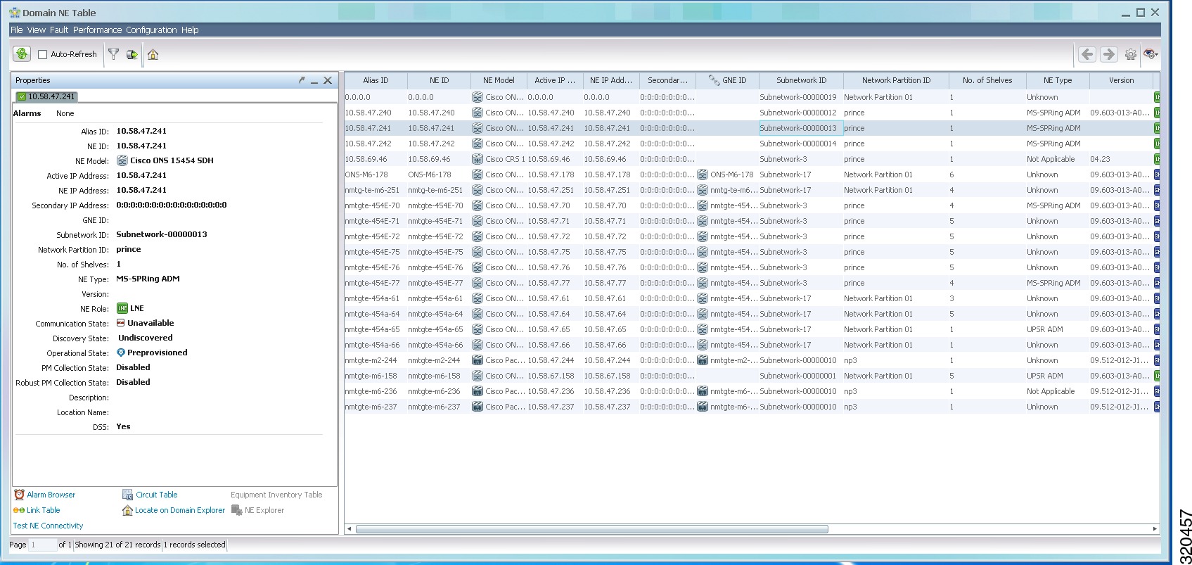
The Domain NE table displays an inventory of all the NEs in the selected Prime Optical domain, group, or subnetwork. Based on your selection criteria, the Domain NE table tells you which NEs are in or out of service, available or unavailable, and so on. The following figure shows an example of the Domain NE table.

Figure 11-1 Domain NE Table


Note See "Icons and Menus Displayed in Prime Optical" for details of all the icons displayed in the window.


You can test NE connectivity, locate an NE on the Domain Explorer, and launch the Alarm Browser from the Domain NE Table. You can also launch the NE Explorer, Equipment Inventory Table, Circuit Report, and Link Table from the Configuration menu in the Domain NE Table.

You can also change the state of an NE by selecting the NE and then choosing Configuration > Change State. The following options are available:

Mark In Service

Mark Out of Service

Mark Under Maintenance


Note All of the above features can also be launched by right-clicking an NE in the Domain NE table and selecting the appropriate option from the popup menu that appears.


11.2.1  Viewing the Domain NE Table

Select a node in the Domain Explorer or Subnetwork Explorer tree and choose File > Domain NE Table. The following table provides descriptions.

Table 11-1 Field Descriptions for the Domain NE Table 

Field
Description

Alias ID

Alias name of the NE.

NE ID

Name of the selected NE.

NE Model

Selected NE model:

Cisco ONS 15216

Cisco ONS 15305

Cisco ONS 15310 CL

Cisco ONS 15310 MA or Cisco ONS 15310 MA SDH

Cisco ONS 15327

Cisco ONS 15454 or Cisco ONS 15454 SDH

Cisco ONS 15530

Cisco ONS 15540

Cisco ONS 15600 or Cisco ONS 15600 SDH

Active IP Address

IP address of the GNE, in IPv4 or IPv6 format.

NE IP Address

IP address of the NE, in IPv4 or IPv6 format. Prime Optical tries to connect to the NE using an IPv4 address. If the IPv4 address is unreachable, Prime Optical tries to connect to the NE using its IPv6 address, if configured and reachable.

Note If the node is a gateway network element (GNE) or a LAN-connected network element (LNE), the NE IP address is the same as the active IP address.

Secondary IP Address

Secondary IP address of the NE. If the IPv6 address is unreachable, Prime Optical tries to connect to the NE using its IPv4 address.

Note If IPv6 is not configured on the NE, the IP address 0:0:0:0:0:0:0:0 is shown.

GNE ID

ID for the GNE on the selected NE's ring.

Subnetwork ID

Name of the subnetwork associated with the selected NE.

Network Partition ID

Name of the network partition to which this NE is associated.

No. of Shelves

Number of shelves supported by the NE.

NE Type

Type of NE.

Version

NE software version that is running.

NE Role

Role of the selected NE.

Communication State

Connectivity state between Prime Optical and the selected NE: Available, Unavailable, and Initialization Failed.

Discovery State

Discovery state of the selected NE: Initializing or Synch Configuration.

Operational State

Current operational state of the system: In Service, Under Maintenance, or Out of Service.

PM Collection State (not applicable to ONS 15216)

Whether performance monitoring collection is enabled or disabled. You can configure the PM collection state in the Domain Explorer > Network Element Properties pane > Status tab.

Robust PM Collection State (not applicable to all NEs)

Whether robust PM collection is enabled or disabled. You can configure the robust PM collection state in the Domain Explorer > Network Element Properties pane > Status tab.

Note You cannot collect robust PM data until at least one 15-minute or one 1-day interval has been collected in normal operation.

Note Robust PM data collection applies only to CTC-based NEs and to the ONS 15305, ONS 15530, and ONS 15540. Robust PM collection is not supported for the ONS 15216.

Note You can collect up to 8 hours of 15-minute robust PM data for CTC-based NEs.

Note You can collect up to the previous day's 1-day robust PM data for CTC-based NEs.

Note For the ONS 15530 and ONS 15540 ESPx, you can collect up to 24 hours (96 previous missed intervals) of 15-minute robust PM data and up to the previous day's 1-day robust PM data.

Note For the ONS 15540 ESP, you can collect up to 24 hours (96 previous missed intervals) of 15-minute robust PM data.

Description

Information that a user might have entered to describe the selected NE.

Location Name

Geographic location of the NE.

DSS

Indicates whether or not the selected CTC-based SONET or CTC-based SDH NE serves as a designated SOCKS server (DSS). If so, the NE manages connectivity among other NEs through firewalls. Values for the DSS column are Yes, No, and Not Applicable.


Tip The Dashboard window displays an NE counter icon. This counter lists the total number of NEs in the domain. Click the counter to open the Domain NE table.


11.2.2  Filtering the Domain NE Table


Step 1 Select a node in the Domain Explorer or Subnetwork Explorer tree.

Step 2 Choose File > Domain NE Table. The Domain NE table opens. (See Figure 11-1.)

Step 3 Choose File > Filter (or click the Filter Data tool). The Filter dialog box opens.

Step 4 Specify the filter criteria to display the results in the Domain NE table. The following table describes the fields in the filter.

Step 5 Click OK. The filtered data is displayed in the Domain NE table.


Table 11-2 Field Descriptions for the Domain NE Table Filter 

Field
Description
NE ID Tab

Available NE ID/Selected NE ID

List of available NE IDs. Click Add and Remove to move NE IDs to and from the Selected NE ID list.

Note Use the scroll bars at the bottom and right side of the Available NE ID list and the Selected NE ID list to display all options in the lists.

Inventory Tab

Communication State

Filters NEs according to their communication state (Available, Unavailable, and Initialization Failed).

Operational State

Filters NEs according to their operational state (In Service, Out of Service, Preprovisioned, or Under Maintenance).

PM Collection State

Filters NEs according to their PM collection state (Enabled; 5,10,15 Min Collection; 1 Day Collection; Disabled).

Robust PM Collection State

Filters NEs according to their robust PM data collection state (Enabled, 15 Min Collection, 1 Day Collection, Disabled).

GNE

Filters domain inventory data based on GNE IDs. You can select <ALL> to filter all GNE IDs or you can choose a particular GNE ID from the drop-down list.

NP ID Tab

Available Network Partitions/Selected Network Partitions

Filters domain inventory data based on network partition. Click Add and Remove to move network partitions to and from the Selected Network Partitions list.

Note Use the scroll bars at the bottom and right side of the Available Network Partitions list and the Selected Network Partitions list to display all options in the lists.


11.2.3  Viewing NE Properties from the Domain NE Table

To view NE properties from the Domain NE Table, do the following:


Step 1 From the Toggle Frames Visibility drop-down list, select Properties. A dockable Properties window displays the following NE properties:

Alias ID

NE ID

NE Model

Active IP Address

NE IP Address

Secondary IP Address

GNE ID

Subnetwork ID

Network Partition ID

No. of Shelves

NE Type

Version

NE Role

Communication State

Discovery State

Operational State

PM Collection State (not applicable to ONS 15216)

Robust PM Collection State (not applicable to all NEs)

Description

Location Name

DSS

The following links are also available at the bottom of the Properties window:

Alarm Browser—Launches the Alarm Browser for the selected NE.

Circuit Report—Launches the Circuit Report for the selected NE.

Equipment Inventory Table—Launches the Equipment Inventory Table for the selected NE.

Link Table—Launches the Link Table for the selected NE.

Locate on Domain Explorer—Locates the selected NE on the Domain Explorer.

NE Explorer—Launches the NE Explorer for the selected NE.

Test NE Connectivity—Tests connectivity to the selected NE using the community string configured in the Prime Optical client.


11.2.4  Viewing the ENE Devices Table

Use the ENE Devices table to view subtending end network elements (ENEs) that are supported by a given GNE. The GNE-ENE relationship is calculated on a theoretical projection, which does not necessarily equate to a real network situation.


Step 1 Select a GNE node in the Domain Explorer or Subnetwork Explorer tree.

Step 2 Choose File > ENE Devices. The ENE Devices table opens.

The fields in the ENE Devices table are identical to the fields in the Domain NE table (see Table 11-1), except that the ENE Devices table shows only those ENEs that are associated with the selected GNE.


11.2.5  Viewing the TNE Devices Table

Use the TNE Devices table to view information about each tunnel NE (TNE) that Prime Optical manages. The Edit menu options allow you to open, close, or modify an individual TL1 tunnel.


Step 1 Select any node in the Domain Explorer or Subnetwork Explorer tree.

Step 2 Choose File > TNE Devices. The TNE Devices (Tunnel) table opens. The following table provides descriptions.

Step 3 (Optional) To open, close, or modify a TL1 tunnel, select an individual TNE in the table and choose any of the following menu options:

Edit > Open Tunnel—Opens a TL1 tunnel on the selected TNE. See Opening a TL1 Tunnel.

Edit > Close Tunnel—Closes the TL1 tunnel on the selected TNE. See Closing a TL1 Tunnel.

Edit > Modify Tunnel—Allows you to modify the settings of the selected TNE. See Modifying a TL1 Tunnel.


Table 11-3 Field Descriptions for the TNE Devices Table 

Field
Description

TNE ID

ID of the selected tunnel NE.

Alias ID

Alias of the selected tunnel NE.

GNE IP Address

IP address of the non-Cisco GNE.

TL1 Port Number

Port number used by the non-Cisco GNE to support the TL1 tunnel.

Encoding Type

Type of encoding used by the selected tunnel NE. Values are LV + Base64 Payload, LV + Binary Payload, or Raw.

Tunnel Status

Status of the selected TL1 tunnel.


11.2.6  Filtering the TNE Devices Table


Step 1 Select any node in the Domain Explorer or Subnetwork Explorer tree.

Step 2 Choose File > TNE Devices. The TNE Devices (Tunnel) table opens.

Step 3 Choose File > Filter (or click the Filter Data tool). The Filter dialog box opens.

Step 4 Specify the filter criteria to display the results in the TNE Devices (Tunnel) table. The following table describes the fields in the filter.

Step 5 Click OK. The filtered data is displayed in the TNE Devices (Tunnel) table.


Table 11-4 Field Descriptions for the TNE Devices Table Filter 

Field
Description
TNE ID Tab

Available Network Partitions/Selected Network Partitions

Filters TL1 tunnel data based on network partition. Click Add and Remove to move network partitions to and from the Selected Network Partitions list.

GNE IP Address Tab

Available Network Partitions/Selected Network Partitions

Filters GNE IP address data based on network partition. Click Add and Remove to move network partitions to and from the Selected Network Partitions list.

Tunnel Status Tab

Connection Type

Filters TL1 tunnel data based on the status of the tunnel connection. Check any of the following check boxes:

Open—Filters on open TL1 tunnels.

Close—Filters on closed TL1 tunnels.

Initial—Filters on TL1 tunnels that are initializing.


11.2.7  Opening a TL1 Tunnel

Use the Open TL1 Tunnel dialog box to open a TL1 tunnel on the selected TNE.


Step 1 Select any node in the Domain Explorer or Subnetwork Explorer tree.

Step 2 Choose File > TNE Devices. The TNE Devices (Tunnel) table opens.

Step 3 In the TNE Devices table, select an individual TNE and choose Edit > Open Tunnel (or click the Open Tunnel tool). The Open TL1 Tunnel dialog box opens. The following table provides descriptions.


Note The Open Tunnel menu option and tool are dimmed if the TNE Devices table is empty.


Step 4 After making your selections, click Finish. The Job Monitor table (Administration > Job Monitor) reports the result of the operation.


Table 11-5 Field Descriptions for the Open TL1 Tunnel Dialog Box 

Field
Description

TNE ID

Display only. ID of the selected tunnel NE.

Alias ID

Display only. Alias of the selected tunnel NE.

GNE IP Address

Display only. IP address of the non-Cisco GNE.

Port

Display only. Port number used by the non-Cisco GNE to support the TL1 tunnel.

TL1 Encoding

Display only. Type of encoding used by the selected tunnel NE. Values are LV + Base64 Payload, LV + Binary Payload, or Raw.

Job Comments

Enter comments about the TL1 tunnel, if needed.

Time (time zone)

Set a time to open the TL1 tunnel. Click Now to open the tunnel immediately, or click At Time and specify when to open the tunnel, in 5-minute increments.

Note The time zone can be GMT, a user-defined offset from GMT, or local time, depending on what is specified in the User Preferences dialog box.


11.2.8  Closing a TL1 Tunnel

Use the Close TL1 Tunnel dialog box to close the TL1 tunnel on the selected TNE.


Step 1 Select any node in the Domain Explorer or Subnetwork Explorer tree.

Step 2 Choose File > TNE Devices. The TNE Devices (Tunnel) table opens.

Step 3 In the TNE Devices table, select an individual TNE and choose Edit > Close Tunnel (or click the Close Tunnel tool). The Close TL1 Tunnel dialog box opens. The following table provides descriptions.

Step 4 After making your selections, click Finish. A warning message is displayed, alerting you that closing a tunnel will result in loss of connectivity to the selected TNE and all of its ENEs.

The Job Monitor table (Administration > Job Monitor) reports the result of the operation.


Table 11-6 Field Descriptions for the Close TL1 Tunnel Dialog Box 

Field
Description

TNE ID

Display only. ID of the selected tunnel NE.

Alias ID

Display only. Alias of the selected tunnel NE.

GNE IP Address

Display only. IP address of the non-Cisco GNE.

Port

Display only. Port number used by the non-Cisco GNE to support the TL1 tunnel.

TL1 Encoding

Display only. Type of encoding used by the selected tunnel NE. Values are LV + Base64 Payload, LV + Binary Payload, or Raw.

Job Comments

Enter comments about the TL1 tunnel closure, if needed.

Time (time zone)

Set a time for the TL1 tunnel closure. Click Now to close the tunnel immediately, or click At Time and specify when to close the tunnel, in 5-minute increments.

Note The time zone can be GMT, a user-defined offset from GMT, or local time, depending on what is specified in the User Preferences dialog box.


11.2.9  Modifying a TL1 Tunnel

Use the Modify TL1 Tunnel dialog box to modify the settings of an individual TNE.


Step 1 Select any node in the Domain Explorer or Subnetwork Explorer tree.

Step 2 Choose File > TNE Devices. The TNE Devices (Tunnel) table opens.

Step 3 In the TNE Devices table, select an individual TNE and choose Edit > Modify Tunnel (or click the Modify Tunnel tool). The Modify TL1 Tunnel dialog box opens. The following table provides descriptions.

Step 4 After modifying the selections, click Finish. The Job Monitor table (Administration > Job Monitor) reports the result of the operation.


Table 11-7 Field Descriptions for the Modify TL1 Tunnel Dialog Box 

Field
Description

TNE ID

Display only. ID of the selected tunnel NE.

Alias ID

Display only. Alias of the selected tunnel NE.

GNE IP Address

Modify the IP address of the non-Cisco GNE.

Port

Modify the port number used by the non-Cisco GNE to support the TL1 tunnel.

TL1 Encoding

Modify the type of encoding used by the selected tunnel NE. Values are LV + Base64 Payload, LV + Binary Payload, or Raw.

Job Comments

Enter comments about the TL1 tunnel modification, if needed.

Time (time zone)

Set a time for the tunnel modification. Click Now to begin modification immediately, or click At Time and specify when to begin modification, in 5-minute increments.

Note The time zone can be GMT, a user-defined offset from GMT, or local time, depending on what is specified in the User Preferences dialog box.


11.3  Equipment Inventory Table

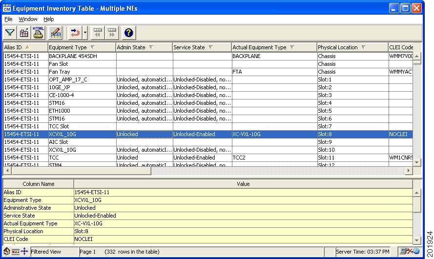
The Equipment Inventory table displays a complete inventory of the components of the selected NE or of the NEs in a group or subnetwork. The following figure shows an example of the Equipment Inventory table.

Figure 11-2 Equipment Inventory Table


Note See "Icons and Menus Displayed in Prime Optical" for details of all the icons displayed in the window.


11.3.1  Viewing an Equipment Inventory Table


Step 1 In the Domain Explorer or Subnetwork Explorer tree, select the NE, group, or subnetwork for which you want to view inventory data, and choose Configuration.

Step 2 From the Configuration menu, select the NE model and choose Equipment Inventory Table. The Equipment Inventory table for the selected NE model opens.


The following sections provide information about the individual Equipment Inventory tables:

ONS 15216 Equipment Inventory Table

ONS 15305 Equipment Inventory Table

Equipment Inventory Table for CTC-Based NEs

ONS 155xx Equipment Inventory Table


Note The Equipment Inventory table is not available for unmanaged NEs.


11.3.1.1  ONS 15216 Equipment Inventory Table

The ONS 15216 Equipment Inventory table displays a complete list of the ONS 15216 system inventory. The following table provides descriptions.

Table 11-8 Field Descriptions for the ONS 15216 Equipment Inventory Table 

Field
Description

Alias ID

Alias name of the NE.

Equipment Type

NE model type.

Physical Location

Location where the NE is installed.

Wavelength(s)

Number of wavelengths for this NE.

CLEI Code

CLEI code for the device. CLEI code is an industry-standard code that precisely defines a component.

Product Name

Name of the product.

Serial Number

Serial number of the device.

NE ID

Name of the selected NE.


11.3.1.2  ONS 15305 Equipment Inventory Table

The ONS 15305 Equipment Inventory table displays a complete list of the ONS 15305 system inventory. The following table provides descriptions.

Table 11-9 Field Descriptions for the ONS 15305 Equipment Inventory Table 

Field
Description

Alias NE ID

Alias name of the NE.

Module Name

Generic type of card.

Physical Location

Slot number where the card appears.

Install State

Installation state of the card.

Expected Module

Default card for the slot.

Operational State

Operational state of the card. (Not applicable if the slot is empty.)

Software Version

Version of software present on the card. (Not applicable if the slot is empty.)

Board Serial Number

Serial number of the card.

Hardware Version

Hardware version of the card. (Not applicable if the slot is empty.)

NE ID

Name of the selected NE.


11.3.1.3  Equipment Inventory Table for CTC-Based NEs

The Equipment Inventory table for CTC-based NEs displays a complete list of the ONS 15305 R3.0, ONS 15310 CL, ONS 15310 MA SONET, ONS 15310 MA SDH, ONS 15327, ONS 15454 SONET, ONS 15454 SDH, ONS 15454-M6, ONS 15454-M2, ONS 15600 SONET, ONS 15600 SDH, CPT 600, or CPT 200 system inventory. This section contains the following tables:

Field Descriptions for the Equipment Inventory Table—CTC-Based NEs

Service State and Fault Secondary State Values

Available Equipment Inventory Fields for Passive Cards

The following table lists common field descriptions for the Equipment Inventory table.

Table 11-10 Field Descriptions for the Equipment Inventory Table—CTC-Based NEs 

Field
Description

Alias ID

Alias name of the NE.

Equipment Type

Generic type of card.

Admin State

User-assigned designation that drives whether an entity is in service or out of service. The administrative state is the driver for the service state. For SONET nodes, values are:

IS—In Service. Able to carry traffic.

OOS, DSBLD—Out of Service. Unable to carry traffic.

IS, AINS—Auto In Service. Alarm reporting is suppressed, but traffic is carried.

OOS, MT—Out of Service, Maintenance. Alarm reporting is suppressed, but traffic is carried and loopbacks are allowed.

OOS, OOG—Out of Service, Out of Group. This state is used to place a member circuit out of the group and to stop sending traffic. OOS, OOG applies only to the cross-connects on the end node where the VCAT resides. For intermediate nodes, the cross-connects are OOS, MT.

For SDH nodes, corresponding values are:

Unlocked (corresponds to IS)

Locked (corresponds to OOS)

Failed (corresponds to FLT)

Locked Maintenance (corresponds to OOS, MT)

Unlocked Automatic In Service (corresponds to IS, AINS)

Note If the NE release does not support the administrative state, this field shows N/A.

Service State

Overall availability of the entity. Values are:

IS-NR—In Service-Normal.

OOS-AU—Out of Service-Autonomous.

OOS-MA—Out of Service-Management.

OOS-AUMA—Out of Service-Autonomous and Management.

In addition, a secondary state provides additional information about the status of the entity. Values for secondary state are:

AINS—Automatic In Service.

DSBLD—Traffic is disabled on the entity.

FLT—Fault secondary state. When an entity is faulted, an FLT state is raised. Equipment and ports in FLT state should be cleared as they transition. Transition states are listed in Table 11-11.

LPBK—Port or connection has a loopback on it.

MEA—Mismatch of equipment due to invalid equipment insertion.

MT—Maintenance, as per the administrative state change.

SWDL—Software download in progress.

UAS—Unassigned. The entity does not exist, has not been created, or has been deleted.

UEQ—Unequipped. There is nothing in the slot.

See Table 11-11 for the Service state-Secondary state possible values.

Note If the NE release does not support the service state, this field shows N/A.

Actual Equipment Type

Specific type of card. This field also shows small form-factor pluggable (SFP) information (such as wavelength, reach, and payload rate), Channel Express (CXP), C Form-Factor Pluggable (CFP), and 10-Gigabit Small Form-Factor Pluggable (XFP) for all line cards and pluggable I/O modules (PIMs) that support pluggable port modules (PPMs).

Note For the Customer Access Panel2 (CAP2) module on the ONS 15600, Prime Optical displays "CAP" for the Equipment Type and "15600-CAP2" for the Actual Equipment Type.

Physical Location

Slot number where the card appears.

Unit number of passive units.

FOG number of the PTSA_GE panels.

For PPMs, this field contains the slot number and the PPM numbers.

CLEI Code

CLEI code for the card. CLEI code is an industry-standard code that precisely defines a component.

Hardware Part Number

Part number used for the card.

Serial Number

Serial number of the card.

Note

Any user-entered comments relating to the equipment.

Hardware Revision

Hardware revision number of the card.

Firmware Version

Firmware version of the card.

Inventory Code

Inventory code of the card.

Application Filename

Name of the file that the card loads from the TCC or XTC flash in order to run its application.

Other Information

Additional information entered by the manufacturer.

Equipment State

Current state of the card. Values are:

Active

Deleted

Empty

Failed

Loading

Mismatch

Not Present

Standby

Product ID

Product ID string of 63 characters maximum. If the card does not support the product ID, the field shows N/A.

Version ID

Version ID string in the format V99_. The version ID always begins with a V and ends with a space. If the card does not support the version ID, the field shows N/A.

NE ID

Name of the selected NE.


The following table lists the service state and fault secondary state values.

Table 11-11 Service State and Fault Secondary State Values 

Service State-Secondary State Possible Values
Initial State Transition
Final State Transition
Equipment

IS-NR

FLT

OOS-AU, FLT

OOS-AU, FLT

All AE Cleared

IS-NR

OOS-AU, FLT

ED: OOS, MT RMV

OOS-AUMA, FLT & MT

OOS-MA, MT

FLT

OOS-AUMA, FLT & MT

OOS-AUMA

FLT

OOS-AUMA, FLT

OOS-AUMA, FLT & MT

All AE Cleared

OOS-MA

Port

IS-NR

FLT

OOS-AU, FLT

OOS-AU. FLT

FLT Cleared

IS-NR

OOS-AU, AINS

FLT

OOS-AU, AINS & FLT

OOS-AU, AINS & FLT

FLT Cleared

OOS-AU, AINS

OOS-MA, MT

FLT

OOS-AUMA & FLT & MT

OOAS-AUMA & FLT & MT

FLT Cleared

OOS-MA & MT

OOS-AUMA & LPBK & MT

FLT

OOS-MA & LPBK & MT & FLT

OOS-AUMA & LPBK & MT & FLT

FLT Cleared

OOS-MA & LPBK & MT & FLT


Passive units are optical devices that the controller card cannot manage and that are not configurable using software. Passive units can be provisioned only in CTC. The following table lists the field descriptions for passive cards.

Table 11-12 Available Equipment Inventory Fields for Passive Cards 

Passive Card Type
Fields

USB-connected

Equipment Type

Administrative State

Service State

Actual Equipment Type

Physical Location

Equipment State

CLEI Code

HW Part Number

Serial Number

HW Revision

Not USB-connected

Equipment Type

Administrative State

Service State

Actual Equipment Type

Physical Location

Equipment State


11.3.1.3.1  Adding a Note to the Equipment Inventory Table

The User Note dialog box allows you to view and add user notes to CTC-based equipment that has a valid serial number in the Equipment Inventory table. If a piece of equipment has a note, a User Note tool appears under the Note column. Comments are visible to all users. You can open the User Note dialog box only if you have read/write permissions. These permissions are configurable in the User Profile wizard > NE Configuration Management category > Equipment Inventory row.


Note You can add user notes only for CTC-based NEs.


Step 1 In the Domain Explorer window, choose Configuration > CTC-Based SONET NEs > Equipment Inventory Table.

The Equipment Inventory table opens.

Step 2 Select a piece of equipment and choose Edit > User Note. The following table describes the fields in the User Note dialog box.


Table 11-13 Field Descriptions for the User Note Dialog Box 

Field
Description

Note

Provides space for you to type your comments about the selected equipment. The maximum length of this field is 2048 characters. To add comments to the previous comments, click the Append radio button. To overwrite the previous comments, click Replace. To delete the comments, click Delete.

Note You cannot enable and disable the Replace and Delete functions in the Control Panel.

History

Displays comments entered by previous users.


11.3.1.4  ONS 155xx Equipment Inventory Table

The ONS 155xx Equipment Inventory table displays a complete list of the system inventory of the selected ONS 15530 or ONS 15540 NE. The following table provides descriptions.

Table 11-14 Field Descriptions for the ONS 155xx Equipment Inventory Table 

Field
Description

Alias ID

Alias name of the NE.

Equipment Type

General type of the component.

Name

Name of the ONS 155xx component.

Module Name

Name of the ONS 155xx module.

Physical Location

Physical location for the component in the NE as a slot, subslot, and port number.

CLEI Code

CLEI code, an industry-standard code that precisely defines a component.

Serial Number

Serial number of the NE.

Hardware Version

Hardware revision of the NE.

Firmware Version

Firmware revision of the NE.

Software Version

Software revision of the NE.

Manufacturer Name

Name of the manufacturer of the NE.

Product Name

Vendor-specific model name; for example, the part number.

Alias

Alias specified for the component by the network manager.

Asset ID

Asset tracking identifier specified for the component by the network manager.

Description

Description of the component.

NE ID

Name of the selected ONS 155xx NE.


11.3.2  Exporting Equipment Inventory Table Data

You can schedule the export of Equipment Inventory table data to a flat file.

The Export Equipment Inventory Table dialog box allows you to export the data as comma-separated values (CSVs) or tab-separated values (TSVs), which are formats commonly used to import data into spreadsheet and database applications for further analysis and manipulation. You can also select a user-specified character as a separator.


Tip If you export data to Microsoft Excel, save the exported file with ".csv" as the filename extension.


To open the Export dialog box, open the Equipment Inventory table for the NE(s); then, click the Export Data to File tool (or choose File > Export). The following table provides descriptions. After making your selections, click OK to export the data.

Table 11-15 Field Descriptions for the Export Equipment Inventory Table Dialog Box 

Field
Description
Field Separator

Comma separated

If selected, the data is exported as comma-separated values.

Tab separated

If selected, the data is exported as tab-separated values.

Other

If selected, the data is exported with the separator that you specify in the Other text field.

Note If you specify a character as a separator and your data contains the same character, the character in the data is automatically enclosed in double quotes. This allows the spreadsheet or database application to understand that the character is part of your data. Regardless of whether you select Comma separated, Tab separated, or Other, Prime Optical automatically encloses text in double quotes if it has a separator.

Export

Selected row(s)

If selected, only the selected rows in the current page are exported.

All rows in current page

If selected, all rows in the current page are exported.

Export Data

Local (file)

If selected, data is exported to a local file on your system. Specify the path directory and the filename. With the Local option, you can export selected rows or all rows in the Equipment Inventory table. By default, exported data is stored in the C:\Cisco\TransportManagerClientversion\exports file.

Server (dir)

If selected, data is exported to a directory on the server. The directory path is a fixed, display-only string. With the Server option, you can export all rows in the Equipment Inventory table; you cannot export selected rows. By default, exported data is stored in the /opt/CiscoTransportManagerServer/export directory.

Time

Time (time zone)

Set a time for the export. Click Now to begin exporting immediately, or click At Time and specify when to begin exporting, in 5-minute increments.

For local exports, you can only select Now. For server exports, you can select Now or At Time.

Note The time zone can be GMT, a user-defined offset from GMT, or local time, depending on what is specified in the User Preferences dialog box.

Repeat

Once

If selected, the export of inventory data to the server occurs once.

Daily

If selected, the export of inventory data to the server occurs daily.

Weekly

If selected, the export of inventory data to the server occurs weekly.

Monthly

If selected, the export of inventory data to the server occurs monthly.

Job Comments

Job Comments

Enter comments about the export. The comments will be attached to the scheduled job.


11.3.3  Filtering the Equipment Inventory Table


Step 1 Select a node in the Domain Explorer or Subnetwork Explorer tree.

Step 2 Choose Configuration > CTC-Based SONET NEs > Equipment Inventory Table. The Equipment Inventory table opens. (See Figure 11-2.)

Step 3 Choose File > Filter (or click the Filter Data tool). The Filter dialog box opens.

Step 4 Specify the filter criteria to display the results in the table. The following table describes the fields in the filter.

Step 5 Click OK. The filtered data is displayed in the Equipment Inventory table.


Table 11-16 Field Descriptions for the Equipment Inventory Table Filter 

Field
Description
NE ID Tab

Available NE ID/Selected NE ID

List of available NE IDs. Click Add and Remove to move NE IDs to and from the Selected NE ID list.

Note Use the scroll bars at the bottom and right side of the Available NE ID list and the Selected NE ID list to display all options in the lists.

Other Tab

Disregard All Other Filter Criteria

Check this check box to ignore all other filter criteria.

Exclude out of service NEs

Check this check box to exclude any NEs that are marked Out of Service.

Actual Equipment Type

NE model type.

HW Part Number

Part number used for the card.

Hardware Version

Hardware version of the card. (Not applicable if the slot is empty.)

Firmware Version

Firmware version of the card.

CLEI Code

CLEI code for the device. CLEI code is an industry-standard code that precisely defines a component.