Feedback
Table Of Contents
Configuring Asynchronous SLIP and PPP
Asynchronous SLIP and PPP Overview
Asynchronous Network Connections and Routing
Asynchronous Interfaces and Broadcasts
How to Configure Asynchronous SLIP and PPP
Configuring Network-Layer Protocols over PPP and SLIP
Configuring Asynchronous Host Mobility
Making Additional Remote Node Connections
Configuring Remote Access to NetBEUI Services
Configuring Performance Parameters
Compressing TCP Packet Headers
Setting the TCP Connection Attempt Time
Compressing IPX Packet Headers over PPP
Controlling Route Cache Invalidation
Customizing SLIP and PPP Banner Messages
Configuration Examples for Asynchronous SLIP and PPP
Basic PPP Configurations Examples
Remote Network Access Using PPP Basic Configuration Example
Remote Network Access Using PPP and Routing IP Example
Remote Network Access Using a Leased Line with Dial-Backup and PPP Example
Multilink PPP Using Multiple Asynchronous Interfaces Example
Configuring Asynchronous SLIP and PPP
This chapter describes how to configure asynchronous Serial Line Internet Protocol (SLIP) and PPP. It includes the following main sections:
•
Asynchronous SLIP and PPP Overview
•
•
To identify the hardware platform or software image information associated with a feature, use the Feature Navigator on Cisco.com to search for information about the feature or refer to the software release notes for a specific release. For more information, see the "Identifying Supported Platforms" section in the "Using Cisco IOS Software" chapter.
For a complete description of the commands in this chapter, refer to the Cisco IOS Dial Technologies Command Reference. To locate documentation of other commands that appear in this chapter, use the command reference master index or search online.
Asynchronous SLIP and PPP Overview
PPP and SLIP define methods of sending IP packets over standard asynchronous serial lines with minimum line speeds of 1200 baud.
Using SLIP or PPP encapsulation over asynchronous lines is an inexpensive way to connect personal computers (PCs) to a network. PPP and SLIP over asynchronous dialup modems allow a home computer to be connected to a network without the cost of a leased line. Dialup PPP and SLIP links can also be used for remote sites that need only occasional remote node or backup connectivity. Both public-domain and vendor-supported PPP and SLIP implementations are available for a variety of computer applications.
The Cisco IOS software concentrates a large number of SLIP or PPP PC or workstation client hosts onto a network interface that allows the PCs to communicate with any host on the network. The Cisco IOS software can support any combination of SLIP or PPP lines and lines dedicated to normal asynchronous devices such as terminals and modems. Refer to RFC 1055 for more information about SLIP, and RFCs 1331 and 1332 for more information about PPP.
SLIP is an older protocol. PPP is a newer, more robust protocol than SLIP, and it contains functions that can detect or prevent misconfiguration. PPP also provides greater built-in security mechanisms.
Note
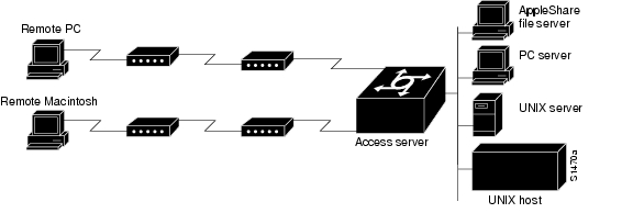
Figure 81 illustrates a typical asynchronous SLIP or PPP remote-node configuration.
Figure 81 Sample SLIP or PPP Remote-Node Configuration
Responding to BOOTP Requests
The BOOTP protocol allows a client machine to discover its own IP address, the address of the router, and the name of a file to be loaded in to memory and executed. There are typically two phases to using BOOTP: first, the client's address is determined and the boot file is selected; then the file is transferred, typically using the TFTP.
PPP and SLIP clients can send BOOTP requests to the Cisco IOS software, and the Cisco IOS software responds with information about the network. For example, the client can send a BOOTP request to learn its IP address and where the boot file is located, and the Cisco IOS software responds with the information.
BOOTP supports the extended BOOTP requests specified in RFC 1084 and works for both PPP and SLIP encapsulation.
BOOTP compares to Reverse Address Resolution Protocol (RARP) as follows: RARP is an older protocol that allows a client to determine its IP address if it knows its hardware address. (Refer to the Cisco IOS IP Configuration Guide for more information about RARP.) However, RARP is a hardware link protocol, so it can be implemented only on hosts that have special kernel or driver modifications that allow access to these raw packets. BOOTP does not require kernel modifications.
Asynchronous Network Connections and Routing
Line configuration commands configure a connection to a terminal or a modem. Interface configuration (async) commands, described in this chapter, configure a line as an asynchronous network interface over which networking functions are performed.
The Cisco IOS software also supports IP routing connections for communication that requires connecting one network to another.
The Cisco IOS software supports protocol translation for PPP and SLIP between other network devices running Telnet, local-area transport (LAT), or X.25. For example, you can send IP packets across a public X.25 packet assembler/disassembler (PAD) network using SLIP or PPP encapsulation when SLIP or PPP protocol translation is enabled. For more information, see the chapter "Configuring Protocol Translation and Virtual Asynchronous Devices" in this publication.
If asynchronous dynamic routing is enabled, you can enable routing at the user level by using the routing keyword with the slip or ppp EXEC command.
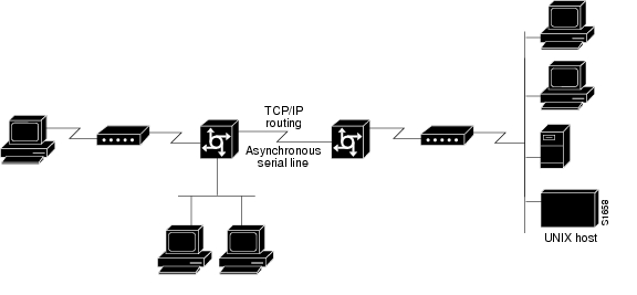
Asynchronous interfaces offer both dedicated and dynamic address assignment, configurable hold queues and IP packet sizes, extended BOOTP requests, and permit and deny conditions for controlling access to lines. Figure 82 shows a sample asynchronous routing configuration.
Figure 82 Sample Asynchronous Routing Configuration
Asynchronous Interfaces and Broadcasts
The Cisco IOS software recognizes a variety of IP broadcast addresses. When a router receives an IP packet from an asynchronous client, it rebroadcasts the packet onto the network without changing the IP header.
The Cisco IOS software receives the SLIP or PPP client broadcasts and responds to BOOTP requests with the current IP address assigned to the asynchronous interface from which the request was received. This facility allows the asynchronous client software to automatically learn its own IP address.
How to Configure Asynchronous SLIP and PPP
To configure SLIP and PPP, perform the tasks in the following sections; all tasks are optional:
•
•
•
•
•
Configuring Network-Layer Protocols over PPP and SLIP
You can configure network-layer protocols, such as AppleTalk, IP, and Internet Protocol Exchange (IPX), over PPP and SLIP. SLIP supports only IP, but PPP supports each of these protocols. See the sections that follow to configure these protocols over PPP and SLIP.
Configuring IP and PPP
To enable IP-PPP (IPCP) on a synchronous or asynchronous interface, use the following commands in interface configuration mode:
Configuring IPX and PPP
You can configure IPX over PPP (IPXCP) on synchronous serial and asynchronous serial interfaces using one of two methods.
The first method associates an asynchronous interface with a loopback interface configured to run IPX. It permits you to configure IPX-PPP on asynchronous interfaces only.
The second method permits you to configure IPX-PPP on asynchronous and synchronous serial interfaces. However, it requires that you specify a dedicated IPX network number for each interface, which can require a substantial number of network numbers for a large number of interfaces.
You can also configure IPX to run on virtual terminal lines configured for PPP. See the section "Enabling IPX and PPP over X.25 to an IPX Network on Virtual Terminal Lines" later in this chapter.
Note
IPX and PPP and Associating Asynchronous Interfaces with Loopback Interfaces
To permit IPX client connections to an asynchronous interface, the interface must be associated with a loopback interface configured to run IPX. To permit such connections, use the following commands beginning in global configuration mode:
Step 1
Router(config)# ipx routing [node]
Enables IPX routing.
Step 2
Router(config)# interface loopback number
Creates a loopback interface, which is a virtual interface existing only inside the router, and begins interface configuration mode.
Step 3
Router(config-if)# ipx network network1
Enables IPX routing on the loopback interface.
Step 4
Router(config-if)# exit
Exits to global configuration mode.
Step 5
Router(config)# interface async number
Enters interface configuration mode for the asynchronous interface.
Step 6
Router(config-if)# ip unnumbered type number
Configures IP unnumbered routing on the interface.
Step 7
Router(config-if)# encapsulation ppp
Enables PPP encapsulation on the interface.
Step 8
Router(config-if)# async mode interactive
Enables interactive mode on an asynchronous interface.
Step 9
Router(config-if)# ipx ppp-client loopback number
Assigns the asynchronous interface to the loopback interface configured for IPX.
Step 10
Router(config-if)# ipx update interval
Turns off Service Advertising Protocol (SAP) updates to optimize bandwidth on asynchronous interfaces.
1 Every interface must have a unique IPX network number.
IPX and PPP Using Dedicated IPX Network Numbers for Each Interface
To enable IPX and PPP, use the following commands beginning in global configuration mode. The first five steps are required. The last step is optional.
Step 1
Router(config)# ipx routing [node]
Enables IPX routing.
Step 2
Router(config)# interface loopback number
Creates a loopback interface, which is a virtual interface existing only inside the router, and begins interface configuration mode.
Step 3
Router(config-if)# encapsulation ppp
Enables PPP encapsulation on the interface.
Step 4
Router(config-if)# async mode interactive
Enables interactive mode on an asynchronous interface.
Step 5
Router(config-if)# ipx network network1
Enables IPX routing on the interface.
Step 6
Router(config-if)# ipx update interval
(Optional) Turns off SAP updates to optimize bandwidth on asynchronous interfaces.
1 Every interface must have a unique IPX network number.
Enabling IPX and PPP over X.25 to an IPX Network on Virtual Terminal Lines
You can enable IPX-PPP on virtual terminal lines, which permits clients to log in to a virtual terminal on a router, invoke a PPP session at the EXEC prompt to a host, and run IPX to the host.
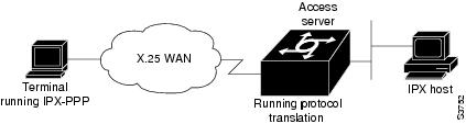
For example, in Figure 83, the client terminal on the X.25 network logs in to the access server via a virtual terminal line, which is configured for IPX-PPP. When the user connects to the access server and the EXEC prompt appears, enter the PPP command to connect to the IPX host. The virtual terminal is configured to run IPX, so when the PPP session is established from the access server, the terminal can access the IPX host using an IPX application.
Figure 83 IPX-PPP on a Virtual Asynchronous Interface
To enable IPX to run over your PPP sessions on virtual terminal lines, use the following commands beginning in global configuration mode:
Step 1
Router(config)# ipx routing [node]
Enables IPX routing.
Step 2
Router(config)# interface loopback number
Creates a loopback interface and begins interface configuration mode.
Step 3
Router(config-if)# ipx network network1
Enables a virtual IPX network on the loopback interface.
Step 4
Router(config-if)# vty-async ipx ppp-client loopback number
Enables IPX-PPP on virtual terminal lines by assigning it to the loopback interface configured for IPX.
1 Every loopback interface must have a unique IPX network number.
Configuring AppleTalk and PPP
You can configure an asynchronous interface so that users can access AppleTalk zones by dialing in to the router via PPP through this interface. Users accessing the network can run AppleTalk and IP natively on a remote Macintosh, access any available AppleTalk zones from Chooser, use networked peripherals, and share files with other Macintosh users. This feature is referred to as AppleTalk Control Protocol (ATCP).
You create a virtual network that exists only for accessing an AppleTalk internet through the server. To create a new AppleTalk zone, enter the appletalk virtual-net command and use a new zone name; this network number is then the only one associated with this zone. To add network numbers to an existing AppleTalk zone, use this existing zone name in the command; this network number is then added to the existing zone. Routing is not supported on these interfaces.
To enable ATCP for PPP, use the following commands in interface configuration (asynchronous) mode:
Configuring IP and SLIP
To enable IP-SLIP on a synchronous or asynchronous interface, use the following commands in interface configuration mode:
Configuring Asynchronous Host Mobility
The access server supports a packet tunneling strategy that extends the internetwork—in effect creating a virtual private link for the mobile user. When a user activates asynchronous host mobility, the access server on which the remote user dials in becomes a remote point of presence (POP) for the home network of the user. Once logged in, users experience a server environment identical to the one that they experience when they connect directly to the "home" access server.
Once the network-layer connection is made, data packets are tunneled at the physical or data link layer instead of at the protocol layer. In this way, raw data bytes from dial-in users are transported directly to the "home" access server, which processes the protocols.
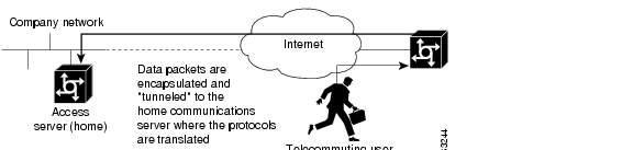
Figure 84 illustrates the implementation of asynchronous host mobility on an extended internetwork. A mobile user connects to an access server on the internetwork and, by activating asynchronous host mobility, is connected to a "home" access server configured with the appropriate username. The user sees an authentication dialog or prompt from the "home" system and can proceed as if he or she were connected directly to that device.
Figure 84 Asynchronous Host Mobility
Asynchronous host mobility is enabled with the tunnel EXEC command and the ip tcp async-mobility server global configuration command. The ip tcp async-mobility server command establishes asynchronous listening on TCP tunnel port 57. The tunnel command sets up a network-layer connection to the specified destination. Both commands must be used. The access server accepts the connection, attaches it to a virtual terminal line, and runs a command parser capable of running the normal dial-in services. After the connection is established, data is transferred between the modem and network connection with a minimum of interpretations. When communications are complete, the network connection can be closed and terminated from either end.
To enable asynchronous host mobility, use the following commands beginning in global configuration mode:
To connect from a router other than a Cisco router, you must use Telnet. After a connection is established, you receive an authentication dialog or prompt from your home router, and can proceed as if you are connected directly to that router. When communications are complete, the network connection can be closed and terminated from either end of the connection.
Making Additional Remote Node Connections
This section describes how to connect devices across telephone lines by using PPP and SLIP. It includes the following sections:
Creating PPP Connections
When you connect from a remote node computer through an asynchronous port on an access server to the EXEC facility to connect from the access server to a device on the network, use the following command in EXEC mode:
Router> ppp {/default | {remote-ip-address | remote-name} [@tacacs-server]} [/routing]
Creates a PPP connection.
If you specify an address for the TACACS server using /default or tacacs-server, the address must be the first parameter in the command after you type ppp. If you do not specify an address or enter /default, you are prompted for an IP address or host name. You can enter /default at this point.
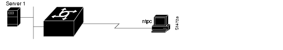
For example, if you are working at home on the device named ntpc in Figure 85 and want to connect to Server 1 using PPP, you could dial in to the access server. When you connect to the EXEC prompt on the access server, enter the ppp command to connect with the device.
Figure 85 Using the ppp Command
To terminate a session, disconnect from the device on the network using the command specific to that device. Then, exit from EXEC mode by using the exit command.
Making SLIP Connections
To make a serial connection to a remote host by using SLIP, use the following command in EXEC mode:
Router> slip [/default] {remote-ip-address | remote-name} [@tacacs-server] [/routing]} [/compressed]
Creates a SLIP connection.
Your system administrator can configure SLIP to expect a specific address or to provide one for you. It is also possible to set up SLIP in a mode that compresses packets for more efficient use of bandwidth on the line.
If you specify an address for the TACACS server using /default or tacacs-server, the address must be the first parameter in the command after you type slip. If you do not specify an address or enter /default, you are prompted for an IP address or host name. You can enter /default at this point.
If you do not use the tacacs-server argument to specify a TACACS server for SLIP address authentication, the TACACS server specified at login (if any) is used for the SLIP address query.
To optimize bandwidth on a line, SLIP enables compression of the SLIP packets using Van Jacobson TCP header compression as defined in RFC 1144.
To terminate a session, disconnect from the device on the network using the command specific to that device. Then, exit from EXEC mode by using the exit command.
Configuring Remote Access to NetBEUI Services
NetBIOS Extended User Interface (NetBEUI) is a simple networking protocol developed by IBM for use by PCs in a LAN environment. It is an extension of the original Network Basic Input/Output System (NetBIOS) from IBM. NetBEUI uses a broadcast-based name to 802.x address translation mechanism. Because NetBEUI has no network layer, it is a nonroutable protocol.
The NetBIOS Frames Control Protocol (NBFCP) enables packets from a NetBEUI application to be transferred via a PPP connection. NetBEUI/PPP is supported in the access server and Cisco enterprise images only.
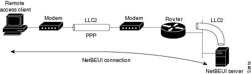
Using the Cisco IOS implementation, remote NetBEUI users can have access to LAN-based NetBEUI services. The PPP link becomes the ramp for the remote node to access NetBIOS services on the LAN. (See Figure 86.) An Logical Link Control, type 2 (LLC2) connection is set up between the remote access client and router, and a second LLC2 connection is set up between the router and the remote access (NetBEUI) server.
Figure 86 NetBEUI Connection
By supporting NetBEUI remote clients over PPP, Cisco routers function as a native NetBEUI dial-in router for remote NetBEUI clients. Thus, you can offer remote access to a NetBEUI network through asynchronous or ISDN connections.
To enable a remote access client using a NetBEUI application to connect with the remote router providing NetBEUI services, configure interfaces on the remote access client side and the remote router side by using the following command in interface configuration mode:
To view NetBEUI connection information, use the following command in EXEC mode:
Configuring Performance Parameters
To tune IP performance, complete the tasks in the following sections:
•
•
•
•
•
•
Compressing TCP Packet Headers
You can compress the headers of your TCP/IP packets to reduce their size and thereby increase performance. Header compression is particularly useful on networks with a large percentage of small packets, such as those supporting many Telnet connections. This feature compresses only the TCP header, so it has no effect on UDP packets or other protocol headers. The TCP header compression technique, described fully in RFC 1144, is supported on serial lines using High-Level Data Link Control (HDLC) or PPP encapsulation. You must enable compression on both ends of a serial connection.
You can optionally specify outgoing packets to be compressed only when TCP incoming packets on the same interface are compressed. If you do not specify this option, the Cisco IOS software will compress all traffic. The default is no compression.
You can also specify the total number of header compression connections that can exist on an interface. You should configure one connection for each TCP connection through the specified interface.
To enable compression, use the following commands in interface configuration mode:
Note
Setting the TCP Connection Attempt Time
You can set the amount of time that the Cisco IOS software will wait to attempt to establish a TCP connection. In previous versions of the Cisco IOS software, the system would wait a fixed 30 seconds when attempting to make the connection. This amount of time is not enough in networks that have dialup asynchronous connections, such as a network consisting of dial-on-demand links that are implemented over modems, because it will affect your ability to use Telnet over the link (from the router) if the link must be brought up.
Because the connection attempt time is a host parameter, it does not pertain to traffic going through the router, just to traffic originated at it.
To set the TCP connection attempt time, use the following command in global configuration mode:
Router(config)# ip tcp synwait-time seconds
Sets the amount of time for which the Cisco IOS software will wait to attempt to establish a TCP connection.
Compressing IPX Packet Headers over PPP
The Cisco IOS software permits compression of IPX packet headers over various WAN media. There are two protocols for IPX compression on point-to-point links:
•
•
Cisco routers support IPX Header Compression (CIPX) on all point-to-point Novell interfaces over various WAN media.
CIPX is described in RFC 1553, Compressing IPX Headers Over WAN Media. The CIPX algorithm is based on the same concepts as Van Jacobson TCP/IP header compression algorithm. CIPX operates over PPP WAN links using either the IPXCP or IPXWAN communications protocols.
CIPX compresses all IPX headers and IPX/NCP headers for Novell packets with the following Network Control Program (NCP) packet types:
•
•
In this version of software, CIPX is configurable only for PPP links.
CIPX header compression can reduce header information from 30 bytes down to as little as 1 byte. This reduction can save bandwidth and reduce costs associated with IPX routing over WAN links that are configured to use IPXCP or IPXWAN.
Consider the following issues before implementing CIPX:
•
•
To configure CIPX, use the following command in global configuration mode:
Router(config)# ipx compression cipx number-of-slots
Compresses IPX packet headers in a PPP session.
Note
Enabling Fast Switching
Fast switching involves the use of a high-speed switching cache for IP routing. With fast switching, destination IP addresses are stored in the high-speed cache so that some time-consuming table lookups can be avoided. The Cisco IOS software generally offers better packet transfer performance when fast switching is enabled.
To enable or disable fast switching, use the following commands in interface configuration mode:
Controlling Route Cache Invalidation
The high-speed route cache used by IP fast switching is invalidated when the IP routing table changes. By default, the invalidation of the cache is delayed slightly to avoid excessive CPU load while the routing table is changing.
To control route cache invalidation, use the following commands in global configuration mode as needed for your network:
Note
Customizing SLIP and PPP Banner Messages
This feature enables you to customize the banner that is displayed when making a SLIP or PPP connection to avoid connectivity problems the default banner message causes in some non-Cisco SLIP and PPP dialup software. This feature is particularly useful when legacy client applications require a specialized connection string.
To configure the SLIP-PPP banner message, use the following command in global configuration mode:
Router(config)# banner slip-ppp d message d
Configures the SLIP-PPP banner to display a customized message.
You can also use tokens in the banner message to display current IOS configuration variables. Tokens are keywords of the form $(token). When you include tokens in a banner command, Cisco IOS will replace $(token) with the corresponding configuration variable.
Table 35 lists the tokens that you can use in the banner slip-ppp command.
Configuration Examples for Asynchronous SLIP and PPP
This section provides the following examples:
•
•
•
•
•
Basic PPP Configurations Examples
The following example illustrates how to make a connection when the system administrator defines a default IP address by including the peer default ip address command in interface configuration mode.
Note
Once a correct password is entered, you are placed in SLIP mode, and the IP address appears:
Router> slipPassword:Entering SLIP mode.Your IP address is 192.168.7.28, MTU is 1524 bytesThe following example shows the prompts displayed and the response required when dynamic addressing is used to assign the SLIP address:
Router> slipIP address or hostname? 192.168.6.15Password:Entering SLIP modeYour IP address is 192.168.6.15, MTU is 1524 bytesIn the previous example, the address 192.168.6.15 had been assigned as the default. Password verification is still required before SLIP mode can be enabled, as follows:
Router> slip defaultPassword:Entering SLIP modeYour IP address is 192.168.6.15, MTU is 1524 bytesThe following example illustrates the implementation of header compression on the interface with the IP address 172.16.2.1:
Router> slip 172.16.2.1 /compressedPassword:Entering SLIP mode.Interface IP address is 172.16.2.1, MTU is 1500 bytes.Header compression will match your system.In the preceding example, the interface is configured for ip tcp header-compression passive, which permitted the user to enter the /compressed keyword at the EXEC mode prompt. The message "Header compression will match your system" indicates that the user has specified compression. If the line was configured for ip tcp header-compression on, this line would read "Header compression is On."
The following example specifies a TACACS server named parlance for address authentication:
Router> slip 10.0.0.1@parlancePassword:Entering SLIP mode.Interface IP address is 10.0.0.1, MTU is 1500 bytesHeader compression will match your system.The following example sets the SLIP-PPP banner using several tokens and the percent sign (%) as the delimiting character:
Router(config)# banner slip-ppp %Enter TEXT message. End with the character '%'.Starting $(encap) connection from $(gate-ip) to $(peer-ip) using a maximum packet size of $(mtu) bytes... %When you enter the slip command, you will see the following banner. Notice that the $(token) syntax is replaced by the corresponding configuration variables.
Starting SLIP connection from 192.168.69.96 to 172.16.80.8 using a maximum packet size of
1500 bytes...
Remote Node NetBEUI Examples
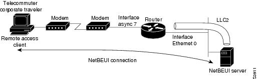
In the following example, asynchronous interface 7 and Ethernet interface 0 are configured to enable NetBEUI connectivity between the corporate telecommuter client and the remote access (NetBEUI) server. The PC client is running the Chat legacy application in Windows NT to connect with the remote server. (See Figure 87.)
Figure 87 Connecting a Remote NetBEUI Client to a Server Through a Router
The configuration for the router is as follows:
interface async 7netbios nbfencapsulation pppYou would also need to configure security, such as TACACS+, RADIUS, or another form of login authentication on the router.
Remote Network Access Using PPP Basic Configuration Example
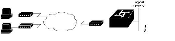
Figure 88 illustrates a simple network configuration that includes remote PCs with modems connected via modem to a router. The cloud is a Public Switched Telephone Network (PSTN). The modems are connected via asynchronous lines, and the access server is connected to a local network.
In this example, the following is configured:
•
•
•
Figure 88 Remote Network Access Using PPP
This default address indicates the address of the remote PC to the server, unless the user explicitly specifies another when starting the PPP session.
The server is configured for interactive mode with autoselect enabled, which allows the user to automatically begin a PPP session upon detection of a PPP packet from the remote PC; or, the remote PC can explicitly begin a PPP session by entering the ppp EXEC command at the prompt.
The configuration is as follows:
ip routing!interface ethernet 0ip address 192.168.32.12 255.255.255.0!interface async 1encapsulation pppasync mode interactiveasync default ip address 192.168.32.51async dynamic addressip unnumbered ethernet 0line 1autoselect pppmodem callinspeed 19200Remote Network Access Using PPP and Routing IP Example
Figure 89 illustrates a network configuration that provides routing functionality, allowing routing updates to be passed across the asynchronous lines.
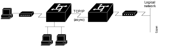
This network is composed of remote and local PCs connected via modem and network connections to an access server. This access server is connected to a second access server via an asynchronous line running TCP/IP. The second access server is connected to a local network via modem.
For this scenario, you will need to configure the following:
•
•
•
•
Figure 89 Routing on an Asynchronous Line Using PPP
The configuration is as follows:
interface async 1encapsulation pppasync mode interactiveasync default ip address 192.168.32.10async dynamic addressip unnumbered ethernet 0async dynamic routingIf you want to pass IP routing updates across the asynchronous link, enter the following commands:
line 1autoselect pppmodem callinspeed 19200Next, enter the following commands to configure the asynchronous lines between the access servers beginning in global configuration mode:
interface async 2async default ip address 192.168.32.55ip tcp header compression passiveFinally, configure routing as described in the Cisco IOS IP Configuration Guide using one of the following methods. The server can route packets three different ways.
•
•
•
Remote Network Access Using a Leased Line with Dial-Backup and PPP Example
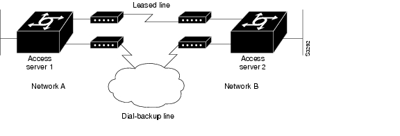
Figure 90 illustrates a scenario where two networks are connected via access servers on a leased line. Redundancy is provided by a dial-backup line over the PSTN so that if the primary leased line goes down, the dial-backup line will be automatically brought up to restore the connection. This configuration would be useful for using an auxiliary port as the backup port for a synchronous port.
For this scenario, you would need to configure the following:
•
•
•
•
•
Figure 90 Asynchronous Leased Line with Backup
The configuration for this scenario follows:
hostname routerA!username routerB password ciscochat-script backup "" "AT" TIMEOUT 30 OK atdt\T TIMEOUT 30 CONNECT \c !!interface Serial0backup interface Async1ip address 192.168.222.12 255.255.255.0!interface Async1ip address 172.16.199.1 255.255.255.0encapsulation pppasync default ip address 172.16.199.2async dynamic addressasync dynamic routingasync mode dedicateddialer in-banddialer map IP 172.16.199.2 name routerB modem-script backup broadcast 3241129 dialer-group 1ppp authentication chap!dialer-list 1 protocol ip permit!line aux 0modem InOutrxspeed 38400txspeed 38400Multilink PPP Using Multiple Asynchronous Interfaces Example
The following example shows how to configure MLP using multiple asynchronous interfaces:
chat-script backup "" "AT" TIMEOUT 30 OK atdt\T TIMEOUT 30 CONNECT \c!ip address-pool localip pool foo 10.0.1.5 10.0.1.15!int as 1 (2, 3)no ip addressdialer in-bandencapsulation pppppp multilinkdialer-rotary 1!interface dialer 1encaps pppip unnumbered ethernet 0peer default ip addr pool fooppp authentication chapppp multilinkdialer in-banddialer map ip 10.200.100.9 name WAN-R3 modem-script backup broadcast 2322036dialer load-threshold 5 eitherdialer-group 1!dialer-list 1 protocol ip permit!line line 1 3modem InOutspeed 115000